-
Paper Information
- Paper Submission
-
Journal Information
- About This Journal
- Editorial Board
- Current Issue
- Archive
- Author Guidelines
- Contact Us
Journal of Safety Engineering
p-ISSN: 2325-0003 e-ISSN: 2325-0011
2013; 2(2): 39-44
doi:10.5923/j.safety.20130202.04
Investigation of Test Instruments for EM Shielding Effectiveness of Conductive Fabrics and Their Composites
 Abstract
 Reference
 Full-Text PDF
 Full-text HTML
Devrim D. Soyaslan
Department of Textile Eng., Engineering and Architecture Faculty, University of Mehmet Akif Ersoy, Burdur/Turkey
Correspondence to: Devrim D. Soyaslan, Department of Textile Eng., Engineering and Architecture Faculty, University of Mehmet Akif Ersoy, Burdur/Turkey.
| Email: |  |
Copyright © 2012 Scientific & Academic Publishing. All Rights Reserved.
There are two main systems for measuring the EMSE of materials. One is measuring in the form of a flat thin, sheet or plate and the other is, measuring the completed enclosure made from the material. The methods mostly used in measuring the EM SE, in the form of a flat thin sheet/plaque and enclosure are determined in this study. While the methods for flat sheets/plaques are determined as ASTM ES-7 Dual Chamber Test Fixture, ASTM ES-7 Coaxial Transmission Line, ASTM D 4935 Circular Coaxial Transmission Line Holder, NBS Flanged Coaxial Cell Test Fixture, Dual TEM Cell and Modified MIL-STD-28, the methods for enclosures are determined as Injection Molded Enclosure Test Method and IEEE-STD-299 test method. Both of the techniques use the insertion loss measurement technique. As a result of this study, the measurement values of plate tests and enclosure tests are different from each other. So that, for determining the test technique, the far-near field, material size, the frequency range and the place where the material will be used, must be considered. To use both systems (plaque measurement and enclosure measurement) is the best way for determining the shielding effectiveness of a material. So that the EMSE test results will be more meaningful and sufficient.The other aim of this study is to find the more proper testing method for fabrics and composite materials in EM Shielding measuments. Fabrics and fabric reinforced composite materials as well as metals, plastics and composites have been widely used in engineering applications for electromagnetic shielding (EMS) in recent years. Developments of proper testing methods and instruments to measure EMS effectiveness have become more and more important since 1980 with the increase in use of the new EMS structures. The most appropriate method and instrument needs to be selected to obtain reliable measurement results. Therefore the current EMS testing methods and instruments were reviewed and compared to determine the most proper one for fabric and fabric reinforced composite materials, in this study.It is determined that NBS Flanged Coaxial Cell Test Fixture is the best test method for the materials in plate form, especially some fabrics and fabric reinforced composites.
Keywords: EMS Test Equipments, Electromagnetic Shielding Fabrics, Fabric Rainforced Composites
Cite this paper: Devrim D. Soyaslan, Investigation of Test Instruments for EM Shielding Effectiveness of Conductive Fabrics and Their Composites, Journal of Safety Engineering, Vol. 2 No. 2, 2013, pp. 39-44. doi: 10.5923/j.safety.20130202.04.
Article Outline
1. Introduction
- Electromagnetic wave is generally attenuated by three mechanisms; reflecting through the surface of the material, absorption by the material or multiple internal reflection inside the material and the rest of the wave is transmitted. EMI (electromagnetic interference) shielding effectiveness (SE) of a material is the sum of shielding effectiveness of the above three mechanisms. Recently, EMI Shielding by absorption is more important than by reflection in many applications. Metals and metal covered materials have generally 40-100 dB shielding effectiveness according to the frequency. However, these materials cannot be used as an EM (electromagnetic) wave absorbent. Because of their shallow skin depth, they shield EMI by surface reflection. On the other hand, electrically conductive polymers have a significant advantage over the metals on the shielding effectiveness by not only reflecting but also absorbing the electromagnetic waves. Electromagnetic shielding effectiveness can be enhanced by increasing the skin depth by chancing the electrical conductivity of the material[1].In recent years, beside the metals; fiber reinforced plastics, covered metals, conductive laminates, various composites and fabrics can also be used as electromagnetic shielding materials[2-10]. But the mechanical properties of these conductive polymer composites are not very good although their electromagnetic discharge, protection against electromagnetic interference, thermal diffusion, density and chemical properties are good. So there is still a need for development of structures providing sufficient electromagnetic protection and suitable mechanical properties. Fabrics are elastic and have a good energy absorption properties. These properties provide elasticity and a good mechanical resistance to fabric reinforced polymer composites. Besides this knitted fabrics can be produced in different way from other fabric kinds. This property makes the knitted fabrics more attractive in industrial uses[11]. Yang S, and the others studied on electromagnetic interference shielding effectiveness of carbon nanofiber/ LCP composites and said that composites were shown to exhibit up to 41 dB of SE. Kim M.S, and the others studied on PET fabric/polypyrrole composite with high electrical conductivity for EMI shielding and found EMI SE about 36 dB [1,12].The method and test standarts mostly used in measuring the EM SE, in the form of a flat thin sheet or plaque are; ASTM ES-7 Dual Chamber Test Fixture, ASTM ES-7 Coaxial Transmission Line, ASTM D 4935 Circular Coaxial Transmission Line Holder, NBS Flanged Coaxial Cell Test Fixture, Dual TEM Cell and Modified MIL-STD-285 Test Method. The method and test standarts mostly used in measuring the EM SE, with a completed enclosure made from the material are; IEEE-STD-299 and ASTM E 1851. There are some difficulties in determination of the electromagnetic behaviour of these complex materials. The first, there are two main techniques to determine the EM shielding performance of materials. One is, measuring the EM SE (electromagnetic shielding effectiveness) in the form of a flat thin sheet or plate and the second one is, measuring the completed enclosure made from the material. Both of these techniques use the insertion loss measurement.
2. Insertion Loss Technique
- A typical insertion loss technique is shown in Figure 1. At the fist stage, power from a transmitting antenna (PT) is coupled to a receiving antenna (PR) without any test material. At the second stage, power from the transmitting antenna (PT) is coupled to the receiving antenna (PıR) with the test material. So, the ratio of the received powers gives the insertion loss value.IL = -10 log (PR / PıR ) dB (Equation 1)
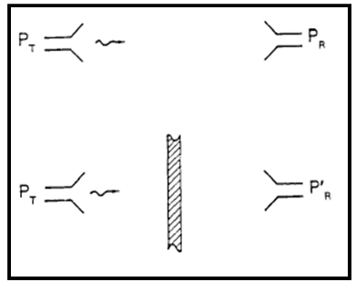 | Figure 1. Insertion loss technique[13] |
 the material is in the far field. If the distance between the transmitting antenna and the material is equal or smaller than the wave
  the material is in the near field.
3. Test Methods and Standarts for Electromagnetic Shielding Effectiveness
3.1. Test Methods Using Plaque Measurements
3.1.1. ASTM ES-7 Dual Chamber Test Fixture
- The dual Chamber test fixture described in ASTM ES-7 is widely used in near field measurements (Figure 2) This fixture requires small sample sizes. A transmitting antenna mounted in one chamber and a receiving antenna mounted in other chamber. Measurements are made using the insertion loss technique. The power radiated between the antennas with no sample is measured and determined as Pr. Then the power radiated between the antennas through the sample is measured and determined as P’r. Last EM SE is defined by the formula shown in Eq.1. This system has some advantages as, not requiring expensive chambers and being fast and simple. However it has some disadvantages as the box shows frequency-dependent behaviour due to resonances as a result of chambers’ physical dimensions[14].
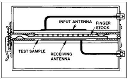 | Figure 2. ASTM ES-7 Dual Chamber Test Fixture[14] |
3.1.2. ASTM ES-7 Coaxial Transmission Line
- ASTM ES-7 Coaxial Transmission Line test fixture has a center and a outer conductor. The center conductor has an enlarged diameter center and tapered to the ends to make connection with the center pin of a BNC connector. The outher conductor has been expanded to the appropriate dimensions to maintain 50 ohms impedance. It also has longitudinal slits along its middle sections to hold disk-shaped samples[14]. The EM shielding effectiveness is measured according to the insertion loss technique as shown in Eq.1.For the sufficient measurement and to supply the electrical contact between the inner and outer conductors, the edges of the material sample must be painted with silver paint. This test fixture doesn’t give sufficient values for the samples as coatings and materials that have a buried conductive layer or high surface resistivity[15].
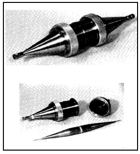 | Figure 3. ASTM ES-7 Coaxial Transmission Line[16] |
3.1.3. NBS (National Bureau of Standards) Flanged Coaxial Cell Test Fixture
- NBS Flanged Coaxial Cell Test Fixture looks like but does not rely on an electrical contact with the sample as the ASTM ES-7 Coaxial Transmission Line test fixture. Sample is mounted between the flanges in the middle of the test fixture. While transmitting the signal, the current does not place across the flanges and this eliminates the electrical contact problem with the sample. ’For this reason, this test fixture can be used for SE measurements for the samples which have an insulated surface as fabrics and fabric reinforced composites[15] The two, reference and load measurements are made for determining the EM SE. For the reference measurements, a disk sample of the material that has a diameter equal to the center conductor, and a ring sample that has a diameter equal to the outer conductor flange dimensions, are prepared. Reference samples are placed to the fixture and an incident power (P0) is measured with this reference sample. For the load measurement, a disk sample of the material that has a diameter equal to the outer conductor flange is prepared. Load sample is placed in the flanges and the transmitted power (P1) is measured. The shielding effectiveness of the material is calculated according to the Eq.1.
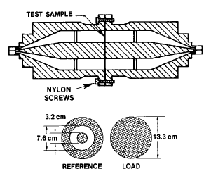 | Figure 4. NBS (National Bureau of Standards) Flanged Coaxial Cell[14] |
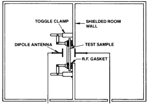
3.1.4. Modified MIL-STD-285 Test Method
- Modified MIL-STD-285, is one of the oldest method used for the shielding effectiveness measurements of the materials in plaque form. In this method, the sample is placed on the aperture of a shielded room wall. A transmitting antenna is placed one side of the aperture and a receiving antenna is placed the other side of the aperture. The measurement is done in two steps as done in insertion loss technique. First step is done without sample and the power received to the receiving antenna (P0) is recorded and the second step is done by inserting the sample on the aperture then the power received to the receiving antenna (P1) is recorded. Then the shielding effectiveness is calculated according to the equation 1.Several common problems that effect test repeatability, in the use of modified MIL-STD-285, are variations in sample surface resistance, aperture size, room and leakage and multiple reflections[17].
3.1.5. Dual TEM Cell (DTEM)
- Dual TEM Cell test fixture is the only one that can seperate the electric and magnetic field couples. Both the near field and the far field measurements can also be measured by this technique[17]. The Dual TEM Cell System consists of two TEM cells, coupled through an aperture. System has four ports as shown and numbered in Figure 5.
 | Figure 5. Modified MIL-STD-285 Test Method[14] |
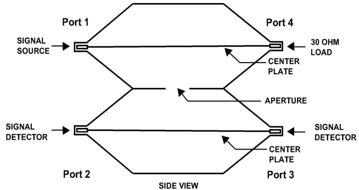 | Figure 6. Dual TEM Cell[17] |
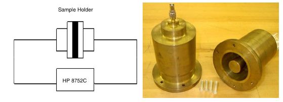
3.1.6. ASTM D 4935 Circular Coaxial Transmission Line Holder
- This technique is suitable for the SE measurements of flat and thin materials, especially for the composite materials. Plain wave shielding effectiveness measurements for high frequencies can be made with this set-up. The set-up is consisted of a sample holder with its input and output connected to the network analyzer. The sample is clamped between the halves of the sample holder. The holder is an enlarged, coaxial transmission line with special taper sections and notched matching grooves to maintain a characteristic impedance of 50 ohm throughout the entire length of the holder[12]. The measurements are made in two steps as reference and load measurements. The reference and the load samples are shown in Figure 7. SE is defined as the ratio of power received with the load specimen in place (P1) and with the reference specimen in place (P0).SE=10 log (P0/ P1)
 | Figure 7. ASTM D 4935 Circular Coaxial Transmission Line Holder[12] |
3.2. Enclousure Measurement Techniques
- The second technique used in measuring the electromagnetic shielding effectiveness of a material is, to place a receiving antenna in a prototype of a box made from the material and measure the power that transmits through the walls. In this technique the SE value is affected from the geometry and the size of the prototype and the electrical performance of the material sample. The advantage of this type of measurement is, to approximate closely the final electromagnetic performance of enclosure and as in the real world SE is effected by the shape, size of the enclosure and the multiple internal reflections[14]. So that the suitable measurement will be made for the real usage of the material[18]. But the disadvantage of this technique is to require very big sizes for some prototypes.
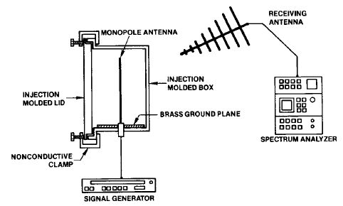
3.2.1. Injection Molded Enclosure Test Method
- The enclosure is 18X25X18 cm in size. Box and lid are molded from the sample materials to determine the shielding effectiveness of each material in a practical in-use situation. A 20 cm long transmitting antenna is placed on a brass ground and the transmitting antenna is mounted to a signal generator as shown in Figure 8. The SE is measured, first placing the lid and measured the power (P1) transmitted from the transmitting antenna to the receiving antenna. Second, removing the lid and measured the power (P0) transmitted from the transmitting antenna to the receiving antenna. Then the box is rotated around the axis of the transmitting antenna. The transmitted power is determined through the top of the box to the bottom of the box. So that, SE of all sides of the box can be determined.
 | Figure 8. Reference and load sample geometries[12] |
3.2.2. IEEE-STD-299
- This method can be used for measuring the shielding effectiveness of boxes bigger than 2 m in the frequency range of 9 KHz-100 GHz. It is not suitable for the boxes smaller than 2 m. This method can be used for the enclosures made from every kind of material as steel, copper, aluminium and fabric reinforced composites. According to the test procedure, first reference measurements must be made. For different frequencies, different antennas must be used. Test procedure depends on the measurement of the power that transmits from the transmitting antenna to the receiving antenna.
 | Figure 9. Injection Molded Enclosure Test Method[14] |
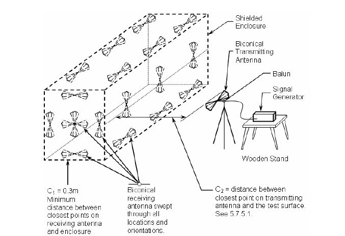 | Figure 10. IEEE-STD-299 |
4. Conclusions
- There are so many test methods for measuring the shielding effectiveness of materials in literature. These test methods differ in two main systems. One is, measuring the EMSE in the form of a flat thin, sheet or plate and the other is, measuring the completed enclosure made from the material. Both of the techniques use the insertion loss measurement technique. As a result of this study, the measurement values of plate tests and enclosure tests are different from each other. So that, for determining the test technique, the far-near field, material size, the frequency range and the place where the material will be used, must be considered. To use both systems (plaque measurement and enclosure measurement) is the best way for determining the shielding effectiveness of a material. So that the EMSE test results will be more meaningful and sufficient.It is determined that NBS Flanged Coaxial Cell Test Fixture is the best test method for the materials in plate form. While transmitting the signal, the current does not place across the flanges and this eliminates the electrical contact problem with the sample. For this reason, this test fixture can be used for SE measurements for the samples have an insulated surface as some fabrics and fabric reinforced composites.The all test methods presented in this paper, can be used for determining the EMSE of fabrics and fabric reinforced composites. A good test procedure is the one which is both meaningful and repeatable.