Bilal Zahid1, 2, Xiaogang Chen2
1Textile Engineering Department, NED University of Engineering and Technology, Karachi-75270, Sindh, Pakistan
2School of Materials, University of Manchester, M139PL, Manchester, United Kingdom
Correspondence to: Bilal Zahid, Textile Engineering Department, NED University of Engineering and Technology, Karachi-75270, Sindh, Pakistan.
| Email: |  |
Copyright © 2012 Scientific & Academic Publishing. All Rights Reserved.
Abstract
Textile composites are lightweight, strong as compared over the conventional materials and thus have found application in many areas, particularly in protective textiles. This research is a part of work carried out for the manufacturing and evaluation of riot helmet shells having continuous textile reinforcement. A single-piece continuous textile reinforced riot police helmet shells have been developed. Moreover, the developed helmets were impact tested and the results were compared with the simulated model results. These series of papers involves creation of a geometric model, simulation and evaluation. The current paper describes the development of a geometric model and its simulation in finite element software ABAQUS.
Keywords:
Helmet, Continuous Textile Reinforcement, Geometric Model, Simulation, Finite Element
Cite this paper: Bilal Zahid, Xiaogang Chen, Development of an Impact Simulation Model of Riot Helmet Shells, Journal of Safety Engineering, Vol. 2 No. 2, 2013, pp. 20-25. doi: 10.5923/j.safety.20130202.02.
1. Research Background
The research carried out is part of work for the creation and evaluation of riot helmet shells. The continuously textile reinforced helmet shells have been successfully developed from a5-layerangle-interlock fabric using vacuum bagging process[1]. Moreover, physical and mechanical properties of the developed composite structures from 5-layer angle interlock fabric have been calculated and analysed [2]. The developed single-piece continuously textile reinforced helmet shell can be viewed in Figure 1[1].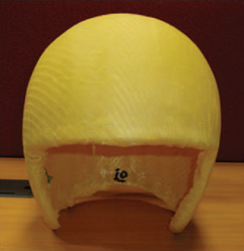 | Figure 1. Single-piece continuously textile reinforced helmet shell |
Furthermore, an impact test rig was developed based on an Instron drop weight impact tester Dynatup 8200 to evaluate the impact performance of produced helmet shells [3]. Sensors were mounted on top, back and side of the testing headform developed following the standard BS EN 960:2006[4]. The developed test rig can be viewed in Figure2. 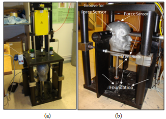 | Figure 2. Different views of the helmet test rig (a) front view (b) side view |
The literature review suggests that finite element analysis is a vital tool for the virtual experimentation, since a validated FE model from experimental results will give a deeper understanding [5, 6]. In current research, it was planned that in addition to the experimental analysis, a finite element (FE) method will be used to model helmet shells and to study the influence of the geometrical parameters on the performance of the helmet shells in FE software ABAQUS. ABAQUS was chosen for creating simulations due to its windows interface and also due to availability in University of Manchester.The series of papers involves creation of a geometric model, simulation and evaluation. The current paper describes the development of a geometric model and its simulation in finite element software ABAQUS. In future research papers, impact properties at different impact locations on the helmets shells are investigated physically through the helmet testing instrument and virtually by means of ABAQUS software.
2. Introduction
2.1. Brief Introduction of ABAQUS
ABAQUS is engineering software that provides facility to create ABAQUSmodels, to run and monitor the progress of analyses, and to evaluate the results from ABAQUS simulations[7]. In this study the ABAQUS/Explicit product was used which has three stages namely pre-processing, simulation and post processing. One of the advantages of ABAQUS/Explicit as used is that it can translate or import geometries in to the ABAQUS/CAE environment. Further, ABAQUS/Explicit is used for simulating impact problems[7]. Pre-processing is creating an input file for ABAQUS simulation in the ABAQUS/CAE environment. Simulation is run as a background process in which the ABAQUS/Explicit solves the numerical problem defined in the simulation. Post-processing is usually carried out by using a visualisation module of the ABAQUS/CAE processor. Results are calculated and analysed in post-processing. In finite element analysis, actual geometries of the structures have to be first discretised by using finite elements. Each element represents a particular portion of the physical structure. Finite elements are joined together by nodes and the collection of nodes and elements are knows as a mesh. The ABAQUS/CAE environment is divided into many different functional units known as modules.In each module a specific modelling task has to be assigned[7]. In the part module, parts are created either by sketching or by importing the geometry of the structure into ABAQUS/CAE environment. In the property module, a section is created and assigned to the parts. These sections contain material definitions for a particular region or part as required. An ABAQUS model has only one assembly and in the assembly module all the parts are positioned, instances (the replica of the parts) are created and positioned according to the global coordinate system to form an assembly. A step is a sequence for capturing change in a model. In the step module, steps are created and configured for analysis. These steps are directly related to the output request. There can be a number of steps in an ABAQUS model. In the interaction module, interactions within an assembly are created based on its mechanical properties. The behaviour of two different surfaces for instance, constraints and contacts are created in the interaction module. Loads, boundary conditions and predefined fields are applied in the load module. Loads and boundary conditions influenceon the results of the analysis and also they are step dependent. The mesh module is one of the most important modules by which finite element meshes are created onto the assembly. Mesh size and shape also has an effect on the analysis. Jobs are submitted for analysis and monitoring in a job module. The visualisation module provides a graphical display of the finite element models and results. In ABAQUS Lagrangian, material is used in dynamic analysis; due to this the elements remain attached to the meshes throughout the analysis and do not flow out of the element boundaries[7]. ABAQUS uses the central difference rule to integrate the equation of motion explicitly through time. It uses the kinematic condition of one increment to calculate the kinematic condition of the next increment.
3. Creation of Geometries for Impact Simulation
3.1. Riot Helmet Shell Geometry
The creation of the riot helmet shell geometry based on the developed helmet shells has been described in steps.
3.1.1. Generation of Point Clouds
Half helmet shell coordinates in form of (X, Y, Z) were entered into the Rhinoceros software one by one, as point clouds. The coordinates were inserted in 3D space as can be viewed inFigure 3.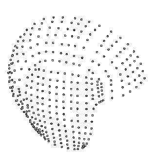 | Figure 3. Half helmet shell nodes |
3.1.2. Surface Generation
Points were joined together horizontally and vertically to form a half helmet shape. After these joining processes, surface generation was carried out individually in all the rectangles of the half head form. The reason for doing this individually was the curvature of the helmet shell which varies at different locations as shown inFigure 4.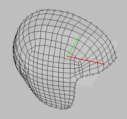 | Figure 4. Surface generation of half helmet shell |
3.1.3. Thicknesses to Shell Surface
The next step was to give thickness to the half shell. The helmet shell manufactured has an average thickness of 1mm[1]. A scaling command was used to give thickness to all squares having surface generated as 1 mm of the shell as in Figure 5.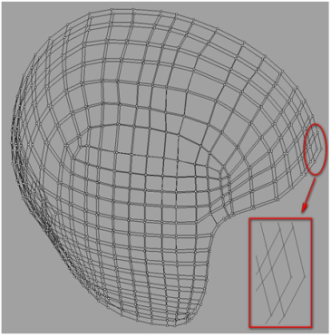 | Figure 5. Half helmet shell with thickness 1 mm |
3.1.4. Mesh Generation
The next stage was the generation of mesh in each rectangle of the half helmet shell shape. Individual surfaces were generated in the top and on the bottom layer of the helmet shape and not in between the layers.Figure 6 shows the surface generated of half helmet shell shape.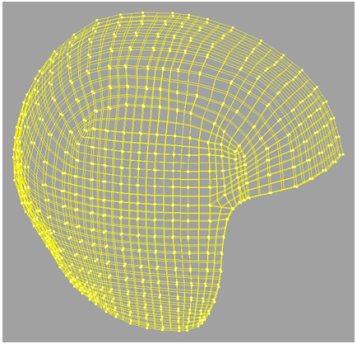 | Figure 6. Half helmet shell shape with individual meshing |
3.1.5. Mirror to Complete Helmet Shell Shape
In the last stage, another half of the helmet was mirrored in the Rhinoceros software to achieve a full riot helmet shell shape with a uniform thickness of 1 mm as in Figure 7 (a)& (b) . After this, the complete helmet shape was exported in *.iges format and imported to ABAQUS as a solid part shown in Figure 8. 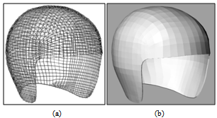 | Figure 7. Riot full helmet shell shape in Rhinoceros (a) without render (b) with render |
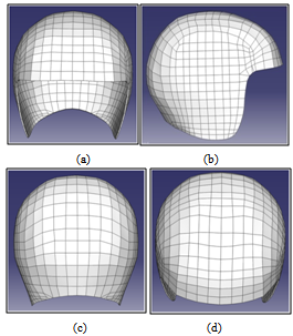 | Figure 8. Helmet shell views in ABAQUS (a) front (b) side (c) back (d) top |
3.1.6. Creation of Internal and External Faces
The helmet shell developed in Figure 8 was imported in *.iges format as a solid part with a large number of faces which were developed during the creation of the geometry of this shape. Every face was joined precisely with the neighbouring ones, leaving the impact position area and the edge of the helmet shell as can be viewed in Figure 9. The edges were left in order to have nodes on the edge which can be used for applying boundary conditions. 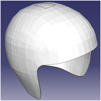 | Figure 9. Helmet shell with combined faces |
The creation of internal and external faces is one of the most important aspects of the work carried out in order to have homogeneous meshing throughout the helmet shells. In Figure 9, a portion is left on the internal and the external faces at the site of impact. At this particular area, high density meshing can be obtained on the contact position and uniform meshing elsewhere on the helmet shell geometry.This technique of meshing has been used in all the models developed for this study.
3.2. Geometry of Impactor Shape
The impactor was designed in ABAQUS as in Figure 10, as a flat rigid cylindrical impactor. The dimensions of the impactor were 67.5 mm height and 25 mm diameter, similar to the impactor used in experimental tests.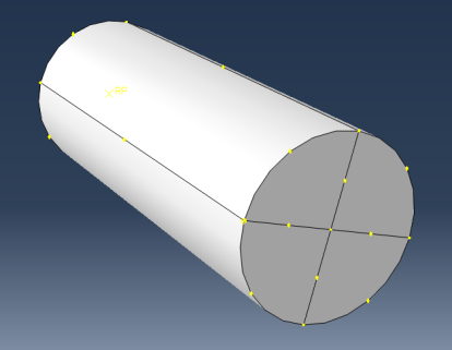 | Figure 10. Flat impactor |
3.3. Geometric Model of Headform
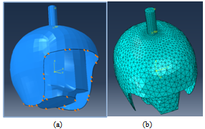
The headform coordinates were taken from EN 960:2006[4]. The headform standard is also used in the by British riot helmet shell standard[8], where the helmets are also placed on the headform for impact testing. Headform coordinates were entered via Rhinoceros software and the steps discussed above for helmet shell creation were repeated. The headform was made as a solid material having aluminium properties. Headforms made of aluminium are commonly used by several authors[9-11]. Different views of the developed headform are shown in Figure 11.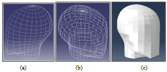 | Figure 11. (a) Half headform wire structure (b) Complete headform wire (c) Complete solid headform in ABAQUS |
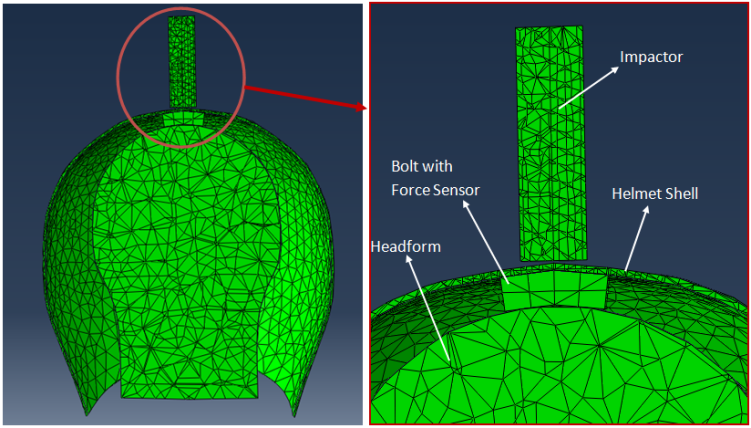
Further, a small part was created and attached on the top of the headform by means of a tied command in ABAQUS. This was a replica of the force sensor used in experimental testing. In the physical experimental impact test, a force sensor was tied by a steel bolt beneath the helmet shell and attached to the headform. A force sensor surface having a thickness 25 mm, similar to the physical force sensor was designed and simulated as shown in Figure 12.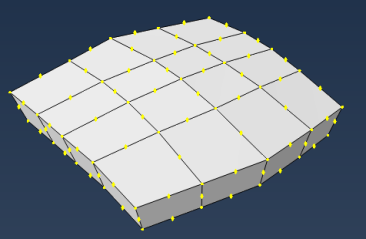 | Figure 12. Surface representing force sensor |
4. Transverse Isotropic Properties
Transverse isotropy is a sub-class of the orthotropic property of materials in which materials have one plane as an isotropic plane[7,12,13]. In the experimental testing, Kevlar based through the thickness angle-interlock fabric was used for making helmet shells[1]. Due to geometry of the Kevlar composite angle-interlock fabric, it was decided to assume the material as being transversely isotropic. While assigning the simulated helmet shell properties, the thickness of the helmet shell was assumed to be as an isotropic plane. Figure 13 shows plane 2-3 as a transverse isotropic plane. 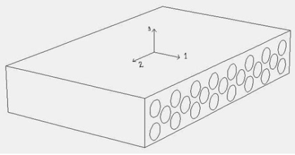 | Figure 13. Transverse isotropic plane |
In the transverse isotropic class of orthotropic material, there are only 5 independent constants. The properties obtained from the work carried out byZahid and Chen[2] and were calculated according to the method used by several other authors[7,12,13].Density of Kevlar Composite Material, ρ = 1.229 gm/cm3Modulus in the weft direstion, E1 = 36938.301 MPaModulus in the warp direction, E2 = E3 = 7793.701 MPaPoisson Ratio (weft to warp),ν12 = ν 13 = 0.356Poisson Ratio (warp to weft),ν21 = 0.075Poisson Ratio (warp to thickness), ν23 = 0.108Inplane Shear Modulus, G21 = G12 = G13 = 1379.255 MPaInplane shear warp to thickness, G23 = 3516.808 MPaWhere,ν12 = (vf x Vf) + (vr x Vr)ν21 = (E2 / E1) x ν12ν23 = ν12 x ((1 – ν21) / (1- ν12))G23 =[(E2) / {2x(1+ ν21)}] Vf is Poisson ratio of the fibre material, Kevlar 49[14] = 0.36Vr is Poisson ratio of the matrix material, Araldite LY5052 and Aradur 5052[15]= 0.35
5. Meshing and Boundary Conditions
In this model a tetrahedral shape (shown in Figure 14) of mesh is used because it is the most suitable mesh shape for three dimensional complex parts and almost every solid three dimensional part can be made by this mesh shape[7]. Further, Encastre boundary conditions were given at the neck and helmet shell edge as shown in Figure 15.A cross sectional view of the simulated model in Abaqus CAE environment can be viewed in Figure 16.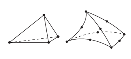 | Figure 14. Tetrahedral shape |
 | Figure 15. Simulation showing (a) Boundary conditions (b) Meshed parts |
 | Figure 16. Cross-sectional view of the simulated model in ABAQUS |
6. Creation of Finite Element Models for Different Impact Locations
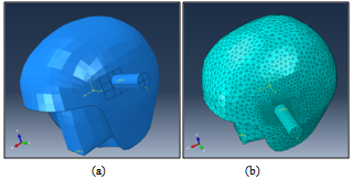
The impact energy levels were set to be 5.5 Joules, 15.5 Joules and 25.5 Joules with the flat cylindrical impactor having a mass of 4.66 kg. These levels of energy were set in order to compare the model with the experimental testing carried out for the model verification. Furthermore, the helmet shell was impacted at three different locations i.e. the top location, the side location and at the back location. For this purpose more models were created in order to simulate the impact at different locations. From the test simulation it was noted that a 3ms analysis time is sufficient to investigate the impact performance of developed shell models. Impact locations can be shown at three different models in Figure 17, Figure 18&Figure 19.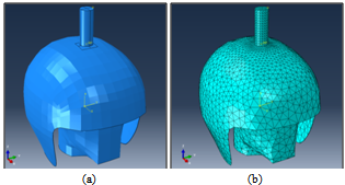 | Figure 17. Schematic illustration of the FE impact models for Top impact location: (a) Assembly form (b) Meshed form |
 | Figure 18. Schematic illustration of the FE impact models for Side impact location: (a) Assembly form (b) Meshed form |
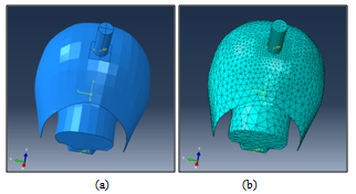 | Figure 19. Schematic illustration of the FE impact modelsfor Back impact location: (a) Assembly form (b) Meshed form |
7. Simulated Results from the Developed Simulations
The simulated results will be published in the future papers. However, in order to give a glimpse for the simulation working status some of the results are discussed.The simulation was focused extracting results based on the energy absorption and force attenuation.Designed helmet shells were impacted at different impact locations with three different energy levels. These energy levels were similar to the physical impact conditions. 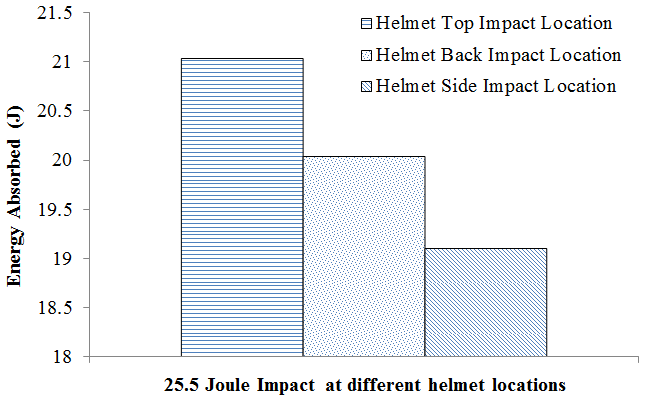 | Figure 20. Energy absorption at different impact locations |
These preliminary results shows that the helmet top impact location is absorbing more impact energy than the helmet side location and helmet back location for an impact energy of 25.5 Joule.
8. Conclusions
In this paper, geometric models of riot helmet shells have been created and impact simulations have been established. In total, 9 models have been successfully created. Formation of models in ABAQUS has provided the ability to analyse the impact performance and properties of riot helmet shells in an effective way. In future work, the simulated models will be validated by the experimental data. Impact performance at different helmet location with different impact energy levels on the helmet shells can be evaluated and validated. This series of papers involve the development of a geometric models and its simulation in finite element software ABAQUS. Future papers, will discuss the simulated models results and its validation from the experimental results.
ACKNOWLEDGEMENTS
This study was financially supported by NED University of Engineering and Technology, Karachi, Pakistan.
References
| [1] | Zahid, B. and X. Chen Manufacturing of single-piece textile reinforced riot helmet shell from vacuum bagging. Journal of Composite Materials, 2012. DOI: 10.1177/0021998312457703. |
| [2] | Zahid, B. and X. Chen Properties of 5-layer angle-interlock Kevlar-based composite structure manufactured from vacuum bagging. Journal of Composite Materials, 2012. DOI: 10.1177/0021998312463457. |
| [3] | S Min, et al. Moulding of single-piece woven fabrics for protective helmets --- A review and future work. in Proceedings to the 4th World Conference on 3D Fabrics and Their Applications. 2012. Aachen, Germany. |
| [4] | The European Standard, Headform for use in the testing of protective helmets BS EN 960:2006. |
| [5] | Kormi, K. and R.A. Etheridge, Finite element analysis - application of the finite-element method to simulation of damage to the human skull as a consequence of missile impact on a multi-layered composite crash helmet J. Biomed, 1992. 14. |
| [6] | Her, S.-C. and Y.-C. Liang, The finite element analysis of composite laminates and shell structures subjected to low velocity impact. Composite Structures, 2004. 66: p. 277-285. |
| [7] | The University of Manchester. http://www.applications.itservices.manchester.ac.uk/medialibrary/docs-abaqus/GET_STARTED.pdf. Series 2009 [cited 2010]. |
| [8] | Malbon, C. and J. Croft, PSDB protective headwear standard for UK police (2004) public order helmets, in Police Scientific Development Branch 2004. |
| [9] | Becker. Guided fall impact test devices http://www.smf.org/docs/articles/dot_reply_08/mo_tw2.pdf. Series 1997 [cited 2011]. |
| [10] | Mills, N.J., Protective capability of bicycle helmets. group.bmj.com, 2011. 24. |
| [11] | Mills, N.J. and A. Gilchrist, Oblique impact testing of bicycle helmets. Imternational journal of impact engineering, 2008. 35. |
| [12] | Kaw, A.K., Mechanics of composite materials. 2nd ed 2006: Taylor & Francis. |
| [13] | Mallick, P.K., Fiber-reinforced composites materials, manufacturing and design. 3rd ed 2008: Taylor & Francis Group, LLC. |
| [14] | Kevlar. Technical Guide Kevlar Aramid Fiber. Series 2011 [cited 2011] Available from: http://www2.dupont.com/Kevlar/en_US/assets/downloads/KEVLAR_Technical_Guide.pdf. |
| [15] | Huntsman. www.huntsman.com. Series 2010 [cited 2011]. |
 Abstract
 Reference
 Full-Text PDF
 Full-text HTML