Chigbogu G. Ozoegwu1, Christian. C. Nwangwu2, Chigozie F. Uzoh3, Arinze V. Ogunoh4
1Department of Mechanical Engineering, Nnamdi Azikiwe University PMB 5025 Awka, Nigeria
2Department of Metallurgical and Materials Engineering, Nnamdi Azikiwe University Awka
3Department of Chemical Engineering, Nnamdi Azikiwe University Awka
4Department of Industrial Production Engineering, Nnamdi Azikiwe University Awka
Correspondence to: Chigbogu G. Ozoegwu, Department of Mechanical Engineering, Nnamdi Azikiwe University PMB 5025 Awka, Nigeria.
| Email: |  |
Copyright © 2012 Scientific & Academic Publishing. All Rights Reserved.
Abstract
There is no single cause of undesirable vibrations occurring in rotating machinery. Poor operating conditions like loose mechanical parts, faulty impellers, faulty bearings, faulty gears, unbalanced machine elements, whirling and unbalanced shafts intensify vibration in rotating machines. In this work rotational unbalance was singled out as a cause of vibration and its nature, causes, effects and remedies explored and explained. Analytical equations are derived for both cases of single and double plane balancing of experimentally determined unbalance. The double plane balancing equations (10, 11 and 12) are novel to this work. With the derived balancing equations, an operator could avoid the difficult-to-understand, difficult-to-use and error prone graphical approach. In the modern world’s industrial set-up, productivity is improved by integrating high-speed computers into the process of production. Based on this need a general MATLAB program was written for quick solution of experimental double plane balancing problems. Three exercises drawn from a standard text were used to illustrate the usefulness of the derived equations.
Keywords:
Single Plane Balancing, Double Plane Balancing, Centrifugal Forces, Principal Axis
Cite this paper:
Chigbogu C. Ozoegwu, Christian. C. Nwangwu, Chigozie F. Uzoh, Arinze V. Ogunoh, "zPure Analytical Approach to Rotational Balancing", Journal of Safety Engineering, Vol. 1 No. 4, 2012, pp. 50-56. doi: 10.5923/j.safety.20120104.01.
1. Introduction
International Standards Organization (ISO) as seen in[1] defines unbalance as that condition which exists in a rotor when a vibratory force or motion is imparted to its bearings as a result of centrifugal forces. Unbalance is the uneven distribution of mass about a rotor’s rotating centreline. In other words rotational unbalance results when the axis of rotation of a rotor system is not coincident with the principal axis of inertia. This eccentricity occurs whenever there is geometric, material and property asymmetry about a rotor’s rotational axis. Unbalance in rotating machinery causes dynamic forces that bring about vibration and intensification of stresses at the bearing and other receivers. When unbalance appears to be in a single axial plane such that the principal axis of rotation is displaced parallel to the geometric centreline, static unbalance results. In other cases called dynamic unbalance non-zero couple set-up by centrifugal forces occur at the bearings[2]. Dynamic unbalance will result when the principal axis of rotation and geometric centreline are neither parallel nor touching or when it appears that unbalance occur in multiple axial planes. Engineers deal with unbalance by addition or removal of matter such that the geometric axis of rotation approaches the principal axis of rotation in alignment and proximity. Static unbalance is corrected by addition or removal of correction weight in the plane of the unbalance while dynamic unbalance is corrected by addition of two appropriate weights in two arbitrarily chosen planes[2, 3]. There are many causes of unbalance in rotating machinery. Any form of eccentricity and non-uniformity in a machine element causes unbalance. During manufacturing process imperfections such as density variation, porosity and blowholes occur. Human error in manufacturing process results in fabrication errors like eccentric machined part, misaligned assembly and misshapen castings. Cumulative assembly tolerance is also one of the causes of rotating unbalance. Rotating machinery in operation that is originally balanced with time becomes unbalanced due to distorting rotational stresses and temperature changes. Necessary features like keys, key ways, bolts, nuts, rivets, welds and cranks added to practical machines increases the propensity to unbalance. Accumulation of deposits in a running machine plays a negative role in the balancing condition of the machine. In a corrosive environment the rotor shape may get compromised leading to unbalance. Increasing rotational speed increases the risks associated with both unbalance and whirling[1]. Unbalance in rotating machinery almost certainly occurs due to upper limit placed on the degree of manufacturing precision by human error.Unbalance causes sustained vibrations in rotating machinery. Unbalanced forces in a rotating machinery are harmonic of form  thus producing harmonically fluctuating fatigue stresses which causes aggravated damages to the rotating shafts, bearings, mounting frames, foundation and sometimes neighbouring machinery. Noise is one of the undesirable attributes of unbalance. Vibrations in rotating machinery get transmitted to the human operator and causes discomfort. The following effects on the human operator have been observed at various operating frequency ranges: motion sickness (0.1-1Hz), blurring vision (2-20Hz), speech disturbance (1-20Hz), interference with tasks (0.5-20Hz) and after-fatigue (0.2-15Hz) as seen in[3]. Unbalance and sequel vibrations increase the cost of running an industry in terms of reduced machine life, reduce duration between outages, increased spare parts stock , increased inefficiency and imprecision of produced parts . It becomes clear that unbalance must be dealt with from the stand-point of problems stemming from it.Through creative practice, engineers try to minimize the effects of harmful phenomena that cannot be eliminated. Rotational unbalance is one of such phenomena but fortunately it could be minimize to levels where it does not present as a major source of problem for the machinery and the operators. The source-path-receiver concept could be utilized in managing the vibrations induced by unbalance. Vibration is considered to be handled at the source when balancing procedures are carried out on the unbalanced rotor[3]. When design and incorporations are carried out to minimize the effect of vibration on the receivers, vibration will be considered controlled at the receiver. Vibration control at the receiver could be achieved by natural frequency design, damping, introduction of vibration isolators and introduction of dynamic vibration absorbers. Method of natural frequency was used to preclude the possibility of resonance in a building frame by designing the frame to have a natural frequency above the highest operational speed of a mounted motor[4, 5, 6]. If rotating machinery has a low natural frequency then resonance and instability may present a source of concern depending on the speed of start-up. A slow start-up requires damping to deal with any possible resonance especially in situation where whirling is an added concern. Unbalance is normally determined experimentally. The magnitude and location of balancing force is normally determined graphically. This graphical approach to double plane balancing is a long process that requires high level of expertise. It is difficult-to-understand, difficult-to-use and error prone. A number of analytical equations (equations (10, 11 and 12)) are generated in this work to overcome the challenges of graphical approach to double plane balancing.
2. Analytical Equations to Rotational Balancing
2.1. Single Plane Balancing
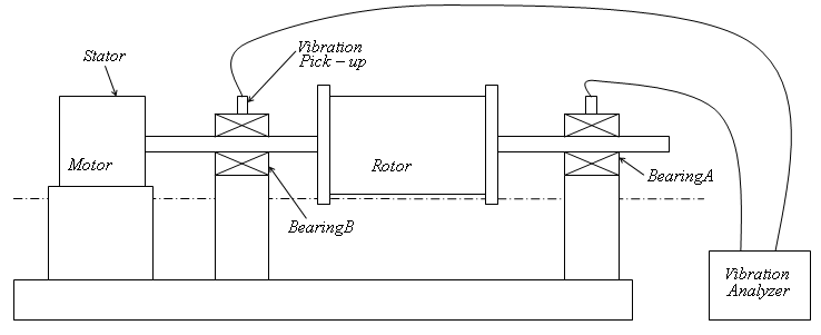
Unbalanced mass could come in the form of machine elements such as discs that have their centre of mass not coinciding with the geometric centre. Unbalance in such a machine element could quickly be noticed by it being mounted on a rigid shaft that is in turn mounted on a pair of low friction bearings and rotated in a given direction. If a mark given to the disc settles at the same location in successive rotations then there is unbalance. The magnitude and location of this unbalance could then be determined by running the rotor at a constant speed and measuring either of the reactions at the bearings. Such an arrangement is as shown figure1 below;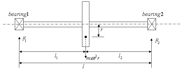 | Figure 1. A Single plane balancing problem |
 | Figure 2. Experimental set-up for single plane balancing |
Moments taken about bearing 2 results in | (1a) |
 | (1b) |
Where the unbalance  could be calculated from equation (1b) being that every other variable is known. The unbalance is corrected by adding a mass such that the original unbalance is cancelled. The unbalance could also be corrected by removing (drilling say) a mass at the location of the unbalance.
2.1.1. Single Plane Balancing Using Vibration Analyzer
The use of vibration analyzer helps to avoid the unreliable trial and error method of single plane balancing. An experimental set-up utilizing the vibration analyzer is as shown in figure2. In order to use the vibration analyzer for single plane balancing a summary of the procedure as seen in[3, 7] is presented in steps that follows;● Coincident phase marks are made on the rotor and stator while the rotor is static.● A vibration pick-up is place in contact with the disc-carrying bearing that is placed between the rotor and the stator.● The vibration analyzer is set at a frequency that corresponds with the angular velocity at which the test is run.● The rotor is run at the test speed  .● Vibration signal
  caused by the original unbalance as displayed by the indicating meter of the vibration analyzer is taken note of.● Under a stroboscope light fired by the vibration analyzer at its set frequency the reference mark on the rotor appears stationary with a phase lag
  and taken note of●The rotor is stopped, a known trial weight
  attached to it and the foregoing steps repeated to obtain vibration amplitude
  at a phase lag
  due to combined unbalance of rotor and trial weight.A typical vector diagram is constructed as shown in figure3 The vector
  which is the unbalance due to the trial weight and the angle
  which is the angle between
  and
and  are seen from the vector diagram to be
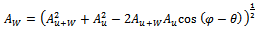 | (2a) |
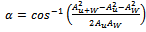 | (2b) |
It is assumed that at constant radial distance vibration amplitude is proportional to magnitude of unbalance producing it. The magnitude of the original unbalance becomes | (3) |
For complete static balance a balancing force  of same magnitude as
  will be placed at the same radial distance as W and at an angle
  counter clockwise from
  .
.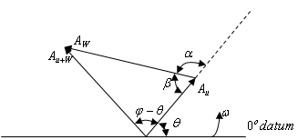 | Figure 3. Vector diagram for single plane balancing |
Example1: in order to determine the unbalance in a grinding wheel, rotating clockwise at 2400rpm, a vibration analyzer is used and amplitude of 4mils and a phase angle of 45 degrees are observed with the original unbalance. When trial weight W=4 oz is added at 20 degrees clockwise from the phase mark, the amplitude becomes 8mils and the phase angle 145 degrees if the phase marks are measured from the right hand horizontal, calculate the magnitude and location of the necessary balancing weight[3].Solution: Given data; 
 Using equation (2a)
 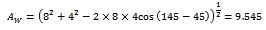 From equation (3)
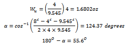 Since the derivation is made and vector diagram drawn assuming counter clockwise rotation thus the balancing weight must be added 55.6 degrees clockwise of the position of the trial weight. For static balancing the weight 1.6802 oz must be added at (55.6+20=75.6) degrees clockwise of the right horizontal.
 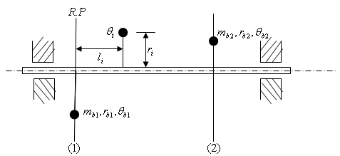 | Figure 4. Double plane balancing problem |
 | Figure 5. Illustration of a double plane balancing problem |
2.2. Double Plane Balancing
Single plane balancing is approved to be satisfactory for rotors of thin rigid disc type but unreliable for rotors of elongated rigid body type[3]. For rotors of latter type double plane balancing is recommended and consists of proper addition of appropriate weights in any two planes[8, 9]. Another name for double plane balancing is dynamic balancing since it results in the cancellation of both unbalanced forces and moments[9]. Another practical situation that needs dynamic balancing is the case where known eccentric masses are positioned round a rotor in different planes and each mass  exists at an axial, radial, and angular location
  (relative to reference plane),
  and
and  (relative to one of the unbalanced masses) respectively. If the arbitrarily chosen planes are
  and
and  as shown in figure4 and the rotor is to be dynamically balanced by placing two masses
  at radii
  and
and  at angular locations
  and
and  in the chosen planes then the following derivation follow. The total unbalanced becomes
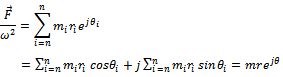 | (4) |
Introduction of balancing masses at their planes will result in static balance according to the equation;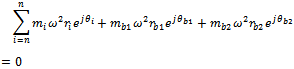 | (5) |
Equation(5) results in the two equations (6a)
(6a) | (6b) |
Moments taken about the reference plane while assuming that that the balancing mass  lies on it gives
 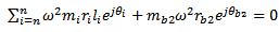 | (7) |
This results in the two equations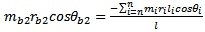 | (8a) |
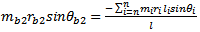 | (8b) |
From the equations(6 and 8) the following equations | (9a) |
 | (9b) |
are derived. Dividing equation(8b) with equation(8a) gives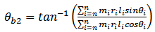 | (10) |
Dividing equation(9b) with equation(9a) gives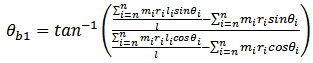 | (11) |
From equations(8-11) it becomes that | (12a) |
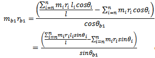 | (12b) |
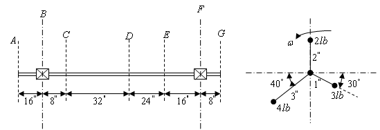
With equations (10-12) dynamic balancing can be achieved.Example2: weights 2lb, 4lb, and 3lb are located at radii 2in., 3in., and 1in. in the planes C, D, E, respectively, on a shaft supported at bearings B and F as shown below. Find the weights and angular locations of the two balancing weights to be placed in the end planes A and G so that dynamic load on the bearings will be zero[3].Solution: If angular positions are measured relative to mass in plane C then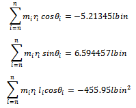
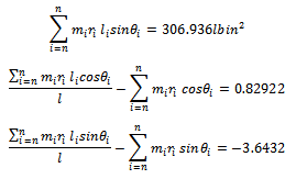 From equations (10-12) the solution becomes
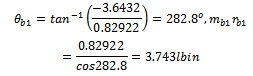 And
And  If the radial position
  are chosen then a mass of 1.8715lb at 282.8 degrees and 2.645lb at 326.1 degrees are needed in planes A and G respectively.
2.2.1. Double Plane Balancing Using Vibration Analyzer
The key idea here is that the overall unbalance can be replaced by two unbalanced weights  and
and  at the left and right planes respectively of the unbalance[3]. The same procedure as carried out for the case of single-plane-balancing is executed with a fundamental difference that two trial weights
  and
and  are exclusively added to the left and right plane respectively. Figure6 below is illustrative of the experimental set-up. It amounts to more experimental convenience during attachment of trial weights to choose two planes at the end of the rotor. Each of the unbalances
  and
and  has forced vibration effects on the two bearings that support the shaft that carry the rotor. The deduction from the last sentence is that vibration at bearing “i” due to excitations
  and
and  as measured by the vibration analyzer is
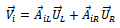 | (13) |
Where equation(13) is to be seen from the vector point of view since there is always a phase lag between excitation and response. The coefficients  where
where  captures the effect on vibration at bearing
  due to excitation at the plane
  . Using equation (13) the measure of vibrations at the bearings due to original unbalance at the operating speed of the rotor is
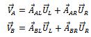 Which put in matrix form becomes
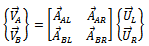 | (14) |
With a known trial weight  added at know angular and radial location on plane
  and the same procedure repeated the equation that results is
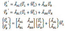 | (15) |
Equations (13) and (14) taken together gives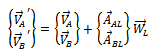 | (16) |
Re-arranging gives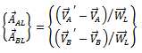 | (17) |
A known trial weight  added at know angular and radial location on plane
  and the same procedure repeated results in a similar equation
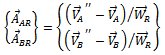 | (18) |
Equation (14) upon the substitution of equations (17) and (3.f) gives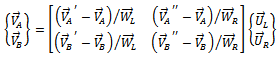
 | Figure 6. Experimental set-up for dynamic balancing |
Table 1. Data obtained for a two-plane balancing problem
 |
| |
|
Upon the process of matrix inversion the solution becomes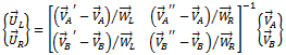 | (19) |
This gives the original unbalance in the rotor which at this point is balanced by placing weights  of equal magnitude but
  out of phase with
  at the same radial location as
  where
where  . At this point a MATLAB program that turns out the vector
  when relevant data are imputed is presented and has the general form
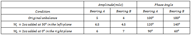
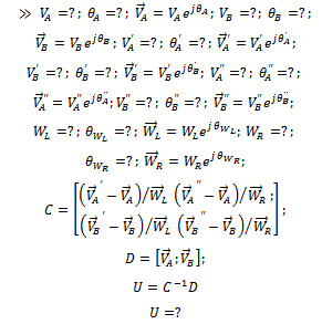 Example3: The data obtained in a two-plane balancing procedure are given in a table below. Determine the magnitude and angular position of the balancing weights, assuming that all angles are measured from an arbitrary phase mark and all weights are added at the same radius[3].Solution: MATLAB program based on equation (19) that solves the problem together with the solution is as displayed>> a=5;Da=100;Va=a*exp(j*Da*pi/180);b=4;Db=180;Vb=b*exp(j*Db*pi/180);a1=6.5;Da1=120;Va1=a1*exp(j*Da1*pi/180);b1=4.5;Db1=140;Vb1=b1*exp(j*Db1*pi/180);wl=2;Dwl=30;Wl=wl*exp(j*Dwl*pi/180);wr=2;Dwr=0;Wr=wr*exp(j*Dwr*pi/180);va11=6;Da11=90;Va11=va11*exp(j*Da11*pi/180);vb11=7;Db11=60;Vb11=vb11*exp(j*Db11*pi/180);C=[(Va1-Va)/Wl (Va11-Va)/Wr;(Vb1-Vb)/Wl (Vb11-Vb)/Wr];D=[Va;Vb];U=C^-1*DU =2.7366 - 3.2275i-1.6426 + 1.3429iThus the original unbalance is
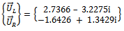 The required balancing forces become
3. Conclusions
It has been highlighted in this paper that rotational unbalance cannot be eliminated. It will amount to unfavourable cost to try dealing with rotational unbalance by investing heavily in achieving high precision in manufacture of machine parts. Rotating machinery in operation becomes increasingly unbalanced thus requires maintenance balancing with time. It is instructive to say that analytical equations (especially equations 10, 11 and12 which are unique to this work) outlined in this work would be handy for a field engineer charged with maintenance balancing of rotary machines. Three exercises were used to illustrate the usefulness of the analytical equations. The presented MATLAB program for double plane balancing would facilitate conversion of measured unbalance into balancing solutions thus increasing productivity.
References
| [1] | J. Lyons, Primer on Dynamic Balancing “Causes, Corrections and Consequences,” Presented at MainTech South’98, 2nd. December 1998. |
| [2] | A. N. Enetanya, Dynamic Problems in Design, Unpublished, 2011. |
| [3] | S. S. Rao, Mechanical Vibrations(4th ed.),Dorling Kindersley, India, 2004. |
| [4] | C. G. Ozoegwu, Structural Design by Natural Frequency Using FEM, Unpublished, 2011. |
| [5] | C. C. Ihueze, P. C. Onyechi, H. Aginam, C. G. Ozoegwu, Finite Design against Buckling of Structures under Continuous Harmonic Excitation, International Journal of Applied Engineering Research, 12 (2011) 1445-1460 |
| [6] | C. C. Ihueze, P. C. Onyechi, H. Aginam, C. G. Ozoegwu, Design against Dynamic Failure of Structures with Beams and Columns under Excitation, 2 (2011) 153-164 |
| [7] | J. Vaughan, Static and Dynamic Balancing using potable measuring equipment (2nd ed.), Bruel & Kjaer, DK-2850 Naerun Denmark. |
| [8] | R. L. Baxter, Dynamic Balancing, Sound and Vibration, Vol. 6 (1972) 30-33. |
| [9] | R. S. Khurmi and J. K. Gupta, Theory of Machines, Eurasia Publishing House (PVT.) ltd. Ram Nagar, New Delhi-110 0SS. |
 Abstract
 Reference
 Full-Text PDF
 Full-Text HTML