Jaeho Lee 1, Ducko Shin 2, Kangmi Lee 1, Kyeongho Shin 3
1Meteopolitan Railroad System Research Center, Korea Railroad Research Institute, Uiwang-si, Gyeonggi-do, 437-757, Korea
2Human Resources Development Team, Korea Railroad Research Institute, Uiwang-si, Gyeonggi-do, 437-757, Korea
3R&D Strategy Division, Korea Railroad Research Institute, Uiwang-si, Gyeonggi-do, 437-757, Korea
Correspondence to: Jaeho Lee , Meteopolitan Railroad System Research Center, Korea Railroad Research Institute, Uiwang-si, Gyeonggi-do, 437-757, Korea.
| Email: |  |
Copyright © 2012 Scientific & Academic Publishing. All Rights Reserved.
Abstract
The most important issue in evaluating a lifespan extension is to determine the validity and the efficiency to theextension. This can be calculated via cost-benefit analyses involving different kinds of failure scenarios. In case of railway, a similar situation often occurs in determining whether to introduce new installations or just maintain existing equipment by installing spare parts. In this study, a method for extending the lifespan of signalling installations that are more than 20 years old will be presented. We specifically focus on the case where there is no available reliability data, which may include information pertaining to the failure rate of the component unit or other failures that occur during operation. As a means of validating the service life extension, a period of non-failure assurance testing should be mandated, a test time and an accelerating coefficient for accelerated assurance testing should be calculated, and also an assessment model for accelerated assurance testing should be developed. The proposed model is an effective method to establish a future maintenance policy for railroad operators who manage deteriorated signalling equipment.
Keywords:
Reliability Assessment, Failure Rate, Lifespan, Signalling Equipment, MTBF
Cite this paper:
Jaeho Lee , Ducko Shin , Kangmi Lee , Kyeongho Shin , "Method of Expected Lifespan Assessments for Deteriorated Railroad Signalling Equipment", Journal of Safety Engineering, Vol. 1 No. 3, 2012, pp. 43-49. doi: 10.5923/j.safety.20120103.02.
1. Introduction
To date, the concept of lifespan assessment and extension has been used only in limited situations, such as for nuclear power plants and huge system plants, but it will ultimately probably be extended to other industries. The most important motivator in this context is cost. In Japan, the designed lifespan of nuclear power plants has increased several times during their operation, and in America the lifespan of weapons systems has been successfully extended. However, in a small-scale system, such as for most electrical and electronic goods, new designs or upgrades have been the norm, rather than operating life extensions. However, issues have recently been raised in these areas, such as the costs associated with end-of-life components, new designs that are far more expensive than substitute products, and replacements that are difficult to source. The most important motivation for considering extensions of lifespan is that the required cost-benefit analysis is often very efficient. Recently, many problems have occurred in railroad systems. Issues arise when new equipment are introduced due to the procurement of new components such as electronic signalling equipment. Under such circumstances, decisions must be made regarding whether or not to replace equipment that may already be in use[1][2]. In this paper, we calculate the residual lifespan of obsolete signalling equipment that is designed for long-term use without existing reliability data from continuous monitoring. Such data may include the failure rate per unit part, or in-operation failure information. In addition, we verify our predictions with a reliability test. Using this procedure, the reliability per unit part of the signalling equipment is calculated with MIL-HDBK -217FN2, and the residual lifespan is calculated assuming that the calculated and predicted lifespan is equal to the designed lifespan. Then, the ratio can be calculated depending on the failure mode of the signalling equipment. We use the parameter presented in the 217F Plus document to calculate the remaining life.We evaluate the remaining lifespan by using the calculated remaining lifespan function and we then confirm whether the resulting value is consistent with published data about extended lifespan.
2. Lifespan Diagnoses for Signalling Equipment
For the lifespan diagnosis of superannuated signalling equipment that is used over the long term, we diagnose the equipment at the level of component parts when reliability information is not available, as shown in Figure 1. We also predict the failure rate of the equipment and the MTBF (Mean Time BetweenFailure). Subsequently, we calculate the residual lifetime by assessing the failure pattern of electronic equipment in the system under test, and we develop a reliability test model to confirm the remaining future operating time. On the basis of these procedures, we conduct a reliability test (the Accelerated Life Test or the Accelerated Stress Test). 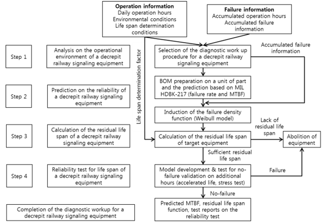 | Figure 1. Procedure for diagnostic workups on deteriorated signalling equipment |
2.1. The Reliability of Signalling Equipment
The reliability of signalling equipment that is composed of electronic parts can be quantified by the MTBF and MTBSF. The MTBF is the mean time between failures in the system and equipment during the device lifespan, and the MTBSF is the mean time between service failures in the system and equipment during the device lifetime. Therefore, the differences between the MTBF and MTBSF depend on how we define failure. Generally, the MTBF defines the failure in terms of a loss of designed system function, whereas service failures are defined on the basis of whether or not train delays are caused by failures. For example, power supply modules are often considered sub-equipment in railroad scenarios. Related failure modes may be common to both MTBF and MTBSF metrics because the failure results will lead not only to loss of functions but also to operational delays. Failures such as component failures of circuits, which feature different modules and components, can lead to operational delays to train schedules. Therefore, we assign them a certain weight and evaluate them consistent with the conditions of operation. FMEA (failure mode effects analysis) is a process for analysing the impacts of component failures and classifying failure rates to calculate the MTBF and MTBSF metrics. Generally, it is impossible to perform FMEA for each unit part in the case of equipment that was manufactured many decades ago. In such cases, it may be impossible to interview the personnel who designed the hardware. Therefore, only the MTBF can be used as a standard for lifespan evaluation through conservative data analyses. The MTBF is defined as the sum of the MTTF (Mean Time ToFailure), which is the reciprocal of the failure ratio (λ), and the MTTR (Mean Time To Repair), which is the reciprocal of the repair ratio (μ). However, it is possible that a MTTR on the order of 2 hours can be ignored if the MTTF is more than 10,000 hours. The MTBF can be expressed as the reciprocal of the failure ratio: | (1) |
The failure rate is evaluated as a constant because the failure characteristics of electronic components often involve random failure profiles. A random failure means that the system malfunctions randomly and without warning.
2.2. Reliability Predictions for Signalling Equipment
Reliability prediction is a process for quantifying the failure rate per unit part and predicting the MTBF. Consistent with the types of parts used, we predict the failure rate per unit part by using the equation listed in a standard such as MIL-HDBK-217FN2 or the similar. In addition, we sum the failure rates of the card combined with the parts and the equipment combined with the cards or, in the case of extra structures, we predict the failure rate and the MTBF for the whole device through the use of modelling[3]. Assuming that the predicted constant failure rate at the early stage theoretically does not change, the lifespan of the equipment should be predictable and constant. Hence, we should analyse the accumulated failure information collected from operational equipment and we should constantly manage any change in failure rates. However, the predicted failure rate should be used because the failure information collected from real operating systems cannot be guaranteed in the design and production process during a standard device life cycle. Thus, reliability prediction is the only method for assessing whether the quantitative reliability goals can be satisfied. Under such circumstances, as long as the types of components, capacity, quality, load, temperature characteristics, etc., are accurately recorded, the predicted failure rate is very similar to the failure rate as determined by using accumulated failure information that can be collected under real operating conditions. Therefore, the predicted failure rate is used as a standard to evaluate the reliability of equipment for which we lack accumulated failure information from operational settings [4].
2.3. Residual Life Assessments for Signalling Equipment
The residual life span is the period of time during which the reliability of the target equipment remains constant and favourable until the next planned preventive maintenance event. According to the theory of RCM2 (Reliability CenteredMaintenance) for the preventive maintenance of equipment that is composed of electronic parts that may include obsolete signalling hardware, replacement is defined as the goal of preventive maintenance. A preventive maintenance protocol should be applied in accordance with the maintenance policy of the operating agency. In the event that the agencies that manage the obsolete signalling equipment do not record and appropriately manage failure data, it is normal to calculate the reliability function of the exponential model on the basis of predicted reliability metrics. This theory is based on the premise that a constant failure rate, which is the basis for calculating the predicted value of the MTBF, is accurately matched with actual operational conditions. In more developed countries, rail operators often calculate this MTBF information, which more accurately reflects the state of equipment in use by periodically renewing the actual equipment failure rate data. Such operators will use methods such as FRACAS (Failure Reporting and Corrective Action System), to calculate the required number of cycles for preventive maintenance [5]. The residual lifespan of the equipment does not take into account the accumulated failure information of the equipment and does not represent the quantitative reliability standard of a device in the form of a residual lifespan evaluation standard. Accordingly, we assume that device failure information for equipment in the same application field can be interpreted using the general failure data published in the 217 Plus standard as issued by the RAC (Reliability Assessment Center) in the USA [6]. To derive a mathematical definition of the residual lifespan, the residual lifespan function  can be expressed in accordance with the reliability function, as shown in equation (2), by defining the state of the reliability metric immediately before reaching the zero survival state.
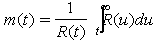 | (2) |
In equation (2), is the residual life span at . In other words, the mean value will persist until the current time and will continue to persist until the next arbitrary time point.In short;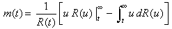 | (3) |
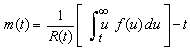 | (4) |
For obsolete railway signalling equipment, meaningful empirical data is generally unavailable. Accordingly, the residual function can be calculated by using similar equipment or empirical results. According to 217 Plus, the reasons for failure at the equipment level can be described using the ratio shown in Figure 2; the associated shape parameters values are listed in Table 1.| Table 1. Shape parameters categorized by failure cause |
| | Cause of failure | Rates | Shape parameter | | 1 | Parts defect | 0.298557159 | 1.62 | | 2 | Manufacturing defect | 0.188679245 | 0.96 | | 3 | Design | 0.096559378 | 1.29 | | 4 | Equipment management | 0.014428413 | 0.64 | | 5 | Wear-out | 0.107658158 | 1.68 | | 6 | Induced | 0.110987791 | 1.58 | | 7 | No defect | 0.154273030 | 1.92 | | 8 | Software | 0.028856826 | 0.70 |
|
|
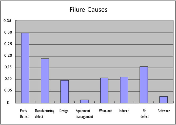 | Figure 2. Causes and rates of failure for electronic equipment |
Shape parameters, which determine the shape of the probability density function, are data from the 217 Plus document. These metrics can be used to analyze the failure patterns of general systems in terms of failure cause ratios. The shape parameter is the input for the Weibull function, which is derived from analyzing sets of accumulated failure data. The residual lifespan function for the obsolete signalling equipment can be calculated by using the designed lifespan, as listed in Table 1. To apply equation (4) to a device, we should convert it into the form of a Weibull function to reflect the accumulated failure information analytics from the 217 Plus document.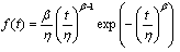 | (5) |
 | (6) |
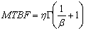
In equation (5), the shape parameter (β) is calculated according to a failure type. The scale parameter (η) is a substitute for the MTBF information of the device, as in equation (6), and can be used to calculate the form of the Weibull function and the scale parameter that corresponds to the failure mode of the device. This can be expressed as equation (7).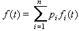 | (7) |
If equation (7) is substituted into the residual lifespan function, the final residual lifespan function can be expressed as equation (8).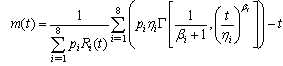 | (8) |
From equation (8), if we know the age of the device, we can predict the time at which the reliability reaches zero.In summary, we first use the predicted MTBF (the time at which about 63% of the EUT (Equipment UnderTest) will fail, as determined by the constant failure rate), and we evaluate this consistent with the standard failure pattern of similar equipment as listed in the RAC’s 217 Plus data. We can then calculate the average time until the reliability reaches zero; within a specified time period, this means that the probability of the equipment performing the desired functions will be exactly zero.
2.4. Verification of the Residual Lifespan
The most influential element in calculating the failure rate of electronic components is the operating temperature. In the equation for predicting failure rates for the component types listed in MIL-HDBK-217FN2, we include a factor of pi that is related to environmental conditions. If predicting it by the MIL-HDBK standard, we can clearly confirm the influence of temperature on electronic components [7]. The accelerated stress test and accelerated life test, will also be of relevance to temperature effects.The reliability test considers the activation energy according to the degree of temperature stress in each component and selects the acceleration factor accordingly. We then test the EUT over an accelerated test period. The differences between the accelerated life test and the accelerated stress test are determined by the time and behavior of the EUT. If the accelerated life test runs continuously until all the EUTs have malfunctioned and if the accelerated stress test maintains a normal activation profile over a specified time period, they guarantee the normal activation as much as the considered acceleration factor for the test time[8]. The higher the temperature to which the EUT is exposed during the reliability test, the greater will be the acceleration factor. However, it should not exceed the permitted temperature for the parts used. Thus, in a reliability test, the permitted temperature of the general electronic components must be considered, and the acceleration factor must be calculated (AF) as in equation (9), to predict the failure rate of the system [9].eA: Activation energy (variable depending on the type of part)k: Boltzmann’s constant (fixed constant) : Normal temperature + absolute temperature Ts: Accelerated temperature + absolute temperatureEquation (9) calculates the activation energy and acceleration factor for each part of the target equipment. The activation energy is based on the standard proposed by Telcodia[10][11]. Finally, we calculate the test time from equation (10). We use equation (10) because the test time is a variable that carries a certain confidence level, consistent with the characteristics of the test and dependent on certain relevant statistics[12].
 | (10) |
t: Test time for the given level of reliabilityme: Activation time to guarantee this reliability  : The values from the statistical table where the degree of freedom is 2 and the confidence level is, which defines the likelihood of an incorrect estimate of the test timen: Quantity ofEUTsUsing the above equation, we calculate the test time at a specified confidence level for the target equipment and we place the EUT into the test chamber. Using internal and external reliability tests on electronic components consistent with a given test time protocol, we generally choose a confidence level of 60-70% [13].
3. Implementation
To verify the feasibility of lifespan assessments of obsolete signalling equipment as proposed above, we demonstrate the simulation and perform an evaluation using the ATS (Automatic Train Stop) on-board device (Melco type), which is in service on line 2 of the Seoul Metro in KOREA.
3.1. Operational and Failure Information
| Table 2. Operation and failure information for ATS on-board device |
| | Classification | Necessary information | Aggregated content | | Operation information | Hours of daily operation | - Daily average 10–12 hours(maximum 15 hours)- Duration is 0.5 when applying MIL-HDBK-217FN2 | | Environmental conditions | - Operating conditions with temperature control function - Environmental condition is GB (ground benign) when we use MIL-HDBK | | Life span determination conditions | - No quantitative data regarding the reliability and maintenance costs, etc. to scrap ATS on-board equipment. | | Failureinformation | Accumulated hours of operation | - Introduced in 1982.02–1983.03 (used for about 25 years without modification). | | Accumulated failure information | - No failure information at the level of each FRACAS application.- No replacement cases, in accordance with the failure of ATS on-board s. |
|
|
In Figure 1, the operating environment analysis of the ATS on-board device at the first level collects operating information (operating time for one day, environmental conditions, lifespan decision conditions) and failure information (accumulated activation time, accumulated failure information). The procedure for lifespan diagnosis is chosen consistent with the target. As listed in Table 2, in estimating the operating life of the ATS on-board device, relevant failure conditions cannot be unambiguously detected in the accumulated failure information and lifespan decision metrics. Such accumulated failure information is necessary for analysing failure occurrences with respect to the ATS on-board device by using the failure probability density function and residual lifetime function. Therefore, in this paper, on the basis of the 217 Plus data issued by the RAC, the types of failure within the ATS on-board device are calculated using general failure patterns of electronic equipment[14].
3.2. Reliability Prediction
As listed in Table 3, the ATS on-board device is composed of PCBs and sub-modules for a total of 11 units. It is a single structure that has no margin for hardware. The reliability block diagram (RBD) for the loss of functionality (consistent with failure definitions) of the ATS on-board device can be expressed as a serial structure, as shown in Figure 3.| Table 3. Sub-modules of the ATS on-board device |
| | Name | No. of parts | Name | No. of parts | | HSG | 275 | RCVR_SA-O | 70 | | RCVR_OSC | 65 | SC_AMP-4M | 11 | | RCVR-SA25 | 69 | SC_COMP-9B | 91 | | RCVR_SA45 | 70 | SC_PAT-34 | 42 | | RCVR_SA-F | 70 | SC_PC-9 | 81 | | RCVR_SA-M | 71 | TOTAL | 915 |
|
|
Therefore, to predict the MTBF metric for the ATS on-board device given this kind of structure, we first predict the failure rate per component unit and we then predict the failure data and the MTBF of the whole system using equation (1). In this study, we use the Relex7.7 program [15], a commercial software product, to predict the failure rates of electronic components on the basis of MIL-HDBK-217FN2. The results are shown in Figure 3.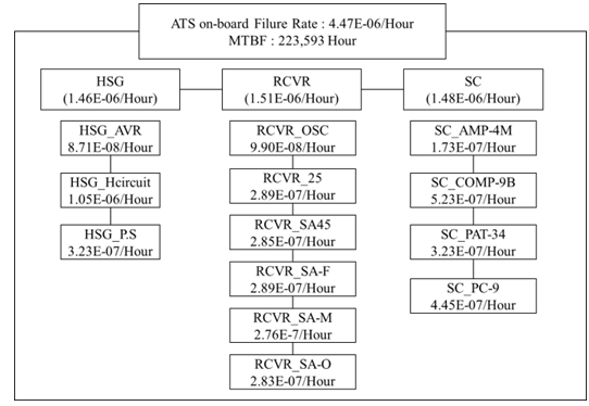 | Figure 3. Predicted MTBF RBD metrics for the ATS on-board device |
As shown in Figure 3, the results of our reliability predictions for the ATS on-board device suggest an average of 12 hours of use per day at 25℃, and 223,593 hours of use in the GB environment. This is equivalent to 25.5 years.
3.3. Calculating the Residual Lifespan
In accordance with the method proposed in section 2.3, we calculate the residual lifespan for the ATS on-board equipment. In equation (5), the shape parameter  depends on the failure type as listed in the 217 Plus data, reproduced in Table 1. The form of the Weibull function and the scale parameters
  for failures of the ATS on-board device are calculated by substituting the MTBF information from the ATS on-board device into equation (6), with results as shown in Table 4.
| Table 4. The shape and scale parameters from the Weibull function of the ATS on-board device, listed by failure cause |
| | Order | Cause of failure | | (hours) | | 1 | Part defect | 1.62 | 250,373 | | 2 | Manufacturing defect | 0.96 | 220,191 | | 3 | Design | 1.29 | 242,401 | | 4 | System management | 0.64 | 161,272 | | 5 | Wear-out | 1.68 | 251,100 | | 6 | Induced | 1.58 | 249,797 | | 7 | No defect | 1.92 | 252,772 | | 8 | Software | 0.70 | 177,141 |
|
|
In the equation for the residual lifespan function of the ATS on-board device, and
and  th ratio of Table 4. If applied to equation (5), the residual lifespan depends on the time. In other words, if is 219,000 hours (25 years) and if we use operating time up to the present for the ATS on-board device, we conclude that it takes 154,895 hours (or about 17.6 years) for the reliability to reach zero. If the failure rate function of the ATS on-board device using equation (7) is expressed through changes that depend on the time, we conclude that the failure rate slowly increases as shown in Figure 4.
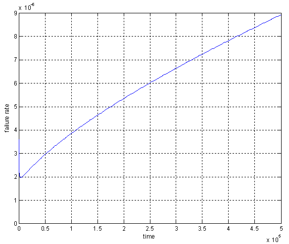 | Figure 4. Failure rate function for the ATS on-board device |
In this case, we conclude that the residual lifespan of the ATS on-board device, which is a predicted MTBF metric, has already exceeded the time of replacement. The equipment has been used for about 25 years consistent with the predicted reliability metric. When evaluated on the basis of the failure of similar equipment as provided by 217 Plus from the RAC, the amount of time it takes for the reliability to reach zero is still 154,895 hours (about 17.6 years). Therefore, no rapid change in failure rate is expected in Figure 4. We assume that no failure mode operation will be available.
3.4. Reliability Tests
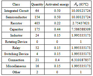
When we calculate the residual life of the ATS on-board devices, we conclude that the lifespan can be extended for a certain time period; in the future, this will let us confirm whether or not the equipment can operate without failure by using the reliability test[16].Table 5 shows the Telcodia standards as applied to the activation energy and acceleration factor for each part of the ATS on-board equipment consistent with equation (9).Table 5. The acceleration factors and activation energies for different parts of the ATS on-board device
 |
| |
|
By using the acceleration factor to calculate the activation energy for each part, an acceleration factor of 65℃ is calculated for the ATS on-board device. This temperature is applied only for those parts for which the activation energy is more than 0.4. Hence, we calculate an acceleration factor of 9.2199(indicating degradation stress). Through the use of equation (10), the test time with respect to the confidence level can be calculated as 1,306 hours at a confidence level of 60% and 1,715 hours at a 70% level. As previously mentioned, the reliability test for electronic components generally uses the 70% metric, and thus we also choose to use a confidence level of 70% in our reliability testing for the ATS on-board device.The reliability test data for the ATS on-board device suggests that if the EUTs, which have already been in operation for 25 years, are operated for 1,715 hours at 65℃ under continued normal operating conditions, failure-free operation should be possible for an additional 3 years at a 70% confidence level. We confirm that our test data shows no evidence of upcoming malfunctions, and the ATS on-board device can be used without any failure for the required lifespan extension. During the reliability test, the tester was installed so that the ATS wayside signal would be transmitted periodically and normal operation could be confirmed in each test, as shown in Figure 5.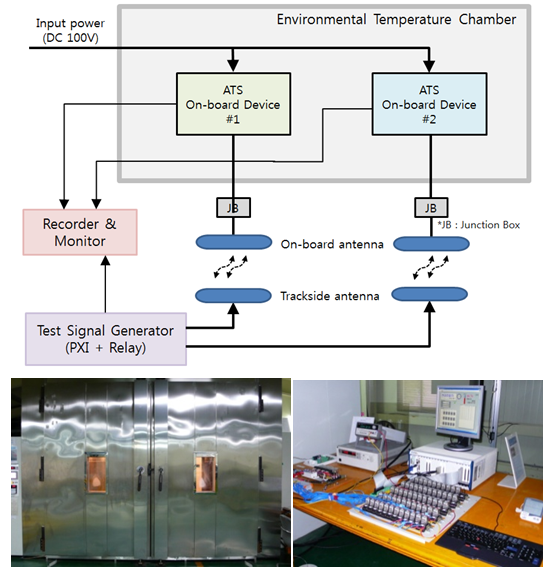 | Figure 5. Connection diagram and test pictures for reliability testing of ATS on-board device |
4. Conclusions
In this paper, we propose a method to predict the remaining operational life of obsolete equipment that is in long-term use when the reliability of signalling equipment has not been continuously monitored and in the absence of additional analytic information, notable information on failure rates for each part and data on failures that may have occurred during previous operations. For thisprocedure, we calculate the reliability for each part by using the MIL-HDBKstandard. We also calculate the residual lifespan by assuming that the calculated predicted lifespan will equal the designed lifespan. Next, to obtain the residual lifespan, we calculate the ratios for the types of failure of the signaling equipment and we use the parameter listed in 217F Plus. We estimate the remaining lifespan by using the calculated residual lifespan. Finally, to verify the confirmed remaining lifespan, we calculate the relevant parameter for the reliability test. Using this data, we develop the model that allows us to conduct a reliability test and associated evaluations. This model can be used to help to guide the future maintenance policies of railway operators that manage obsolete signalling equipment.
References
| [1] | Ju-Su Jang, etc, "A Study on Electronic Component Failure Rate Trend Based on Technology Changes", Proceedings of the KSR Annual Autumn Conference, pp2527-2538, 2011. |
| [2] | Park, Dae-Geun, etc, "Prediction of Future Lifetime Using Reliability Analysis Method about Rail Rubber Pad", Proceedings of the KSR Annual Autumn Conference, pp1964-1969, 2009. |
| [3] | MIL-HDBK-217F Notice-2, Department of Defense USA, 1992. |
| [4] | U.S. Department of Defense, MILITARY HANDBOOK Reliability Prediction of Electronic Equipment, 1991. |
| [5] | Hong YeonWoong, "Development of Failure Reporting Analysis and Corrective Action System", Proceeding of Korean Data And Information Science Society, Nov.17-18 pp97-112, 2006. |
| [6] | RiAC, Handbook of 217 Plus Reliability Prediction Models , 2006 |
| [7] | Lee Jae-Ho, etc , "A Study on the Reliability Demonstration of ATC and IXL for Korea High Speed Train", ICEE 2007 |
| [8] | Shin ducko, etc, "The Study on the verification of the reliability of Subsystem element of Train Control System in Korea High Speed Rail", Journal of Korean Society for Railroad, Vol. 9, Iss. 6, pp. 732-738, 2006. |
| [9] | Eduardo C. Moura, "A Method to Estimate the Acceleration Factor for Subassemblies", IEEE Transactions on Reliability, Vol.41, 1992. |
| [10] | Telcordia Special Report 332, Telcordia, 2000. |
| [11] | Jang Ju-Su, etc, "The Reliability Prediction : the application to the Bellcore standard of Samsung Electronics", Kyowoosa, pp.72-102, 2004. |
| [12] | JeongHae-Seong, etc, "The Reliability Analysis and the Application", YeongjiMunhwasa, ,pp.238-239, 2000. |
| [13] | Korea Electro technology Research Institute, "the Technical Committee of the electric field for the reliability improvement of components2006", 2006. |
| [14] | Korea Railroad Research Institute, "Reliability Diagnostics Review on ATS Onboard Equipment for Seoul Metro Line 2", 2008. |
| [15] | Relex7.7, MIL-HDBK-217 Equation References, 2005. |
| [16] | J.S. Jang, etc, "A Study of Optimal Burn-In Test Model for doing an Enhancement of System Reliability", Proceeding of the KSPE Annual Spring Conference, pp467-469, 2011. |
 Abstract
 Reference
 Full-Text PDF
 Full-Text HTML