-
Paper Information
- Next Paper
- Paper Submission
-
Journal Information
- About This Journal
- Editorial Board
- Current Issue
- Archive
- Author Guidelines
- Contact Us
Journal of Safety Engineering
2012; 1(2): 17-25
doi: 10.5923/j.safety.20120102.01
Textiles in Earth-Quake Resistant Constructions
 Abstract
 Reference
 Full-Text PDF
 Full-Text HTML
Subhankar Maity 1, Kunal Singha 1, Mrinal Singha 2
1Department of Textile Technology, Panipat Institute of Engineering & Technology, Harayana, India
2Department of Pharmaceutical Chemistry, CU Shah College of Pharmacy & Research, Gujarat, India
Correspondence to: Subhankar Maity , Department of Textile Technology, Panipat Institute of Engineering & Technology, Harayana, India.
| Email: |  |
Copyright © 2012 Scientific & Academic Publishing. All Rights Reserved.
The present paper reports some of the important developments in the field of application of textile materials in earthquake resistance constructions. Cement concrete reinforced with steel rods and rings are very popular in ordinary construction material. One major drawback of using steel is its susceptibility to environmental attack which can severely reduce the strength and life of concrete structures. Recent developments in the field of fiber reinforced cement (FRCs) composites have resulted in the development of highly efficient construction materials. The FRCs are unaffected by electro-mechanical deterioration and can resist corrosive effects of acids, alkalis, salts and similar aggregates under a wide range of temperatures. The fibers used in FRCs, their properties and their applications have been reported here. The various techniques of application of FRCs on the new and existing masonry structures to protect them from earthquake have been discussed here.
Keywords: Earthquake, Environmental attack, Fiber reinforced Cement, Electro-mechanical, Masonry Structure
Article Outline
1. Introduction
- Many un-reinforced wood and steel reinforced masonry structures are widely present around the world. These structures are designed for gravity loads and are not able to withstand seismic forces during earthquake and caused wide spread damages. To conserve the historic structural heritage of the country it is necessary to develop innovative techniques for rehabilitating deteriorating structures. After earthquake other than life concern, the removal and transportation of large amounts of concrete and masonry material causes concentrations of weight, dust, excessive noise, and requires long periods of time to gain strength before the building can be reopened for service[1-3].Repair of these structures with like materials is often difficult, expensive, hazardous and disruptive to the operations of the building. Most of these structures need strengthening or seismic upgrading work in order to ensure their conservation and functional use. Fiber Reinforced Cement (FRC) Composite materials, originally developed for the aerospace industry, are being considered for application to the repair of buildings due to their low-weight, ease of handling and quick implementation[2]. Review of literature indicates that numerous studies were conducted in the past to study the behavior of Fiber Reinforced Cement (FRC) Composite materials. Research and developments are going on to adapt these materials to the repair of buildings and civil structures. Appropriate configurations of fiber and polymer matrix are being developed to resist the complex and multi-directional stress fields present in building structural members. At the same time, the large volumes of material required for building repair and the low cost of the traditional building materials create a mandate for economy in the selection of FRC materials for .building repair.[1-6].
2. Structural Damages Due to Earthquake
- Earthquake is seismic vibration which generates ground motion both in horizontal and vertical directions. Due to the inertia of the structure this ground motion generates shear stress and bending moment in the structural framework. In earthquake resistant design it is important to ensure ductility in the structure, i.e. the structure should be able to deform without causing failure. Strength and ductility of structures depend mainly on proper detailing of the reinforcement in beam-column joints. The flow of forces within a beam- column joint may be interrupted if the shear strength of the joint is not adequately provided. Under seismic forces, the beam-column joint region is subjected to horizontal and vertical shear forces whose magnitudes are many times higher than those within the adjacent beams and columns. Conventional concrete looses its tensile resistance after the formation of multiple cracks. So, the joints need to be more ductile to efficiently bear or dissipate the seismic forces. Most failures in earthquake-affected structures are observed at the joint. A construction joint is placed in the column very close to the beam-column joint. This leads to shear or bending failure at or very close to the joint as shown in figure 1(a). The high compressive stress in concrete may also cause crushing of concrete as shown in figure 1(b). If the concrete lacks confinement the joint may disintegrate and the concrete may spall, shown in figure 1(c). All concrete structure create a hinge at the joint and more will be the number of hinge higher will be the probability of collapse. If the shear reinforcement in the beam is insufficient there may be diagonal cracks near the joints, shown in figure 1(d). This may also lead to failure of the joint. Again the high bending moment may cause yielding or buckling of the steel reinforcements as shown in figure 1(e).
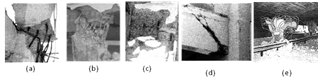 | Figure 1. (a) Failure at construction joint, (b) Crushing of concrete, (c) Spalling of concrete, (d) Diagonal shear crack, (e) Bending of steel[1] |
3. Fiber Reinforced Polymers and Composites
- Fiber Reinforced Cement (FRC) Composite materials are widely used in many structural applications where their mechanical performances are of primary importance. The stiffness and the strength of composites are dependent upon the mechanical properties of the constituents, but also upon the stress transfer processes occurring at the fiber/matrix interface[13]. Fiber Reinforced Cement (FRC) or Concrete composites are generally defined as composites with two main components, the fiber and the matrix as shown in figure 2[13-14].
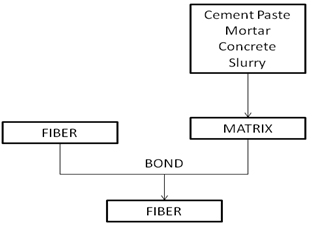 | Figure 2. Composite model considered as a two-component system, namely fiber and matrix |
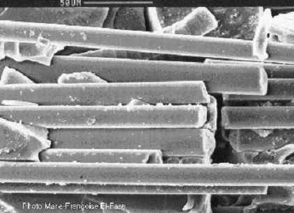 | Figure 3. Fiber Reinforced Concrete[13] |
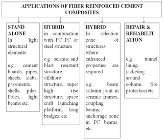 | Figure 4. Classes of applications of fiber reinforced cement composites[17] |
4. Materials for Strengthening of Structures
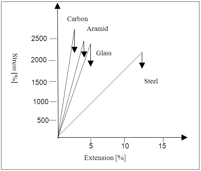
- Fiber reinforced cement composite is consist of high strength fibers embedded in a resin matrix. The fibers generally used in construction are Carbon (C FRCs), Glass (G FRCs) or Aramid (A FRCs). These fibers are sufficiently strong, even many times stronger than steel in the longitudinal direction but generally weak laterally. Typically these fibers show very less or no ductility. So the stress–strain behavior of most FRCs can be taken as linear elastic to failure. C FRC posses the highest Young’s modulus, generally around 150–200 GPa, with some Ultra High Modulus C FRCs being available with moduli up to 600 GPa. Strengths are generally in the range of 2500–3500 MPa. FRCs not only have the advantage of very high strength over conventional materials, but are also light weight and highly durable in many environments. The properties of fibers for FRCs have been shown in Figure 5.[14-21]
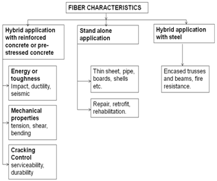 | Figure 5. Fiber Characteristics for FRCs[17] |
 | Figure 6. material for strengthening of concrete[23] |
5. FRC Plates as Reinforcement to Concrete Beams
- FRCs for strengthening of structures can be glued to an old and deteriorated concrete surface to improve its strength. This method is more convenient and durable than epoxy bonded steel plates. Meier (1987) has examined the suitability of carbon fiber reinforced epoxy laminates for rehabilitation of concrete bridges[22-23].The first repair work of a concrete bridge using CFC laminates has been carried out at Ibach Bridge, Lucerne, Switzerland. The 228 m long bridge was designed as a continuous beam of span 39 m several pre-stressing tendons of the bridge were accidentally severed preventing the bridge to operate at its full capacity. The bridge was repaired with a 2 mm thick 150 mm wide C FRC laminate. It was found that the repair work became particularly easy due to the use of composite materials. Owing to its light weight 175 kg steel could be replaced by only 6.2 kg of CFC. As a result the work could be carried out from a traveling hydraulic lift and the cost of scaffolding could be avoided. The composite is held in position by means of a vacuum bag, thereby avoiding pressers required in case of steel plates. Although CFC was 40 times more expensive than steel plates, it was estimated that the process saved 20% in cost[24-27].
6. FRCs as Wrapping on Concrete Elements
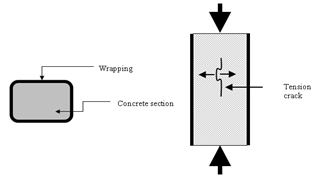
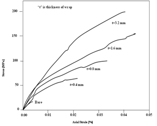
- The tensile strength of concrete is much less in comparison to its compressive strength As a result; even the compression members often fail due to the tensile stress that develops in the perpendicular direction of the compressive load as shown in figure 7. If such a concrete element is confined using a wrapping (figure 8), the failure due to tensile crack can be prevented. The compressive strength of the wrapped concrete element is several times higher than the unwrapped concrete element. Although this is known for a long time effective application of confinement could not be achieved due to a lack of suitable wrapping material. If the wrapping is torn the capacity of the element reduces dramatically. Therefore, the durability of the wrapping material is of utmost importance. In addition, the wrapping material remains exposed to environmental attack. Therefore, steel is unsuitable for this purpose. FRCs due to their non-corrosive nature offers an attractive alternative. Moreover, the light weight FRC fibers can be very easily wrapped around an old concrete column. However, typical stress-strain curve of cylindrical specimens wrapped with FRC of varying number of layers is presented in figure 9. It may be noted that with one layer of FRC wrap the ultimate strength of the specimens increased by a factor of 2.5. The ultimate strength went on to increase up to 8 times when 8 layers of the wrap were used.[24-25,28-32]
 | Figure 7. FRC Wrapping Around Concrete Elements[25] |
 | Figure 8. Wrapping of Column[41] |
 | Figure 9. Axial strength of circular columns with different levels of confinement[25] |
7. Glass Fiber Retrofitting to Protect Bridge from Earthquake
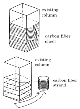
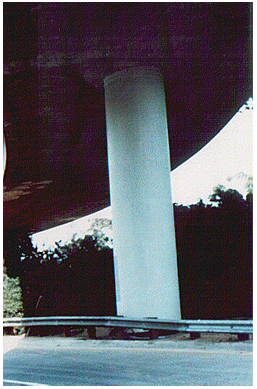
- Older concrete columns are reinforced with ring and rods of steel. These concrete columns crack and spall during seismic vibrations. They are also vulnerable to corrosion. Seismic upgrades have traditionally involved retrofits with concrete or steel jackets, but these techniques are expensive and time-consuming, and the jackets also require maintenance over time. An easier, more cost-effective technology for strengthening concrete columns has recently been developed, the Snap Tite Composite Column Reinforcement. Snap Tite consists of an external composite fiberglass jacket, approximately 1/8 inch thick, that literally “snaps on” to the concrete column as shown in figure 10. This composite is comprised of glass fibers and corrosion resistant isopolyester resins, manufactured into a single-seamed cylindrical jacket that encloses the column, which must be even and uniform in shape. The jacket contains the column, preventing the concrete from expanding due to seismic stress or temperature variations. Thousands of bridges columns in California are to be wrapped with jackets containing high performance glass fiber in order to protect the structure from severe earthquakes. The jacket are made from industrial glass fibers & isotophthalic polyester resin in contrast to the conventional sheet steel wraps and are designed to reduce the risk of serious seismic damage.[7,9,29,31-32,41].
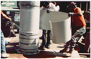 | Figure 10. Installing Prefabricated Fiberglass jacket[41] |
8. Snap Tite Technology for Column Reinforcement
- The Snap Tite Composite Column Reinforcement strengthens a concrete column by confining it in an external composite jacket, which prevents the concrete from expanding during seismic activity or prolonged freeze-thaw cycles. The pre-manufactured fiberglass jacket is comprised of glass fibers and corrosion resistant isopolyester resins. The resin completely encapsulates the reinforcing fiber network, which, for most applications, is conventional E-glass woven roving and bi-directional fabric. Each Snap Tite component is a single-seamed, cylindrical jacket that snaps on the column as shown in figure 11. The column is cleaned and prepared with a high performance urethane adhesive before the first jacket is applied. More jackets are applied until the desired thickness for the job is achieved. Adhesive is applied between layers, and the vertical and horizontal jacket seams are symmetrically alternated. A typical column will require 3 to 4 layers of jackets, with a nominal jacket thickness of around 1/8 inch thick. Each nested jacket is bound with belt clamps until the adhesive cures[7,9,14,41].
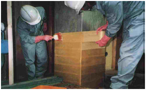
 | Figure 11. Snap tite applied beam surface[14] |
8.1. Benefits of snap tite
- Snap tite is recognized as one of the most cost effective and user friendly solutions for rehabilitating or upgrading existing steel reinforced concrete columns or structures. Snap Tite replaces steel, the conventional material used for column reinforcement, reducing installation and long-term maintenance costs. For example, Snap Tite, because of its light weight, can typically be installed in three hours vs. three days for steel, and can be lifted in place by workers using only a few pieces of light, mobile equipment. Snap Tite won't rust and never needs to be painted, even when installed in corrosive environments. The other market challenge to Snap Tite is the epoxy resin composite column wrap. Although this composite does meet performance requirements, it is much more expensive to manufacture. The current manufacturer of this resin also uses extensive equipment for installation, Snap Tite does not. Full-scale tests at two major universities have verified that columns reinforced with Snap Tite withstand three-to-eight times the deflection of columns without reinforcements. Preliminary tests indicate that Snap Tite can improve earthquake capability three times beyond that of a steel jacket. Snap tite jackets work by increasing the resistance to the phenomenon of spalling which occurs when an earthquake causes the concrete columns to shatter. This expose the steel reinforcement bars which then bend outward. The jacket also allow for greater deflection when a bridge column bends, so reducing the risk shear failure.[7-9,17,24-25].
9. Retrofitting Walls for Seismic Loads Using Aramid Fibers
- High strength fibers and elastometric polymer bonded to walls can significantly strengthen walls against wind, seismic and blast loads. This System uses woven aramid fiber sheets as the reinforcing material. Aramid fibers are arranged to the axial direction of the sheets as shown in figure 12. Aramid fiber sheets are characterized by light weight, high strength, no corrosion, and non-conductivity.
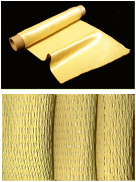 | Figure 12. Aramid fiber sheet[16] |
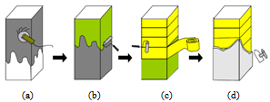 | Figure 13. Typical construction procedure: (a) Surface treatment, (b) Coating primer and epoxy resin, (c) Wrapping sheet and removing air with roller, (d) Coating epoxy resin |
 | Figure 14. Attachment of Kevlar Mat with Epoxy[25,41] |
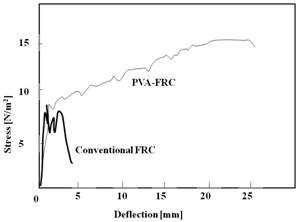 | Figure 15. High-flexural deformability of PVA-ECC[17] |
10. Developments in Fiber Reinforced Concrete for Earthquake Resistance
- Significant progress in research and development in fiber reinforced concrete has been seen. Generally, concrete is strong against compressive force, but weak against tensile force. As a result conventional concrete elements tend to suffer brittle shear failure. The beam columns joints are critical region for the seismic safety of buildings as discussed before. A new FRC has been developed with embedded polyvinyl alcohol (PVA) fiber in the matrix, which is called PVA-ECC[7]. It has been claimed that this concrete realized unprecedented ductility by way of optimization of matrix, fiber, and fiber/matrix interface through a micromechanical approach. Controlling the interaction between PVA fibers and calcium ions in the cement is important to obtaining the optimal frictional bond, which leads to excellent strain hardening behavior. The PVA-ECC has superior ductile property as compare to conventional FRCs as shown in figure 15, which makes it more suitable for creating earthquake proof buildings. The PVA-ECC wall itself absorbs energy from the earth quake and save buildings from seismic force. Again PVA offers cost effectiveness compared to other aramide and carbon fibers. And it has good workability as well[17, 33-39]
11. Base Isolation for Earthquake Resistance
- During earthquake the building which have fixed bases tends to displaced in opposite direction of the ground motion due to their inertia. So, the inertia forces acting on a building are the most important of all those generated during an earthquake. Figure 16 shows three different possible cases of deformation in the building frame whose bases are fixed. Due to these deformations the building may collapse during earthquake.
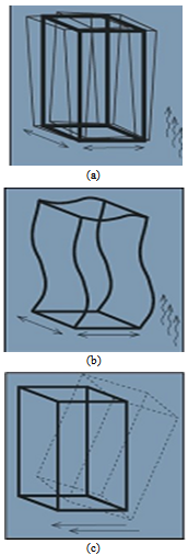 | Figure 16. (a) shock & vibration to a stiffened frame;(b) shock & vibration to a bolted frame: (c) shock & vibration to a unbolted frame.[40] |
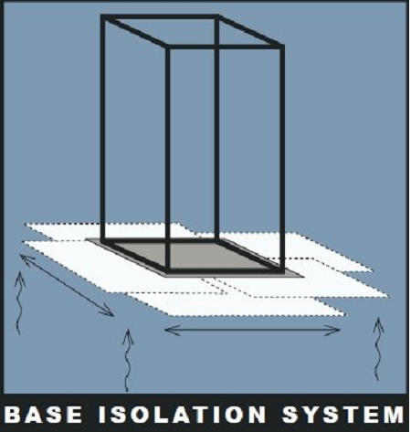 | Figure 17. Base isolation system[40] |
12. Conclusions
- Textile materials are successfully applied for earthquake resistant construction. The actual choice of fiber type, composite type, and number of layers of composite tiles for an earthquake resistance construction particular depends on the collaborative expertise of textile technologist and structural engineers. Fiber reinforced cement composites are found effective in construction and rehabilitation of masonry structures. Fibers used are high performance fibers such as aramid, carbon or glass. These fibers are judged more efficient than steel. Developments in resins are also going for getting long lusting effectively with performance. Various methodologies are also tried for applications of textile reinforced composited to strengthen the existing beams, columns and walls to protect them from seismic force. Base isolation method has been proposed for mitigating the effect of seismic shaking on low rise building.
References
| [1] | Mukherjee A., “Recent Advances in Repair and Rehabilitation of RCC Structures with Nonmetallic Fibers”, Indian Concrete Journal, 2002, Vol.76 (8), pp 496-502. |
| [2] | Altunişik A. C., “Comparison of earthquake behavior of reinforced concrete minarets using fiber-reinforced polymer composite”, The Structural Design of Tall and Special Buildings. doi: 10.1002/tal.731,2011. |
| [3] | Sharma K. H., Agrawal L. G., “Earthquake: Resistant Building Constructions”, ABD Pub, Second Edition, India, 2011. |
| [4] | Gernot Minke, “Construction manual for earthquake resistant house built of earth”, GATE-BASIN, GTZ-GmbH, Eschborn, Dec., 2001. |
| [5] | Balaguru P., Shah S.P., “Fiber Reinforced Cement Composites,” McGraw Hill, New York, 1992. |
| [6] | Bentur A., Mindess S., “Fiber Reinforced Cementitious Composites,” Elsevier Applied Science, London, UK, 1990. |
| [7] | “Glass fiber jackets to protect bridge from earth quake”, Technical Textile International, May, 1998. |
| [8] | Meier U., “Bridge Repair with High performance Composite Materials”, Materials und Technik, Vol 4, pp. 125-128, 1987. |
| [9] | “Glass Reinforced Plastic Bridge Opens”, Technical Textile International, July /Aug 1997. |
| [10] | Mirmiran A., Shahawy M., Samaan, M., “Strength and Ductility of Hybrid FRP-Concrete Beam-Columns”, ASCE J. Struct. Eng, vol. 25, no. 10, pp. 1085-1093, 1999. |
| [11] | Andres Lepage, Hooman Tavallali, Santiago Pujol, Jeffrey Rautenberg, “Towards Earthquake Resistant Concrete Structure with Ultra High-Strength Steel Reinforcement”, The 14th World Conference on Earthquake Engineering, Beijing, China October 12-17, 2008. |
| [12] | Kasal B. et al, “Seismic Performance of Laminated Timber Frames with Fibre-Reinforced Joints”, Earthquake Engg. Struct. Dyn., vol. 33, pp. 633-646, 2004. |
| [13] | Online Available:http://www.espci.fr/usr/chateau/COURS/Composites/Applet_comp. |
| [14] | Online Available:http://rebar.ecn.purdue.edu/ect/links/technologies/civil/snaptite.aspx |
| [15] | Mallick, P. K., “Fiber-Reinforced Composites: Materials, Manufacturing, and Design”, Marcel Dekker Inc., New York, 1993. |
| [16] | Dominguez, F.S., “Woven Fabric Prepregs,” Engineered Materials Handbook. American Society of Metals, Ohio, Vol. 1. 1987. |
| [17] | Henrik Stang, Victor C. Li, “Classification of Fiber Reinforced Cementitious Materials for Structural Applications”, 6th RILEM Symposium on fiber-Reinforced Concretes (FRC)-BEFIB, Italy, pp.197-218, 2004. |
| [18] | Tagawa Kikuko, “Positive reinforcement”, Industrial Fabric Product Review, pp. 20-27 May, 2001. |
| [19] | Victor C. Li, “Large volume, High Performance Applications of Fibers in Civil Engineering”, Journal of applied Polymer Science, Vol. 83, pp. 660-686, 2002. |
| [20] | Shrive N.G., “The use of fibre reinforced polymers to improve seismic resistance of masonry”, Construction and Building Materials, vol. 20, pp. 269–277, 2006. |
| [21] | Meier, “Proposal for a carbon fiber renforced composite bridgeaccross the strait of Gibratler at the narrowest site”, Proceedings Institute of Mechanical Engineers, Vol. 01, B2, 1986. |
| [22] | Shan Yao, Jiwen Jhang , Yongming Tu, “Application of engineered cementitious composite for earthquake resistance and disaster mitigation structure”, Advanced Materials Research, Vol: 168-170, pp. 1665-1669, 2011. |
| [23] | Victor C. Li, “Engineered Cementitious Composites for Structural Applications”, ASCE J. Materials in Civil Engineering, Vol. 10, No. 2, pp. 66-69, 1998. |
| [24] | Priestley M. J. N., Seible F., Calvi, G. M., "Seismic Design and Retrofit of Bridges" John Wiley & Sons, pp. 686, 1996. |
| [25] | Reza M. Esfahani, “Axial Compressive Strength of Reinforced concrete columns Wrapped with FRP”, 1st Conference on Application of FRP Composites in Construction & Rehabilitation of Structure, Tehran, Iran, May, 2004. |
| [26] | Koseki J., Tateyama M., Watanabe K., Nakajima S., “Stability of earth structures against high seismic loads”, Keynote lecture, Proc. 13th Asian Regional Conference on Soil Mechanics and Geotechnical Engineering, Vol.2, 2007. |
| [27] | An W., Saadatmanesh H., Ehsani M. R., “R/C Beam Strengthen with ERP Plates: Analysis and Parametric Study”, Journal of Structural Engineering, ASCE, Vol. 117, no. 11, pp. 3434-3455, 1991. |
| [28] | Tatsuoka F., Koseki J., Tateyama M., “Performance of Earth Reinforcement Structures during the Great Hanshin Earthquake“, Special Lecture, Proc. Int. Sym. On Earth Reinforcement, IS Kyushu '96, Balkema, vol. 2, pp. 973-1008, 1997. |
| [29] | Wehbe N. I., Saiidi M. S., Sanders D. H., “Effects of Confinement and Flares on the Seismic Performance of Reinforced Concrete Bridge Columns”, Report No. 97-2, CCEER. Department of Civil Engineering, University of Nevada, Reno, September 1997. |
| [30] | Galunic B., Bertero V. V., Popov E. P., “An Approach for Improving Seismic Behavior of Reinforced Concrete Interior Joints”, Report No. UCB/EERC-77/30, University of California, Berkeley, 1977. |
| [31] | Kono S., Inazumi M., Kaku T., “Evaluation of Confining Effects of CFRP Sheets on Reinforced Concrete Members”, Proc. Second Int. Conf. on Composites in Infrastructure, Department of Civil Engr. and Engr. Mech., Univ. of Arizona, Tucson, Arizona, PP. 343-355, 1998. |
| [32] | Mander J. B., Priestley M. J. N., Park, R., (1988). “Theoretical Stress-Strain Model for Confined Concrete Columns”, ASCE Journal of Structural Engineering, vol. 114, no. 8, pp. 1804-1826, 1988. |
| [33] | Kanda T., Watanabe S., Li V. C., “Application of Pseudo Strain-Hardening Cementitious Composites to Shear Resistant Structural Elements,” To appear in Proc. Fracture Mechanics of Concrete Structures - 3, AEDIFICATIO Publishers, Freiburg, Germany, Oct., 1998. |
| [34] | Li V. C., “Damage Tolerance Of Engineered Cementitious Composites,” Advances in Fracture Research Proc., 9th ICF Conference on Fracture, Sydney, Australia, pp. 619-630, 1997. |
| [35] | Mohammad R. Ehsani, Eeri M., Saadatmanesh H., “Fiber Composites: An Economical Alternative for Retrofitting Earthquake Damaged Precast Concrete Wall”, Earthquake Spectra, Vol. 13, No. 2, May, 1997. |
| [36] | Naaman, A.E., Reinhardt, H.W., Co-Editors, "High Performance Fiber Reinforced Cement Composites: HPFRCC 2, RILEM, No. 31, E. & FN Spon, London, 1996. |
| [37] | Reinhardt, H.W., Naaman, A.E., Editors, "High Performance Fiber Reinforced Cement Composites," RILEM, Vol. 15, E. & FN Spon, London, 1992. |
| [38] | Drdacky M., Lesak J. Avramidou N. “Behaviour of masonry walls strengthened against seismic effects by yarn composite strips or geo-nets mounted on their surface”, 1st International Conference on Vulnerability of 20th Century Heritage to Hazards and Prevention Measures, CICOP, Rhodes, April, vol. 3-5, 2002. |
| [39] | Ganesan N., Indira P.V., Ruby Abraham, “ Steel Fiber Reinforced High Performance Concrete Beam-Column Joints Subjected to Cyclick Loading”, ISET Journal of Earthquake Technology, Technical Note, Vol. 44, No. 3-4, pp. 445–456, Sept.-Dec. 2007. |
| [40] | Online Available: www.architectjaved.com/ earthquake resistant structures/base isolation techniques for earthquake resistance. |
| [41] | Toshimi Kabeyasawa, “Recent Development of Seismic Retrofit Methods in Japan”, Japan Building Disaster Prevention Association, January, 2005. |