-
Paper Information
- Paper Submission
-
Journal Information
- About This Journal
- Editorial Board
- Current Issue
- Archive
- Author Guidelines
- Contact Us
International Journal of Optics and Applications
p-ISSN: 2168-5053 e-ISSN: 2168-5061
2025; 10(1): 1-8
doi:10.5923/j.optics.20251001.01
Received: Jun. 15, 2025; Accepted: Jul. 12, 2025; Published: Aug. 8, 2025

Tunable-Focus Coaxial Imaging Design for Laser Processing Monitoring under Chromatic and Mechanical Deviations
 Abstract
 Reference
 Full-Text PDF
 Full-text HTML
Chia-Yu Hu, Ping-Hang Wu
Industrial Technology Research Institute, Department of Intelligent Photonic Manufacturing System, No. 8, Gongyan Rd., Liujia Dist., Tainan City, Taiwan (R.O.C)
Correspondence to: Chia-Yu Hu, Industrial Technology Research Institute, Department of Intelligent Photonic Manufacturing System, No. 8, Gongyan Rd., Liujia Dist., Tainan City, Taiwan (R.O.C).
| Email: |  |
Copyright © 2025 The Author(s). Published by Scientific & Academic Publishing.
This work is licensed under the Creative Commons Attribution International License (CC BY).
http://creativecommons.org/licenses/by/4.0/

Coaxial optical monitoring of laser material processing surfaces is a growing trend to enable intelligent assistance functions in manufacturing systems. This work proposes a novel coaxial optical monitoring system that integrates an afocal Galilean lens attachment with axial motion of the concave element to actively tune the image plane. Unlike conventional static optical systems, this design simultaneously compensates for both chromatic focal shifts—caused by mismatched illumination and laser wavelengths and mechanical positioning errors that affect the working distance. Furthermore, by incorporating a rotating polarization beam splitter within a compact coaxial module, our system achieves stable, high-contrast imaging across a broad spectral range. Most importantly, this coaxial tube lens design achieves these functions with significantly reduced complexity and cost. It is particularly well-suited for flexible laboratory environments requiring rapid adaptation to varying laser wavelengths and working distances, while preserving visible-light monitoring capability. Overall, the proposed design improves both the adaptability and reliability of vision systems in laser processing applications.
Keywords: Image plane shifts, Afocal Galilean attachment lens, Coaxial vision
Cite this paper: Chia-Yu Hu, Ping-Hang Wu, Tunable-Focus Coaxial Imaging Design for Laser Processing Monitoring under Chromatic and Mechanical Deviations, International Journal of Optics and Applications, Vol. 10 No. 1, 2025, pp. 1-8. doi: 10.5923/j.optics.20251001.01.
Article Outline
1. Introduction
- The smart manufacturing attracts increased interest in laser micromachine, enabling welding [1,2], cutting [3], and surface modification [4-6] across various industries. To further enhance process quality and achieve intelligent automation, on-line optical monitoring of laser processing surfaces has attracted significant attention [1,7-9]. An effective approach involves utilizing a coaxial vision system [2-7,10], in which the monitoring optical axis is aligned with the laser beam path to ensure accurate and consistent observation of the processing area. Achieving high-contrast images is essential for accurate data interpretation in vision-based monitoring systems. However, image quality in vision-based monitoring systems is compromised by several factors. For examples, the Thombansen’s work [11] demonstrates that coaxial camera images using LED illumination exhibit limited image quality compared to those using VCSELs and laser diodes. It also highlights that illumination systems perform best when their wavelength matches the laser processing wavelength. Cheol-Hee Kim [2] shows images obtained through various illumination condition and suggest 810nm illumination is better than 532 and 660nm illumination condition. Based on our understanding, this is due to the fact that the laser processing and illumination sources in the vision optics operate at different wavelengths. As a result, their light rays passing through the same processing lens but produced different working distances. Other studies have employed near-infrared cameras for monitoring, as their operating wavelengths closely match the laser processing wavelength [6]. Moreover, laser positioning defocus errors can arise from mechanical inaccuracies during the assembly of the optical system [12]. Binh’s group develop dynamic focus tuning to correct focus position errors caused by mechanical inaccuracies in optical systems [13].Achieving high-contrast images is essential for accurate data analysis; however, image quality in vision-based monitoring systems is degraded due to two factors. The first is variation in working distance induced by inevitable mechanical assembly inaccuracies and cause deviations in the working distance. Vision system quality can be affected by mechanical error resulting in skewing of the optical working distance from the designed values. The second arises from the mismatch between the illumination wavelength used for monitoring and the laser processing wavelength, leading to focal plane shifts and image defocus. Conventional laser processing F-theta scanning lenses are typically optimized for single-wavelength operation and do not accommodate such multi-wavelength or mechanical variations. The achromatic objective lenses commonly used in laser micromachining are not suitable for resolving defocusing issues, as residual micro defocus still appears on the working plane. While achromatic lenses can correct for chromatic aberration, due to their adhesive bonding, cemented achromatic lenses lack sufficient thermal tolerance for high energy laser processing. For vision optics, the function of commercial zoom lenses [14] allows adjusting magnification or field of view (FOV) under the same working distances but are not designed for correcting working distances offset. Alternatively, such systems are often complex and designed for specific telescope [15] or microscopy configurations, which limits their practicality for monitoring in rapid laboratory laser processing testing platform. Although prior studies have explored afocal Galilean attachment lens groups [16-18] and three-lens configurations for focus adjustment [19], their application scenarios remain limited or insufficiently addressed. In contrast, this study presents a novel application of an afocal Galilean attachment lens group that compensates for image plane deviations by utilizing the axial motion of a concave lens. This design effectively addresses issues such as mechanical assembly errors, which can cause misalignment between the laser processing focus plane and the vision system’s imaging plane.The improvement in image quality is achieved by precisely aligning the working distances of the laser processing beam and the vision system to coincide at the same focal plane. The optical system is based on a non-complex four-lens configuration, derived from a three-lens afocal Galilean attachment, utilizing the axial displacement of a single concave lens to superimpose images formed by different wavelengths onto the same image plane. For example, illumination at 632 nm and a laser source at 1550 nm can be focused to exactly matching working distances, effectively solving defocus issues caused by chromatic and mechanical factors. As a result, images of the laser processing working plane remain clear under illumination at various wavelengths.The optical design was experimentally validated using a ring-shaped illuminator. The validation process involved two key steps: first, calculating object distances to simulate the focusing behavior of both infrared and visible light; second, improving image performance by adjusting the axial position of the concave lens within the Galilean attachment to bring different wavelengths into focus on the same image plane. During the development of this compact coaxial optical vision module, image contrast varies with the rotation angle of the wire-grid polarization beam splitter was observed. This concept offers significant advantages in vision-based optical systems where image contrast degrades due to working distance shifts caused by chromatic dispersion or mechanical misalignment. Conventional achromatic lenses and commercial zoom optics lack the flexibility to correct for these variations, especially in flexible laboratory testing environments that require rapid adaptation to diverse laser processing wavelengths while maintaining visible-light monitoring capability.
2. Optical Design and Considerations
- The proposed optical design system aims to address working distance offsets. It consists of three main components: imaging, focusing, and an afocal Galilean attachment lens group [18]. This section provides a detailed description of the design process, system parameters, and working distance deviations.
2.1. Explanations of Working Distance Differences
- Figure 1 shows the schematic diagram of working distances offset of processing lens and vision optics. The narrower blue color line represents laser-processing beam and gray wider line represents coaxial optical paths. (a) Before modifying focusing offset for mechanical inaccuracies during assembly, as well as the focusing offset between the monitoring and processing beams (b) the proposed method is to tune working distances by moving lens in designed coaxial optical system. The monitoring light and processing light have the same image planes. For example, the working distances of F-theta lens with focal length of 420mm, laser process wavelength 1.064 μm and illumination source with spectrum of 0.66 μm are 499.2 mm and 488 mm. The offset of working difference is 11mm which leads to blurred images of monitoring captured images. Modifying the working distances of vision optics is essential for improving real-time monitoring images during laser processing. It is necessary to adjust the working distances not only for the imaging optics, but also for both the illumination and the processing laser, ensuring proper alignment and focus. Additionally, such adjustments can help compensate for mechanical misalignments in the system.
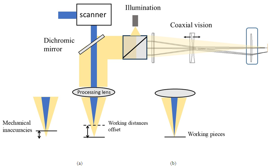 | Figure 1. Shows the schematic diagram of working distances offset of processing lens and vision optics. The narrower line with blue color represents laser-processing beam and gray wider line represents coaxial optical paths. (a) Before modifying focusing offset (b)after modifying working distances |
2.2. Design Specification
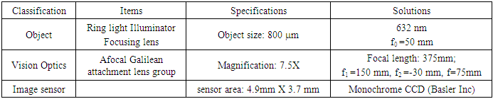
- The vision optical model is non-complex and allows magnification adjusting by only substituting imaging lens. The focusing lens is the laser processing lens in front of the afocal attachment lens for focusing the observed objects, while the imaging lens is the third lens in front of the image sensor, such as a charged coupled detector (CCD) or photodiodes. The symbol f represents the focal length of the focusing lens, while f1 represents the focal length of the convex lens, and f2 represents the focal length of the concave lens in an afocal Galilean lens group. The imaging convex lens and has focal length fi. D represents the distance between the imaging lens and the image sensor surface. The required size of an image is relative to the size of the object based on application. The ratio of the image size to object size determines the magnification of the vision optics. The focal length of the vision optics (F) is obtained from multiplying the ratio of the afocal attachment lens system (f1/f2) by the focal length of imaging lens (fi),
 . The axial motion of the concave lens allows tunable image positions which focus the rays with different wavelengths or different object distances reflected from the observed object exactly on the same image plane position. If the magnification of the vision optics needs to be changed, focal length of imaging lens is adjusted without changing the design of afocal attachment lens group. The afocal attachment lens group comprises three optical components (convex, concave, convex): a convex lens with a focal length of 150 mm (49362, Edmund Optics.), a concave lens with a focal length of -30 mm (48351, Edmund Optics.), and then another convex lens with a focal length of 75mm (89433, Edmund Optics.). The processing (focusing) lens is with 50 mm focal length (17421, Edmund Optics) for simulating focusing on workpiece. The design specifications, including the field of view (FOV), magnification, focal lengths, spectral range, illuminator and sensor parameters are shown in Table 1. In this case, the vision optics has the focal length of 375mm and magnification 7.5X which produces an image of the object on the full sensor area.
|
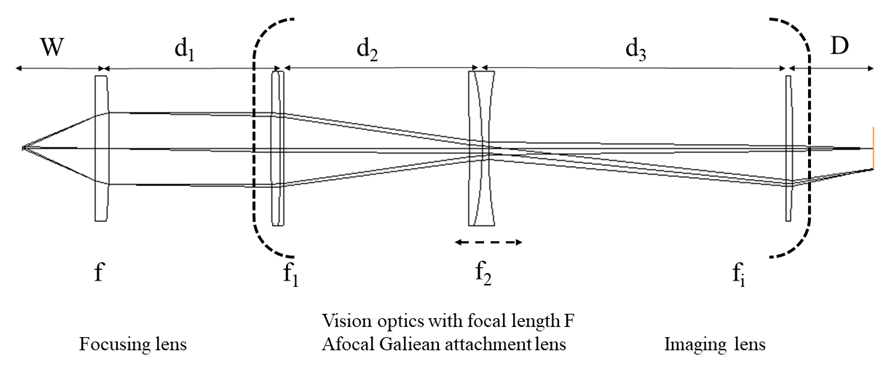 | Figure 2. Diagram of the vision optical system comprising the afocal Galilean attachment lens group and focusing lens. The concave lens (f₂) is axially adjustable for image tuning |
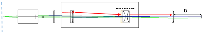
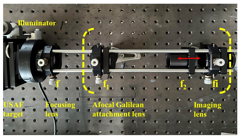 | Figure 3. Experimental setup of optical system. Vision optics are marked in dashed bracket. The optical elements and parameters correspond to description in section 2 |
3. Results and Discussion
3.1. Demonstration Focusing Tuning System
- Figure 4 presents three optical configurations that demonstrate image plane shifts caused by wavelength-dependent behavior. In these diagrams, the red dashed rays represent 632 nm (visible red light), and the black rays represent 1550 nm (near-infrared). Case (a) illustrates geometric chromatic effect, where different wavelengths focus at distinct axial positions due to dispersion. Case (b) shows that, at a fixed object distance, the two wavelengths experience different refraction angles, leading to spatial separation of image planes. Case (c) achieves equal refraction angles for both wavelengths by adjusting the object distance, thereby aligning their image planes. This third configuration forms the basis for a tunable image plane design, as equal refraction angles imply identical incident angles on the first lens of the vision optics, resulting in coincident focal positions. To experimentally validate this tunable imaging concept, the object distance was varied to simulate working distance deviations. The concave lens in the afocal attachment was then axially adjusted to restore image sharpness. When the system is optimized for 1550 nm at a working distance of 45.17 mm, image degradation occurs at 632 nm due to the difference in exit ray angles (3.4° vs. 2.5°). Shifting the object to 47.6 mm leads to visible blur at 632 nm, confirming the chromatic focal offset. By axially translating the concave lens toward the focusing element, image clarity was restored. While this compensation mechanism effectively corrects focal shifts, it also introduces minor magnification variation reducing the number of resolvable line pairs in the field of view from nine to eight. Additional experiments confirmed that intentional mechanical misalignment (e.g., object distance offset) can be compensated by concave lens adjustment, as demonstrated in Figure 5(d–f).
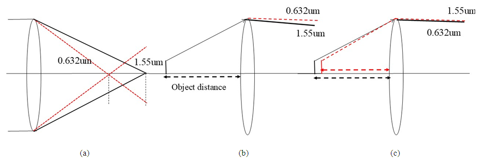 | Figure 4. Three scenarios of image plane shift: (a) Geometrical chromatic aberration, (b) Refraction difference at fixed object distance, and (c) Different object distances yielding the same refraction angle. The red and black dashed lines represent red and infrared light, respectively |
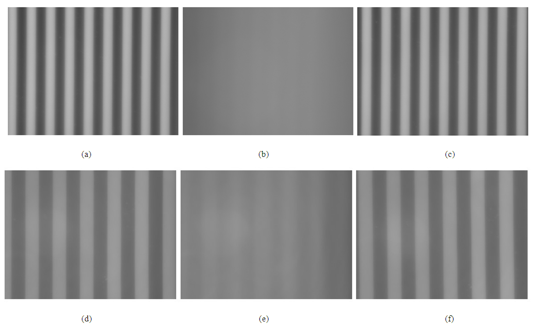 | Figure 5. Images of a line grating target with a resolution of 15 lp/mm: (a) At 1550 nm, optimal focus is achieved at an object distance of 45.17 mm. (b) Displacing the target by 2.4 mm away from the focusing lens results in a blurred image. (c) Axial movement of the concave lens in the attachment group toward the focusing lens restores image clarity |
3.2. Compact Coaxial Vision Module Embedded in Equipment
- Figure 6 shows a compact vision optics module designed for integration with laser processing machines. The system consists of an afocal attachment lens, a focusing lens, and a wire-grid polarization beam splitter. The red line denotes the optical axis, while the yellow path indicates the coaxial illumination from an LED spot light source with a 6 mm emission radius. Image performance at various object distances is characterized in Appendix A1. Image blur caused by object displacement can be mitigated by axially adjusting the concave lens within the afocal attachment. An interesting observation is that image contrast varies as the wire-grid polarization beam splitter is rotated about the optical axis. The contrast reaches its peak at a specific rotation angle, as indicated by the dashed line in Figure 6. This angular dependence is further illustrated in Video 1 (Appendix A3). The observed contrast variation is partly attributed to polarization effects induced by the surface properties of the target object [20].
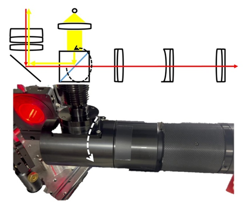 | Figure 6. A complete coaxial vision optics module with polarization beam splitter |
4. Conclusions
- Applying axial motion to the second concave lens in an attached afocal Galilean lens group provides a tunable image plane position, allowing rays of different wavelengths to be precisely focused on the same image plane. This optical design is suitable for vision optics applications where cemented achromatic lenses are unsuitable for laser processing, and where commercial zoom lenses are impractical for vision monitoring in rapid testing environments. The system also mitigates blurred images caused by environmental factors or mechanical assembly errors. The focusing lens can be an objective lens, F-theta lens, projection lens, or other types as required. Optical magnification is adjusted via the imaging lens in an afocal Galilean lens group without modifying the concave or convex lenses. Blurred focus resulting from working distance shifts can be corrected by axially adjusting a single concave lens within the Galilean lens group to shift the image plane position. Additionally, rotating the wire-grid polarization beam splitter allows optimization of image contrast by controlling polarization effects. Finally, the optimal image quality is achieved. This design approach is both effective and straightforward, making it well-suited for vision optics in laser processing platforms that require adaptability to a wide range of testing samples.
Appendix A: Configuration Details
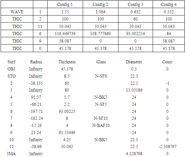
- A 1 Lens Data, optical system layout, Configuration table in design process
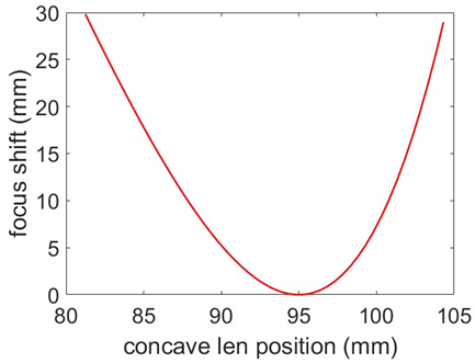
 A 2 The relationship between the concave movement distance and focus offsetRay Transfer Matrix (ABCD matrix method)
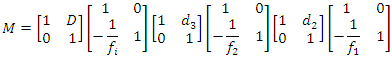
 A 3 The imaging contrast varies with the rotation angle of the wire-grid polarization beam splitter. Maximum contrast is achieved by optimizing the splitter’s orientation.
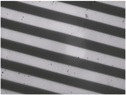 Video 1 Contrast varies with wire grid polarization beam splitter