-
Paper Information
- Paper Submission
-
Journal Information
- About This Journal
- Editorial Board
- Current Issue
- Archive
- Author Guidelines
- Contact Us
International Journal of Optics and Applications
p-ISSN: 2168-5053 e-ISSN: 2168-5061
2019; 8(1): 1-7
doi:10.5923/j.optics.20190801.01

Designs of One-Element Refracting System for Gaussian and Annular-Gaussian Beams Transformations
 Abstract
 Reference
 Full-Text PDF
 Full-text HTML
Abdallah K. Cherri, Nabil I. Khachab, Mahmoud K. Habib
Kuwait University, College of Engineering and Petroleum, Electrical Engineering Department, Safat, Kuwait
Correspondence to: Abdallah K. Cherri, Kuwait University, College of Engineering and Petroleum, Electrical Engineering Department, Safat, Kuwait.
| Email: |  |
Copyright © 2019 The Author(s). Published by Scientific & Academic Publishing.
This work is licensed under the Creative Commons Attribution International License (CC BY).
http://creativecommons.org/licenses/by/4.0/

In this paper, the design of one-lens (instead of two-lens) refracting system is proposed to provide particular laser irradiance profiles. Specifically, the one-lens surfaces are derived for three types of laser beam transformations: (i) Gaussian to Annular-uniform; (ii) Annular-Gaussian to Annular-uniform; and (iii) Annular-Gaussian to Gaussian. It will be demonstrated that the one-element designs outperform the two-element ones (for the same system parameters previously reported) for these beams regarding the system length. In particular, the system length is reduced by almost 39% for both the Gaussian and Annular-Gaussian to Annular-uniform beam transformation for the same starting refraction angle. For the beam transformation of Annular-Gaussian to Gaussian beam transformation, this system length is reduced by almost 34% with slightly larger initial refraction angle.
Keywords: Beam Shaping, Refracting system, One-lens design
Cite this paper: Abdallah K. Cherri, Nabil I. Khachab, Mahmoud K. Habib, Designs of One-Element Refracting System for Gaussian and Annular-Gaussian Beams Transformations, International Journal of Optics and Applications, Vol. 8 No. 1, 2019, pp. 1-7. doi: 10.5923/j.optics.20190801.01.
Article Outline
1. Introduction
- Gaussian or near-Gaussian laser beams are heavily used in many applications in which the laser beam is being focused to a small spot [1]. However, in many other industrial, military, medical applications laser beams with uniform intensity profiles are needed to illuminate evenly an entire processed area such as in coherent optical image processing, optical pattern recognition, Fourier transform-based correlation, and materials processing tasks [2-8]. In this regard, beam shaping techniques were proposed to do the conversion of Gaussian and non-Gaussian laser beams to uniform and other beams profiles. Refractive optical system technique is among many successful and efficient methods that can achieve this conversion [9-14]. This technique relies on geometric optics for designing laser beam shapers. The designed optical element functions as a field mapping of the input beam distribution to provide a desired output beam profile. Over the years, single-element and two-element refracting systems have been proposed to achieve beam shapers [15-20]. In this work, one-element refracting beam shaping systems are designed instead of two-element systems that were recently reported in [21]. The mathematical expressions of the input and output lens surfaces are derived for the following beams transformations: (i) Gaussian to Annular-uniform; (ii) Annular-Gaussian to Annular-uniform; and (iii) Annular-Gaussian to Gaussian. It will be demonstrated that the one-element designs achieve smaller system length, compared to the two-element refracting systems previously reported for the same system parameters.
2. Design Considerations
- As stated in [9], two main conditions govern the refracting optical system for beam shaping: 1. The geometrical optics intensity law, i.e., the ratio of the input beam power to the output beam power must equal to a constant.2. The optical path length, i.e., all input rays that enter and leave the lens must travel the same optical path length.In addition, one can add a third condition which is related to geometrical optics rays tracing, i.e.:3. All input rays that enter and leave the lens must be parallel to each other’s.A geometrical configuration of half of the proposed axially-symmetric refracting system is shown in Figure 1 for Gaussian to annular-uniform beam transformation. Note that with some minor modifications, the set-up in Figure 1 can also be used for other beam shapers.
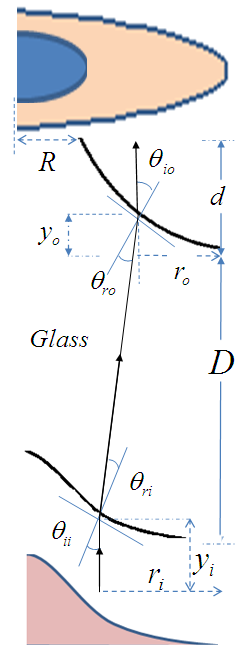 | Figure 1. The geometric set-up of the one-element refraction system beam transformation |
 | (1) |
 | (2) |
 From the geometry of the set-up in Figure 1, one can deduce that:
 | (3) |
 and use Eq. (3), we obtain:
 | (4) |
 | (5) |
 | (6) |
 of the surfaces need to be large.
  | (7) |
3. Laser Beam Transformations
- The above-mentioned design procedure will be applied in this section to transform three types of beams.
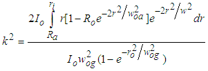
3.1. Gaussian to Annular-Uniform Beam Transformation
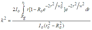
- As shown in Figure 1, an input Gaussian beam will be redistributed by the designed lens surfaces to form an output annular-uniform beam. The law of intensities implies that the ratio k2 between the two cross-sectional areas is given by:
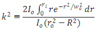 | (8) |
 | (9a) |
 | (9b) |
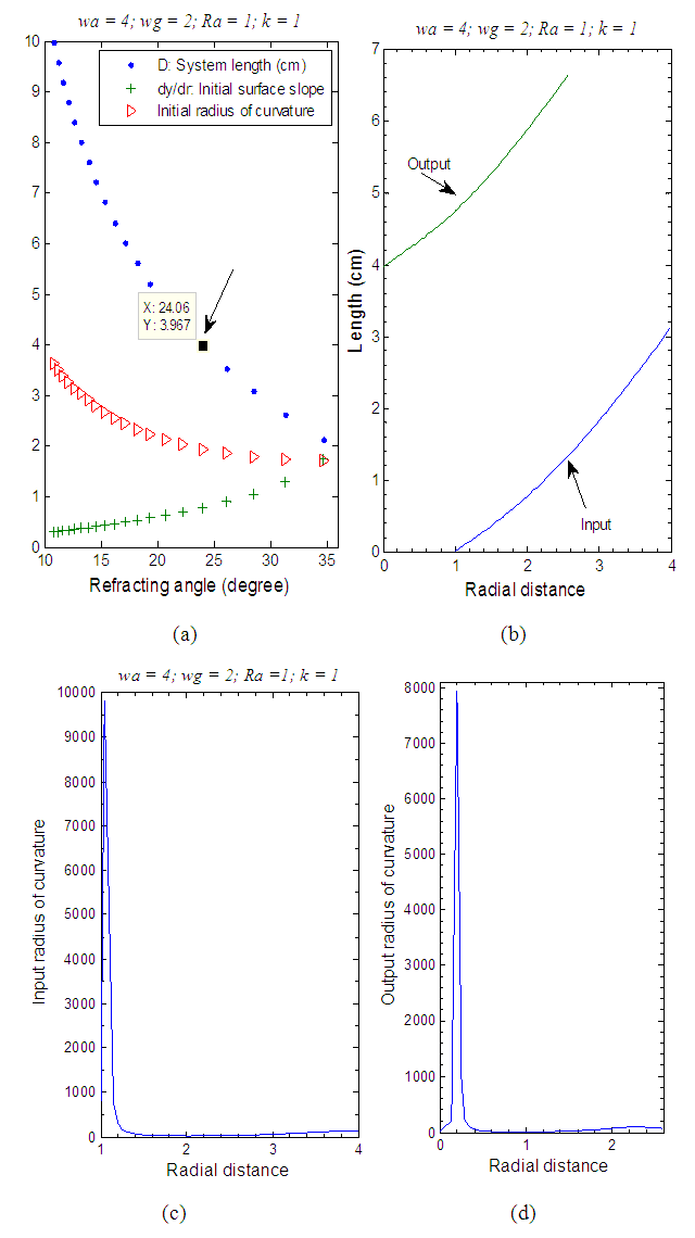
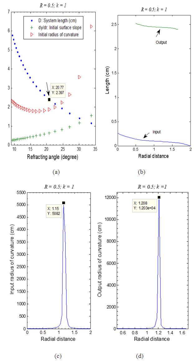 | Figure 2. Gaussian to Annular-uniform design: (a) effect of the refracting angle on the system length; (b) the input and the output surfaces yi(ri) and yo(ro); (c) and (d) the radii of curvature of the surfaces |
 | (10a) |
 | (10b) |
 | (11a) |
 | (11b) |
3.2. Annular-Gaussian to Annular-Uniform Beam Transformation
- The refracting one-lens design process can be applied to transform annular-Gaussian to annular-uniform beams. In this case, the cross-sectional areas ratio for the two beams is given by:
 | (12) |
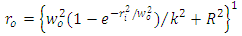
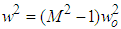 is the beam spot size in the large Fresnel number limit; is the magnification; Ro is the reflectivity of the central mirror [1]. The output radius ro is obtained from Eq. (12) as:
 | (13) |
 , Eq. (13) is simplified to:
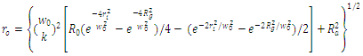 | (14) |
 | (15a) |
 | (15b) |
 | (16a) |
 | (16a) |
 | Figure 3. Annular-Gaussian to Annular-uniform design: (a) choosing the system length for a specific refracting angle; (b) the input and the output surfaces; and (c) the input and the output radii of curvatures |
3.3. Annular-Gaussian to Gaussian Beam Transformation
- For this type of beam shaping, the cross-sectional areas ratio for the two beams is written as:
 | (17) |
 is the beam spot size in the large Fresnel number limit; is the magnification; Ro is the reflectivity of the central mirror [1]. Note that
  when
when  . From Eq. (17) we can obtain the output radius of the Gaussian beam as:
 | (18) |
 | (19a) |
 | (19b) |
 | (20a) |
 | (20b) |
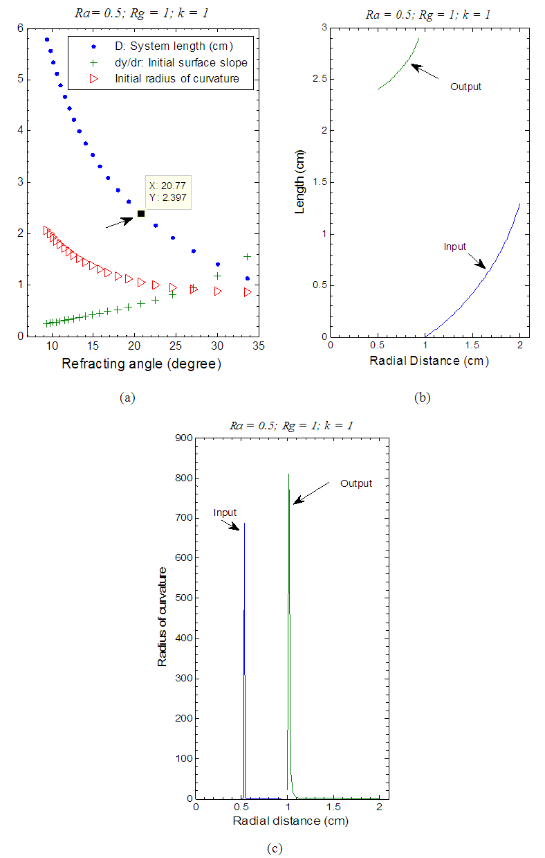
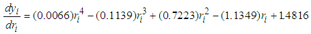
 | Figure 4. Annular-Gaussian to Gaussian design for the same D used in [21], but with a smaller θri: (a) choosing the system length for a specific initial refracting angle; (b) the input and the output surfaces; and (c) the input and the output radius of curvature of the surfaces |
 | (21a) |
 | (21b) |
 | (22a) |
 | (22b) |
 | Figure 5. An alternative design for Annular-Gaussian to Gaussian transformation with D = 2.987 cm, θri = 29.16o: (a) choosing the system length for a specific initial refracting angle; (b) the input and the output surfaces; and (c) the input and the output radius of curvature of the surfaces |
4. Conclusions
- One-element lens designs for transforming laser beam profiles are considered in this work using optical refracting system. The lens-design is applied to three types of beam transformations, (i) Gaussian to Annular-uniform; (ii) Annular-Gaussian to Annular-uniform; and (iii) Annular-Gaussian to Gaussian. The mathematical expressions for the aspheric surfaces are derived for the three types of laser beams. In addition, few important parameters such as the length of the set-up, the radii of curvature of the surfaces, and the initial refracting angle for annular beam were discussed. These designs are compared to the two-element refracting systems previously reported in [21]. It was demonstrated that the one-element designs outperform the two-element ones regarding the system length D and the initial refracting angles for annular beams at the price of having smaller values for the surfaces radii of curvatures.