-
Paper Information
- Previous Paper
- Paper Submission
-
Journal Information
- About This Journal
- Editorial Board
- Current Issue
- Archive
- Author Guidelines
- Contact Us
International Journal of Optics and Applications
p-ISSN: 2168-5053 e-ISSN: 2168-5061
2017; 7(2): 42-48
doi:10.5923/j.optics.20170702.03

Analytical Investigation of Slow Light Systems with Strained Quantum Wells Structure under Applied Magnetic and Electric Fields Based on V-type EIT
 Abstract
 Reference
 Full-Text PDF
 Full-text HTML
Saeed Abdolhosseini, Hassan Kaatuzian, Reza Kohandani
Photonics Research Laboratory (PRL), Department of Electrical Engineering, Amirkabir University of Technology (Tehran Polytechnic), Hafez Avenue, Tehran, Iran
Correspondence to: Hassan Kaatuzian, Photonics Research Laboratory (PRL), Department of Electrical Engineering, Amirkabir University of Technology (Tehran Polytechnic), Hafez Avenue, Tehran, Iran.
| Email: |  |
Copyright © 2017 Scientific & Academic Publishing. All Rights Reserved.
This work is licensed under the Creative Commons Attribution International License (CC BY).
http://creativecommons.org/licenses/by/4.0/

In this paper, a slow light device, which is composed of GaAs/AlGaAs [110] strained quantum wells, has been studied to realize V-type electromagnetically induced transparency phenomenon. Influences of applying electric and magnetic fields are investigated theoretically on main properties of the slow light devices, such as slow down factor and refractive index, based on Bloch equations approach. This is the first study of applying external magnetic and electric fields impacts on proposed structure by using V-type electromagnetically induced transparency. By changing the external fields, we are able to modify central frequency of presented structure that provides appropriate conditions in order to be utilized in optical storages, optical buffers and all-optical switches. According to the simulation results, the peak value of slow down factor is estimated to near 5000 when power intensity of pump and signal are 10 kW/cm2 and 0.1 kW/cm2, respectively. With optimization the amount of external fields, the central frequency of system can reach positive shift as high as 1.1 THz and negative shift close to -1.1 THz.
Keywords: V-type electromagnetically induced transparency, Slow light, Central frequency shift, Electric field, Magnetic field
Cite this paper: Saeed Abdolhosseini, Hassan Kaatuzian, Reza Kohandani, Analytical Investigation of Slow Light Systems with Strained Quantum Wells Structure under Applied Magnetic and Electric Fields Based on V-type EIT, International Journal of Optics and Applications, Vol. 7 No. 2, 2017, pp. 42-48. doi: 10.5923/j.optics.20170702.03.
Article Outline
1. Introduction
- Nowadays, slow light methods and systems are key topics in linear and nonlinear optics because they have various applications in optical devices, including optical memories, all-optical switches, optical communications and optical buffers [1]. Therefore, several techniques have been introduced and investigated to reduce light velocity theoretically and experimentally, such as electromagnetically induced transparency (EIT), coherent population oscillations (CPO), plasmonic induced transparency (PIT), metamaterial induced transparency, stimulated Raman scattering (SRS) and stimulated Brillouin scattering (SBS) [2], [3]. There are a lots of reports about using EIT and CPO in semiconductor quantum wells (QWs) and quantum dots (QDs) because of their benefits like adaptability with optical integrated circuits, compactness and large span of working temperature [4-6]. To reveal slow light phenomenon, a long timescale is one of the essential requirements. This parameter plays an essential role on creating a positive slope in refractive index spectra and reduction of light speed [7]. A long timescale is the population lifetime due to realize slow light effect in semiconductors based on CPO method. In semiconductors, the electron spin coherence time is another long timescale [7]. V-type EIT is a specific pump-probe scheme that uses a long electron spin coherence in semiconductor quantum wells [8]. In [100] semiconductor QWs, even though the value of electron spin coherence time is high, it is not suitable enough to show slow light effect. On the other hand, we can achieve a high timescale value by tuning pump-probe scheme in [110] semiconductors QWs [8]. Geometrical parameters are used to control optical characteristics of slow light devices like central frequency and slow down factor (SDF) peak [9, 10]. Among geometrical quantities in QWs structures, we can point out to well thickness, barrier width, barrier alloy concentration and number of quantum wells. In addition, external fields such as magnetic and electric fields have direct effect on optical properties of the slow light systems. Applying external fields provides a pathway for fine adjustment of the focal frequency in semiconductor QWs slow light devices.In section 2 of this paper, we describe a theoretical analysis of [110] strained QWs slow light systems according to V-type EIT. Then, we extract optical properties of the slow light device, including absorption, real part of refractive index and SDF in sections 2 and 3. In the following, we investigate and report impacts of electric and magnetic fields on central frequency and maximum amount of SDF. The results show shift of focal frequency as a function of magnetic and electric fields alterations at the same time. Based on obtained consequences, we will achieve a new technique to tuning central frequency of GaAs/AlGaAs strained quantum wells slow light devices. We’ll also have a conclusion section.
2. Theory
- This section displays an analysis of [110] strained QWs slow light system based on Bloch equations approach. Furthermore, this part presents optical characteristics of proposed structure like absorption, refractive index real part and SDF. Finally, the roles of external fields are shown on optical properties of device.
2.1. V-type EIT in [110] Semiconductor Quantum Wells Structure under External Stress
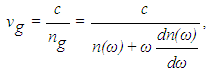
- The group velocity of optical pulse that is propagated in dispersive material can be written as [11]:
 | (1) |
 and
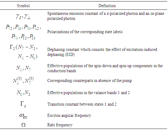
and  stand for refractive index and alterations of refractive index per angular frequency, respectively. Also, c is speed of light in free space. In slow light devices, we require high variations of refractive index in narrow range in order to acquire minimum value of group velocity. The positive slope in refractive index spectrum is created by propagation pump and signal in two-level systems based on V-type EIT. Two-level systems are included light-hole-like (LH-like) subband and conduction band in V-type EIT method [8]. To analyse two-level systems, Bloch equations approach is utilized [7]. Hence, the different effective populations and polarizations equations in our system are described as [8]:
 | (2) |
 | (3) |
 | (4) |
 | (5) |
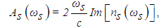
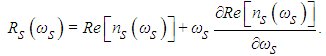
 , we should solve relevant optical equation [12]. By solution of these equations, we can define real part of refractive index, absorption and SDF as follows [13]:
 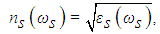 | (6) |
 | (7) |
 | (8) |
|
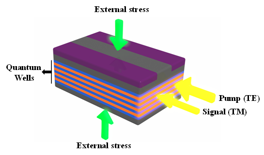 | Figure 1. The schematic sketch of [110] strained quantum wells slow light apparatus according to V-type EIT |
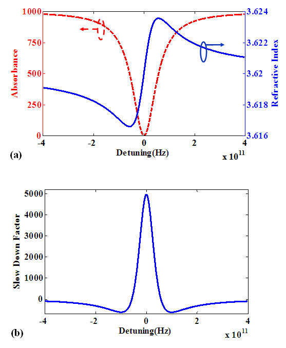 | Figure 2. Spectra of (a) real part of refractive index and absorption (b) slow down factor for the pump-probe scheme of Figure 1. These results have fine agreement with experimental measurements in [8] |
2.2. The Role of Magnetic Field on QWs Structures
- Recently, impacts of applying external fields such as electric and magnetic fields have been investigated on QWs structures. Therefore, we offer to analyze influences of applying external fields on [110] strained QWs slow light devices in this paper. In this part, we look into impacts of applying a magnetic field on QWs structure. The magnetic field is applied perpendicular to QWs layer. To generate this magnetic field, we can use a magnet of polyhelix resistive [14]. Applying this type of field is caused a diamagnetic shift in energy levels of excitons [15]. In the other words, energy levels of excitons enhance by applying a magnetic field. Exciton energy levels determine the central energy or frequency of the slow light system. Thus, we can expect changing in central frequency of strained QWs slow light device by applying magnetic field to the structure. The 1 s state exciton diamagnetic shift as a result of applying a magnetic field is expressed as [15]:
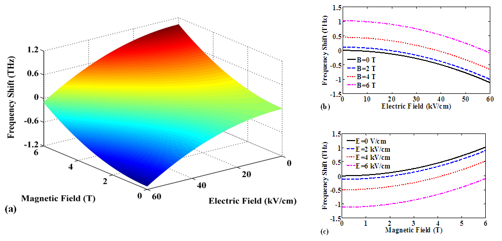
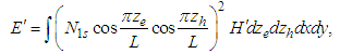 | (9) |
 | (10) |
 is reduced mass and e is electron charge. In summary, excitons energy increases as much as E' by applying a magnetic field that this enhancement is led to shift the central frequency of the device toward higher frequencies.
2.3. The Role of Electric Field on QWs Structures
- In addition to magnetic field, applying an electric field to QWs structures attracts a lot of attention in these days. In this paper, we apply an electric field to [110] strained QWs slow light device. In order to generate electric field, we use current drive or high voltage source [16]. By applying this field, electrons move against direction of electric fields and holes move in direction of it. This response to an applied electric field is caused to a detriment in exciton energy. This phenomenon is called Stark effect [16]. In conclusion, applying an electric field decreases excitons energy that leads to shift the central frequency of device toward lower values.
3. Results and Discussions
- So far, we explained optical characteristics of slow light devices with [110] strained QWs structure and calculated refractive index and slow down factor for them. Additionally, we described the response of QWs structure to variations of electric and magnetic fields. Afterward, we are going to calculate and analyze SDF and refractive index of the slow light apparatus as a function of external fields based on Bloch equations.
3.1. Dependence of Optical Characteristics to an Applied Magnetic Field
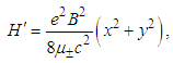
- Figure 3 demonstrates changing in optical properties of structure as a result of applying magnetic field. As shown in Figure 3(a), the central frequency of structure enhances when magnetic field value rises from 0T to 6T. On the other words, it is found that enhancement of magnetic field value creates a positive shift in focal frequency of device. As described in previous part, exciton energy has a relation with the applied magnetic field. Thus, by applying the magnetic field, exciton energy and central frequency of system increase significantly. It should be noted that the slope and size of refractive index are independent of magnetic field amounts. It means that an applied magnetic field does not have any effect on the refractive index value and slope.To get more insight about magnetic field effects, Figure 3(b) illustrates counter plot of refractive index for continues variations of external field. It is obvious that central frequency has down shift with reduction of magnetic field. In addition to refractive index, slow down factor curve changes with applying an external field. Figure 3(c) exhibits SDF for different amounts of magnetic field. As it can be seen in Figure 3(c), the peak value of SDF is constant during increment of magnetic field and just the focal frequency of the device changes. Figure 3(d) displays better view of slow down factor alterations as a function of magnetic field. As observed in this curve, the focal frequency of device rises from 371.3THz to 372.4THz when value of magnetic field increases in range of 6T. In other words, by applying magnetic field in this range, the central frequency of device shifts near 1.1THz in comparison with experimental result that has been explained in [8].
 | Figure 3. (a) Refractive index spectra at different values of magnetic field (B), (b) Evolution of refractive index real part spectra versus Frequency and magnetic field, (c) SDF spectra at different values of magnetic field (B), (d) Evolution of SDF versus Frequency and magnetic field. The experimental data has been described in [8] |
3.2. Dependence of Optical Characteristics to an Applied Electric Field
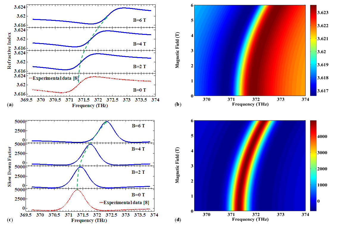
- In this section, we report the impacts of an applied electric field on SDF and refractive index of the strained quantum well slow light system. Figure 4 shows the results of applying an electric field on the device. Figure 4(a) illustrates refractive index spectrum for several amounts of electric field. Obviously, focal frequency of the device reduces when electric field value rises from 0 to 60 kV/cm with steps of 20 kV/cm. Similar to magnetic field, applying an electric field does not have any impact on value and slope of refractive index real part. The decrement of exciton energy as a result of applying an electric field is the reason of central frequency shift. Figure 4 (b) displays behavior of refractive index as a function of frequency and electric field continuously. Based on this contour diagram, applied electric field is caused down shift in central frequency because of exciton energy reduction. One can see that the peak value of SDF is constant, but the focal frequency of it varies when electric field increases, as shown in Figure 4(c). The contour plot of slow down factor is illustrated in Figure 4(d). According to this surface curve, the maximum value of SDF is invariable and close to 5000. When the electric field enhances from 0V/cm to 60kV/cm, central frequency reduces from 371.3THz to 370.2THz based on simulation results. In comparison with experimental measurement [8], the focal frequency of device has negative shift about -1.1 THz by applying electric field in range of 60kV/cm.
 | Figure 4. (a) Refractive index spectra with different electric field (E), (b) Evolution of refractive index real part spectra versus Frequency and electric field, (c) SDF spectra with different electric field (E), (d) Evolution of SDF versus Frequency and electric field. The experimental data has been explained in [8] |
3.3. Response of Slow Light System to Simultaneous Alterations of Electric and Magnetic Fields
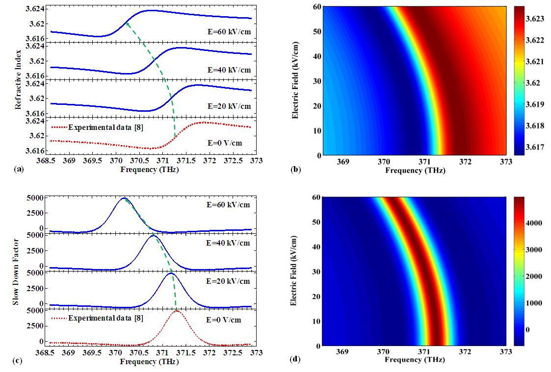
- Until here, we expressed the role of electric and magnetic fields on optical characteristics of the device separately. However, applying electric and magnetic fields at the same time provides appropriate information due to modify central frequency of device. Figure 5(a) demonstrates shift of focal frequency for applying electric and magnetic fields at the same time. According to simulation result, in one hand, focal frequency shift grows gently by enhancement of the applied magnetic field amount. In the other hand, the frequency shift reduces gradually when applied electric field value increases.It is clear from Figure 5(b) that there is a reverse relation between shift of focal frequency and value of applied electric field because increase of electric field value is led to reduce central frequency of device. In contrast, there is a direct connection between amount of applied magnetic field and central frequency shift, as shown in Figure 5(c). So that, the focal frequency gets higher values by increment of applied magnetic field.
 | Figure 5. (a) Response of central frequency to simultaneous variations of electric and magnetic field. (b) Central frequency shift as a function of electric field for different values of magnetic field. (c) Central frequency shift as a function of magnetic field for different values of electric field |
4. Conclusions
- In this article, we have analysed and explained [110] strained QWs slow light devices based on V-type EIT. We have shown the optical properties of the device under applied external fields. Meanwhile, we have compared our simulation consequences with experimental results in [8]. As a result of simulations, applying a magnetic field to proposed structure leads to a positive shift in the focal frequency of device. Also, applying an electric field shifts the central frequency of system to lower values. According to the achieved results from Bloch equations, applying external fields have no effect on peak value of slow down factor. By comparison of presented method in this paper with experimental results in [8], we could create up shift about 1.1THz and down shift close to -1.1 THz in central frequency of device. The obtained results are suitable in order to control central frequency of systems that strained QWs slow light apparatus is one of the important sections of them.