-
Paper Information
- Next Paper
- Paper Submission
-
Journal Information
- About This Journal
- Editorial Board
- Current Issue
- Archive
- Author Guidelines
- Contact Us
International Journal of Optics and Applications
p-ISSN: 2168-5053 e-ISSN: 2168-5061
2017; 7(2): 37-41
doi:10.5923/j.optics.20170702.02

Group Delay Enhancement for Slow and Fast Light in Silicon Microring Resonator Structures
 Abstract
 Reference
 Full-Text PDF
 Full-text HTML
Behnoush Babaghorbani, Hassan Kaatuzian
Photonics Research Laboratory, Electrical Engineering Department, Amirkabir University of Technology, Tehran, Iran
Correspondence to: Hassan Kaatuzian, Photonics Research Laboratory, Electrical Engineering Department, Amirkabir University of Technology, Tehran, Iran.
| Email: |  |
Copyright © 2017 Scientific & Academic Publishing. All Rights Reserved.
This work is licensed under the Creative Commons Attribution International License (CC BY).
http://creativecommons.org/licenses/by/4.0/

Single - and double-waveguide coupled resonators are designed and analyzed according to Silicon On Insulator (SOI) technology. In the last few decades much study has been done on the Microring Resonators (MRRs). In order to enhance group delay, many different structures have been proposed and constructed. In this theoretical study, by variation of coupling coefficient in terms of altering distance gap between ring and waveguide, we’ve successfully simulated and estimated high group delay for slow and fast light in microring with radius of  50µm. Compared with previously reported experimental results, time delay is improved significantly from 32 ps to 166 ps, which is increased considerably. Also, fast light is observed in single waveguide structure with a maximum time advance of 114 ps. For double waveguide structure, by changing the coupling coefficient, time delay is also improved significantly. Another port of this structure is monitored, simultaneous slow and fast light achieved at single frequency with certain coupling condition.
Keywords: Microring resonator, Slow and fast light, Silicon waveguide, Transmission and group delay
Cite this paper: Behnoush Babaghorbani, Hassan Kaatuzian, Group Delay Enhancement for Slow and Fast Light in Silicon Microring Resonator Structures, International Journal of Optics and Applications, Vol. 7 No. 2, 2017, pp. 37-41. doi: 10.5923/j.optics.20170702.02.
Article Outline
1. Introduction
- In recent years, there has been a growing interest towards finding applications in photonic devices. Slow and fast light techniques can be used to obtain significant adjustments for group velocity of light pulses through a medium. Generating slow and fast light signals, have become so attractive in research topics during recent years. In order to control the delay or advancement of optical signals, much of the studies have been concentrated on development of these techniques. For example a number of theoretical and experimental works in this area have been reported in [1]. Slow and fast light devices have been intensely studied because of their specific properties for affecting the flow of light and light-matter interactions. By using optical data transmission through photonic integration, significant saving in power consumption, cost and volume are possible. Photonic techniques overcome the restriction of conventional electronics technology i.e. bandwidth. Many applications such as optical buffer, optical memory, tuneable optical delay line, all optical switch, data synchronization, synthetic aperture radars, cryptography and nonlinear optics have been demonstrated recently [2-4]. Slow and fast light can be generated with different mechanisms. For example: Coherent Population Oscillation (CPO) [5], Stimulated Raman Scattering (SRS) [6], Stimulated Brillouin Scattering (SBS) in optical filters [7, 8] and Electromagnetically Induced Transparency (EIT) in atomic vapour [9] based on material resonances. Another mechanism for controlling the velocity of light is to utilize dispersive structures, such as Bragg grating [10], photonic crystal waveguides and cavities [11], microsphere resonators and micro-ring resonators [12]. The above optical devices based on dispersive structure are able to work in room temperature, more compact and compatible with modern advance fabrication technology.Silicon on Insulator (SOI) technology, has become a favourable platform for highly compact photonic devices due to compatibility with CMOS technology and high index contrast between core and cladding. The process of fabrication can be taken from electronic industry. SOI based microring resonators (MRRs) have received intense attention. A typical MRR consists of a bus waveguide and a microring which coupled by a Directional Coupler (DC) or a Multimode Interference coupler (MMI). In DC, by altering the distance between bus and microring, coupling is changed but the loss penalty is observed [13]. MMI based MRRs characteristics have a larger resonance bandwidth and a lower Q factor respect to DC ones. MRRs have extreme miniaturization, compact size, simple structure and large delay among several resonance structures. These devices are interesting and useful for integrated optics and photonic applications. MRRs have been merged in optical sensing, filtering, switching and wavelength division multiplexing by add-dropping filters [14-16]. Add-drop filters using MRRs due to ease of fabrication and capability for on chip design have been used recently. Slow and fast light can be achieved in a single device by changing the spacing gap, input polarization and wavelength. MRRs similar to Fabry-Perot are explained as filters and can be used for higher order filters with expanded free spectral range, switching, fast and slow light. MRRs can be used in different structures, such as elliptic-resonators [17]. Also MRRs may be constructed in series or in parallel. There are two main series structure which have been suggested theoretically and experimentally: Coupled Resonator Optical Waveguide Resonators (CROWs) [18] and Side Coupled Integrated Spaced Sequence of Resonators (SCISSORs) [19]. Both these structures have the potential to alter the propagation of light. SCISSORs show smoother spectral while CROWs demonstrate a noisy characteristic because of fluctuation in the coupling strength.The rest of the paper is organized as follows. In section 2, we will describe in brief the theoretical viewpoints of coupled mode theory and it’s applications in ring resonators. In section 3 simulation results demonstrates the effect of design parameters such as coupling and loss in the characteristics of the device. Finally, the conclusion are drawn in section 4.
2. Wave Coupling Theory in Ring Resonators
- In this section, transmission and group delay characteristics for single- and double-waveguide coupled resonator are studied in brief. These general transmission functions are derived from coupled mode theory or transfer matrix method [18, 20] that described in details in the next sections. Using MATLAB code in order to calculate magnitude and effective phase shift of coupled structures. Group delay also is obtained and is proportional to derivative of the effective phase shift respect to radian-frequency. It can be calculated via MATLAB simulation.
2.1. Single Waveguide Coupled Resonator
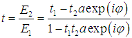
- The relation between incident, circulating and output fields of ring resonator is established from coupled mode theory. Using the notation of Fig. 1, the coupling can be depicted by [20, 21]
 | (1) |
 | (2) |
 is the power self-coupling coefficient. The relation
  is between two real qualities. When light in the bus waveguide is coupled to the ring, it experiences round trip phase shift φ in the circulation. Also the amplitude of transmission decreased caused by loss. The resulting expression is
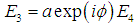 | (3) |
 is the power loss factor and
  denotes the accumulated phase shift over the ring waveguide
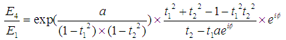
 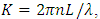 L is the ring cavity length, n is the effective refractive index of ring waveguide and λ is the wavelength of input light in vacuum. By solving these 3 lately equations at the same time, the normalized transmission response of ring resonator is obtained as
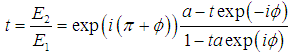 | (4) |
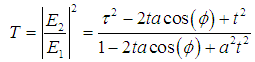 | (5) |
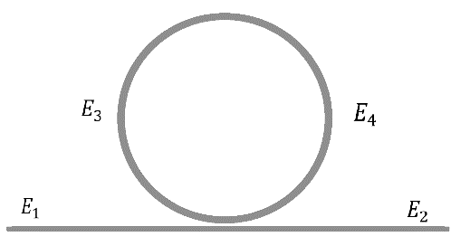 | Figure 1. Schematic diagram of single waveguide coupled resonator |
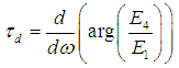
 and the group delay
  , respectively, denoted as
 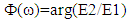 and
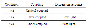
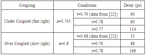
and  Table 1. Summarizes characteristics of single waveguide coupled resonators. Fast
  and slow
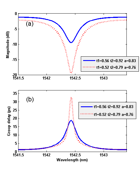
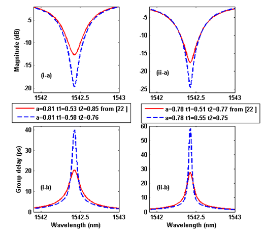
  light can be realized under certain conditions.Using coupling and loss parameters in [22], the transmission and group delay can be simulated from above general equations (Fig. 2). As can be seen these results agree with the content of Table 1.
|
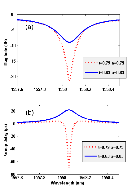 | Figure 2. Theoretical results. (a) Magnitude, and (b) group delay of single waveguide coupled resonator for two different coupling conditions |
2.2. Double Waveguide Coupled Resonator
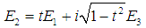
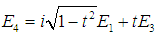
- The schematic diagram of double-waveguide coupled resonator is depicted in Fig.3. The transmission response of port 2 can be calculated from transfer matrix method and expressed as [20]
 | (6) |
 and
and  , respectively, are self-coupling coefficients of coupler 1 and coupler 2. The intensity transmission factor and group delay can be obtained
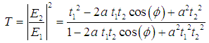 | (7) |
 | (8) |
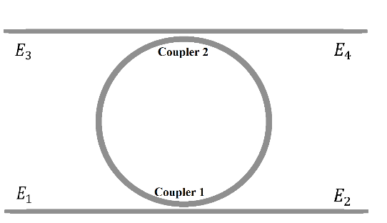 | Figure 3. Schematic diagram of double waveguide coupled resonator |
 | Figure 4. Theoretical results. (a) Magnitude, and (b) group delay of double waveguide coupled resonator for different coupling conditions |
3. Simulation Results and Discussions
- In this work, the effects of variation of parameters are analysed and simulated. Due to the coupled mode theory, the coupling coefficient depends on several design and structural parameters such as distance gap between ring and waveguide.Ring resonators can produce slow and fast light. Their applications are in optical delay lines and optical buffers, so on. Several structures have been proposed until now such as double-knot resonator structure [23]. The main purpose is improvement of structural characteristics in order to produce adjustable slow and fast light and to increase group delay and operation bandwidth. Adjustable slow and fast light can be achieved by using mutual mode coupling [24]. Here, we are going to increase group delay. This considerable improvement is obtained by optimization parameters which is existed in transmission relation.The SOI platform provides highly compact photonic devices. The accumulated phase shift Ф is constant for a certain value of L at operating wavelength. According to the equation in the previous section, the transfer function is only affected by coupling and loss coefficient. In these systems, the amount of loss is expressed by dB/cm, therefore for a fix structure, the amount of loss is nearly constant. By varying the distance gap between ring and waveguide, coupling coefficient is altered. In such a way the coupling coefficient is decreased with increasing the gap distance. Optimized coupling coefficient can be obtained by mathematical analysis.
3.1. Single Waveguide MRR
- Consider a single waveguide coupled to ring with 340µm circumference of the ring in SOI structure. According to Table 1 slow and fast light can be achieved in under and over coupled, respectively. Our simulations agree with experimental and measured results in [22], under same coupling and loss conditions. The optimized coupling coefficient is extracted and simulated in Fig.5 and final results are collected in Table 2.
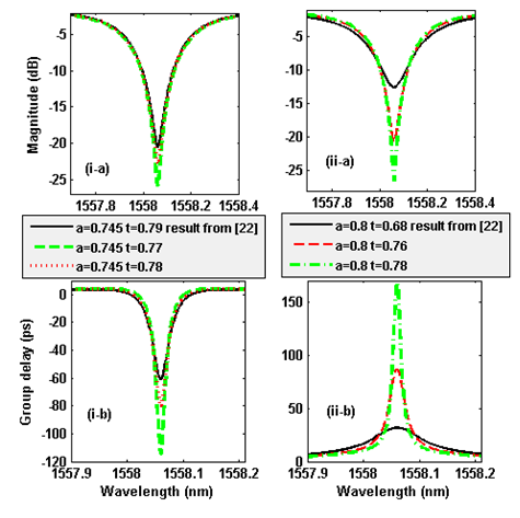 | Figure 5. Simulation results. (a) Magnitude, and (b) group delay for under coupled (i) and over coupled (ii) condition |
|
3.2. Double Waveguide MRR
- Based on calculations for double waveguide coupled resonator, the coupling coefficient
 and
and  are set, respectively 0.55 and 0.75. Simulation results are compared with experiments in [22] with the same condition for loss coefficient. Group delay is increased which means, this proposed structure has more buffering capacity. Fig.6 shown magnitude and group delay for different coupling coefficients of
  and
and  with equal loss factor. Group delay enhanced from
  to
to  .
. | Figure 6. Simulation results. (a) Magnitude, and (b) group delay for two different loss factor |
 | (9) |
 | (10) |
 ,
,  and loss are used. Outputs of port 2 and port 4 are drawn in Fig.7. As can be seen, both slow and fast light can be achieved in this device at single wavelength.
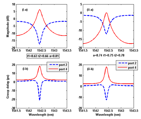 | Figure 7. Simulation results. (a) Magnitude, and (b) group delay of double waveguide. Light pulse propagate as slow from port 4 and as fast light from port 2 |
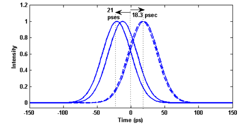 | Figure 8. Output of port 2 and port 4 for two different coupling setting. Simultaneous slow and fast light achieve |
4. Conclusions
- In summary, the transmission function is used to analyse group delay of single- and double-waveguide coupled resonator in SOI technology. This structure can produce slow and fast light by controlling the coupling coefficient. Transmission relation can be obtained from coupled mode theory or transfer matrix method. We study pulse propagation through single and double waveguide with different coupling setting. Simulation results with initial values for coupling coefficient agree with previous experimental ones. Coupling coefficient is optimized by variation of distance gap between ring and waveguide and group delay is enhanced and doubled for double waveguide coupled resonator respect to experimental results in the same structure and loss coefficient. Similarly for single waveguide coupled resonator group delay is enhanced from 32 ps to 166 ps for slow light and increased from 60 ps to 114 ps for the fast light. Also, simultaneous slow and fast light is investigated in double waveguide coupled resonator. Two ports are used as outputs to produce time delay and advance at single frequency. This structure is particularly important in applications.