Faramarz E. Seraji1, Marzieh Sadat Kiaee2
1Optical Communication Group, Iran Telecom Research Center, Tehran, Iran
2Electrical Engineering Department, Ghiasodin Jamshid Kashani Inst. of Higher Edu, Abyek, Qazvin, Iran
Correspondence to: Faramarz E. Seraji, Optical Communication Group, Iran Telecom Research Center, Tehran, Iran.
| Email: |  |
Copyright © 2017 Scientific & Academic Publishing. All Rights Reserved.
This work is licensed under the Creative Commons Attribution International License (CC BY).
http://creativecommons.org/licenses/by/4.0/

Abstract
In this evaluation, we have compared two popular return to zero (RZ) and non-return to zero (NRZ) modulation formats in a 100-km and 400-km single-channel and wavelength division multiplexing (WDM) optical networks for bit rate of 10-Gb/s and 160-Gb/s, respectively, by using Optisystem software. The results showed the better performance of the RZ technique in tolerating the non-linear effects and noisy environments. It’s shown that NRZ technique is a good option for single-channel networks and long-haul WDM links. The obtained evaluation results show that the RZ technique is a better choice for short-distance WDM links.
Keywords:
External Modulation, Direct Modulation, Optical Link, RZ, NRZ, WDM System
Cite this paper: Faramarz E. Seraji, Marzieh Sadat Kiaee, Eye-Diagram-Based Evaluation of RZ and NRZ Modulation Methods in a 10-Gb/s Single-Channel and a 160-Gb/s WDM Optical Networks, International Journal of Optics and Applications, Vol. 7 No. 2, 2017, pp. 31-36. doi: 10.5923/j.optics.20170702.01.
1. Introduction
Return to zero (RZ) and non-return to zero (NRZ) are the popular techniques, which are used to encode optical pulses in optical networks. In a simple comparison, the NRZ technique requires less bandwidth for transmission than the RZ and it is not sensitive to laser phase noise. Also, while the NRZ is more economical, the RZ, on the other hand, is more tolerant to nonlinearity than the NRZ [1].In a study, the RZ and the NRZ techniques have been compared in an optical duobinary system. The results showed that NRZ pulse shape was superior compared with RZ for duobinary transmission in all the cases that were studied including systems that are limited by amplified-spontaneous noise, fiber chromatic dispersion and self-phase modulation [2].Another study has been done to compare standard forward error code (FEC) in 40 Gb/s optical transmission systems with NRZ, RZ, and carrier-suppressed RZ (CS-RZ) modulation formats. The results showed the NRZ format had a similar tolerance to intersymbol interference due to the interaction of dispersion and nonlinearities as that of RZ and CS-RZ formats without FEC [3]. A comparison between the NRZ and the RZ data formats with respect to polarization mode dispersion (PMD)-induced system degradation showed the RZ performance better than the NRZ [4].Another comparison between the RZ and the NRZ modulation formats for 40-Gb/s time division multiplexing (TDM) system, showed that for upgrading the existing network to 40-Gb/s, the RZ-modulation format is superior compared to conventional NRZ-modulation. They reported that transmission distances of 400 km and 1200 km with bit rate of 40 Gb/s are feasible within the RZ- and the NRZ-modulation formats [5].The effects of amplified spontaneous emission in the networks with the RZ, the NRZ, and the CS-RZ modulation formats were evaluated by using an Erbium-doped fiber amplifier (EDFA). The results showed the smaller bandwidth was required by using NRZ format, while better performance of the RZ format was obtained to withstand fiber non-linearity effects [6].A comparison of the RZ and the NRZ modulations in laser intra-satellite communication systems showed that by using an amplifier, the RZ format had a better performance for a long transmission distance; and without an amplifier, the RZ- and the NRZ-modulation formats had the same performance [7].In a 2.5-Gb/s optical network, the RZ- and the NRZ-modulation formats have been compared, where the BER for the network with the NRZ- and the RZ-modulation techniques were 10-14 and 10-12, respectively, with 30-km single-mode fiber link. The results of this study showed the better performance of the NRZ format [8].Another comparison between the RZ- and the NRZ-techniques has been reported in a 4-users WDM system with bit rate of 2.5-Gb/s per channel. The results for transmission distance of 400 km showed the BER of 10-22 and 10-9 for the RZ- and the NRZ modulation techniques, respectively. They reported better performance of the RZ modulation format [9]. Recently, we have designed a 160 Gb/s DWDM network with transmission power of 0 dBm, using NRZ encoding technique through a 32-chanels optical transmitter over a distance of 1000 km [10]. In the present study, we have compared the NRZ- and the RZ-modulation techniques in a 400-km/10-Gb/s single-channel and a 400-km/160-Gb/s WDM networks. The analyses are based on eye-diagrams of the simulated received signals in each case.
2. Design of Optical Link
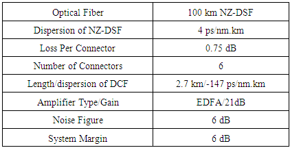
We have designed an optical network to be used as a single-channel wavelength division multiplexing (WDM) link, by using Optisystem software. To this aim, we have designed a span including a 100-km non-zero dispersion shifted fiber (NZDSF), 2.7 km of dispersion compensating fiber (DCF), an EDFA with a gain of 21 dB and six connectors with a total loss of 4.5 dB.We have built a loop control in the network to increase the number of spans for each design step, as shown in Fig. 1. Each loop is equivalent to 100 km fiber. In Table 1, the parameters of the designed optical link are tabulated.To start with, first the loop was set on 1 and in another attempt; it was set on 4 for 100-km and 400-km transmission distances, respectively. We have used this network as a base for designs of single-channel and WDM optical links to evaluate the RZ- and the NRZ-modulation techniques in each network case. 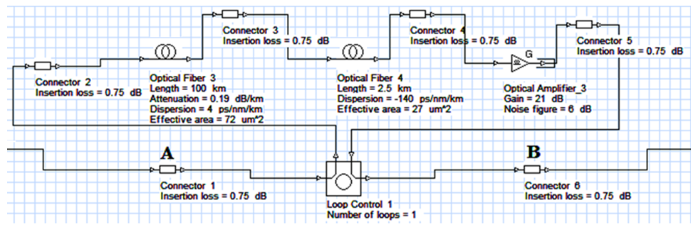 | Figure 1. The designed optical link |
Table 1. Parameters of the designed optical network
 |
| |
|
3. Simulation of Single-Channel Optical Link
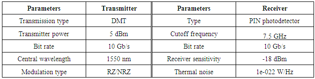
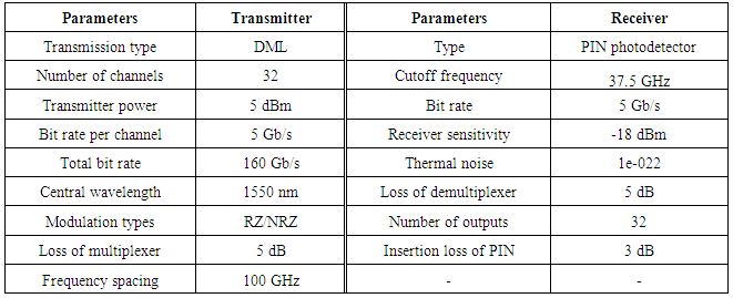
To design a single-channel optical network, the base optical link of Fig. 1 is employed and inserted between point A and B of Fig. 2, interconnecting the transmitter and receiver that are designed, by using the selected design parameters given in Table 2. The full diagram of the designed single-channel optical network is depicted in Fig. 2, which is used to modulate single wavelength based on the RZ/NRZ techniques. Each employed connector has a loss of 0.75 dB.The transmitter was set on direct modulation technique (DMT), where the light wave propagates through the fiber without using an external modulator. In the receiver side, a PIN photodetector is used with a bit rate (B) of 10 Gb/s and cutoff frequency of (0.75B) Hz. The receiver sensitivity and noise figure are -18 dBm and 6 dB, respectively.Throughout our analysis, the parameters of the eye-diagrams, which are obtained by the Optisystem software, are used. Now, by using the RZ- and the NRZ-modulation formats, in a 100-km and a 400-km transmission distances will result in the eye-diagrams of the respective received signal, as shown in Figs. 3 for comparisons.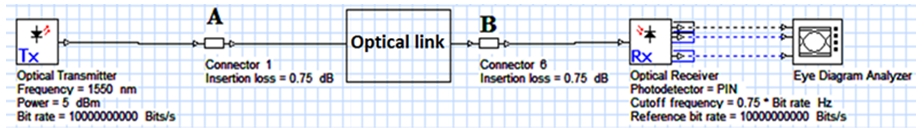 | Figure 2. Block-diagram of the designed single-channel network |
Table 2. Parameters of the transmitter/receiver used for RZ/NRZ single-channel network
 |
| |
|
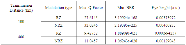
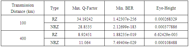
Table 3 shows the numerical parameters of the received signals from the 100-km/400-km single-channel optical networks. In the single-channel network, we have examined the effects of RZ and NRZ modulation techniques for the 100-km and 400-km transmission distances with a bit rate of 10 Gb/s by using the eye-diagram parameters.Comparing the eye-diagrams in Fig. 3 will show a low level noise because of the ideal height opening of the eye diagrams. The amplitude (the height between points A and E) of the eye achieved from the NRZ format is higher than that of the RZ, which shows a higher received power and easier detection of the NRZ signals by the receiver. It is noted in Table 3 that the higher quantity of Q-factor and the eye-height (the length between points B and D for NRZ and the points h and I for RZ technique) and lower BER of the NRZ received signals show a better performance of this technique as compared to the RZ format. The jitter (the width between points F and G) is low in both methods for 100-km transmission distance.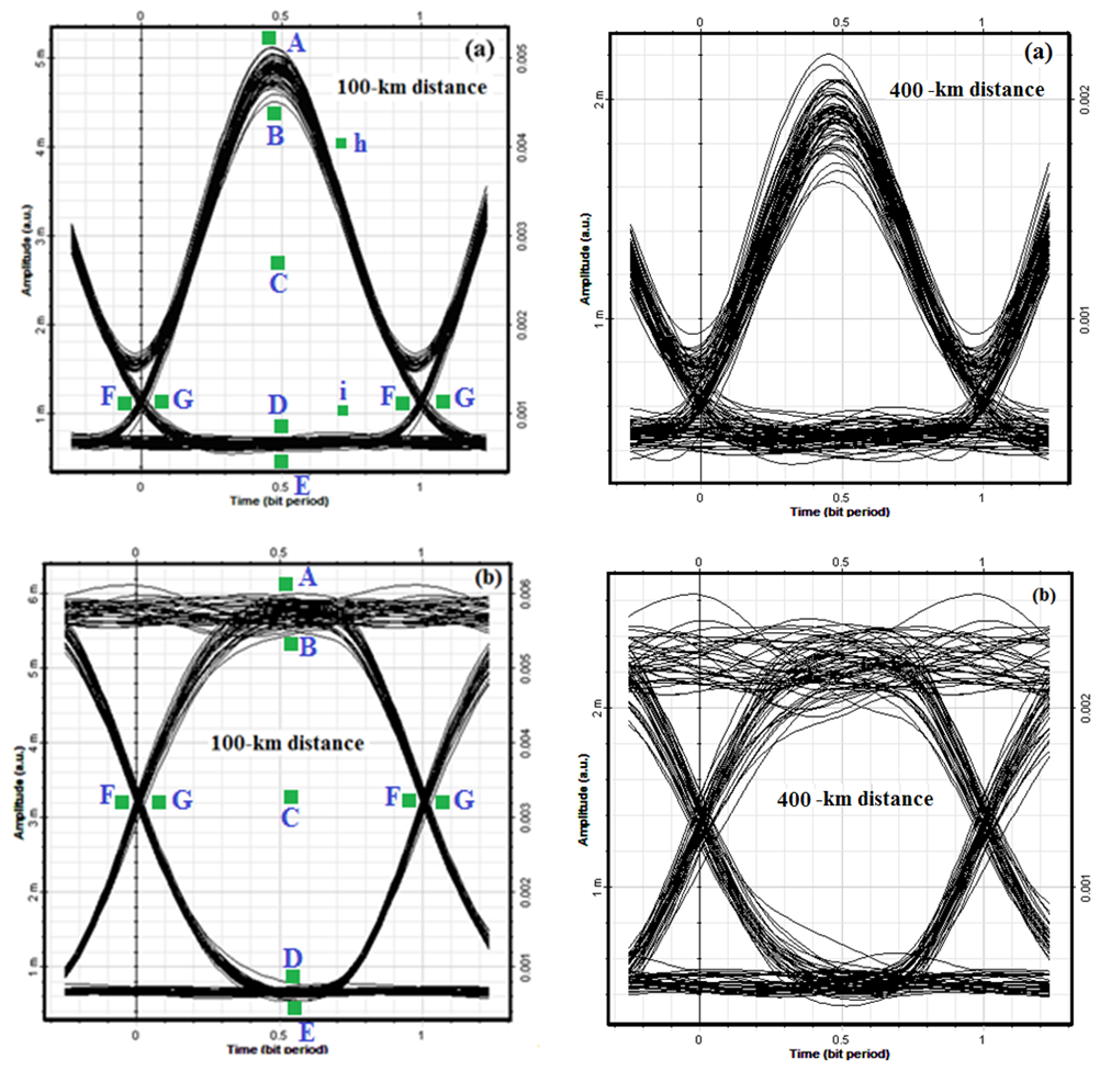 | Figure 3. The eye-diagram of the received signals from 100-km and 400-km single-channel networks by using (a) RZ and (b) NRZ modulation formats, respectively |
Table 3. Parameters of the received signal for the different distances of the single-channel networks
 |
| |
|
For transmission distance of 400-km, the distortion (the distance between points A and B) can be observed at high-levels of both the eye-diagrams; but as we can see, the RZ format presents lower levels of non-linearity effects on the received signals. According to the ideal eye-height, the signal-to-noise ratio (SNR) (the height between points B and C) is acceptable and the signals have enough power to be detected by the receiver. The numerical parameters in Table 3 show a better performance of the NRZ modulation technique due to the higher SNR and eye-height, and a lower BER. But in long-haul systems, which are affected by distortion and noise, using RZ modulation technique is recommended.
4. Simulation of WDM Link
With a similar procedure, a WDM link is made by connecting a transmitter to point A and a receiver to point B. We have used the 32-channel WDM transmitter with a bit rate of 5 Gb/s by using NRZ- and RZ-modulation techniques for distances of 100 km and 400 km, as illustrated in Fig. 4. The full characteristic parameters of the transmitter and receiver are given in Table 4.The eye-diagrams of the received signals from 100-km and 400-km distances of the WDM network with bit rate of 160 Gb/s by using RZ- and NRZ-modulation formats, as depicted in Fig. 4. The parameters of the eye-diagrams for the received signals from 100-km and 400-km WDM links based on RZ- and NRZ-modulation techniques are tabulated in Table 4.Comparing the eye-diagrams in Fig. 5 will show that both the techniques have transmitted signals symmetrically, because occurring rise/fall times in the consecutive periods are at the same points. The NRZ signals have higher amplitudes, indicating that high-power signals are received by using this technique. The parameters in Table 5 indicate that by using RZ technique for 100-km WDM link, a higher Q-factor and lower BER are attained. In both methods, distortion in logic 1 is evident, but it does not cause to disturb the signal shapes.By increasing the transmission distance up to 400 km in the WDM link, noise and distortion of the NRZ signals were more than that of the RZ signals. However, the amplitudes of the NRZ signals were higher than that of the RZ signals. Numerically, as we can see in Table 5, the NRZ signals have a higher Q-factor and an eye-height, and lower BER, indicating a better performance of signal-to-noise, resulting in a less erroneous transmission.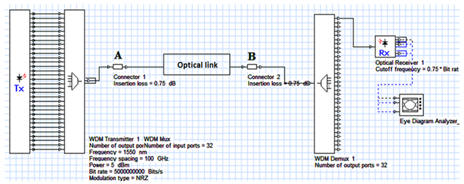 | Figure 4. Block-diagram of the designed WDM Network |
Table 4. Characteristic parameters of the designed WDM transmitter and receiver
 |
| |
|
 | Figure 5. The eye-diagrams of the received signals from 100-km and 400 km WDM networks by using (a) RZ and (b) NRZ modulation techniques |
Table 5. Parameters of the eye-diagram of the received signal from WDM network
 |
| |
|
5. Discussions
In a study, the RZ/NRZ techniques were compared and reported the RZ technique as a better modulation format because of its less PMD in transmission [4]; not only PMD, but also some other parameters are effective in choosing one method between the two, which are affected by non-linear properties of fiber that should be considered in final choice.In an article, the RZ and the NRZ methods were compared; the results showed the same performance for both the methods [3]. This comparison only checked intersymbol interference (ISI) in a 40 Gb/s network, but the question is that how the results would appear by increasing/decreasing the bit rate, transmission distance or number of wavelengths?In another study which was done on communicating satellites, the selected better formats for long- and short-transmission distances, were the RZ and the NRZ techniques, respectively [7]. The point is that to choose a better technique when the number of users are increased, thus we need implementing a WDM network. A comparison between the RZ and the NRZ techniques with/without EDFA in transmission link was done and the results showed better performance with NRZ method for both the cases [8].
6. Conclusions
In this paper, we have evaluated the influences of the RZ/NRZ modulation techniques in a single-channel and WDM networks for transmission distance of 100 km and 400 km by using Optisystem software. The results have been analyzed based on the eye-diagrams of the received signals obtained in each case. The obtained results show that the RZ modulation technique has a better performance in noisy environments and situations where distortions affect on the transmitted signals. In the 10-Gb/s single-channel optical networks, using NRZ modulation technique is recommended, because of its low BER and high Q-factor for both 100-km and 400-km optical transmission network.In the 160-Gb/s WDM network, the RZ technique had a better performance due to the higher Q-factor and lower BER for short distances. On the other hand, the NRZ technique had a better performance in long-haul WDM network, but with more vulnerability from fiber non-linearity and noises.
References
| [1] | Chris Xu, Xiang Liu, Linn F. Mollenauer, and Xing Wei, “Comparison of return-to-zero differential phase-shift keying and on-off keying in long-haul dispersion managed transmission”, IEEE Photon. Technol. Lett., Vol. 15, No. 4, pp. 617-619, 2003. |
| [2] | Cheng-Chung Chien and Ilya Lyubomirsky, “Comparison of RZ versus NRZ Pulse Shapes for Optical Duobinary Transmission”, J. Lightwave Technol., Vol. 25, pp. 2953-2958, 2007. |
| [3] | Juanjuan Yan, Minghua Chen, Shizhong Xie, and Bingkun Zhou,” Performance Comparison of Standard FEC in 40Gbps Optical Transmission Systems with NRZ, RZ and CS-RZ modulation formats”, Opt. Commun., Vol. 231, pp. 175-180, 2004. |
| [4] | H. Sunnerud, M. Karlsson, and P. A. Andrekson, “A Comparison between NRZ and RZ Data Formats With Respect To PMD-Induced System Degradation”, Opt. Fiber Commun. Conf. and Exhibit, 17-22 March, No. 7137476, Anaheim, CA, USA, 2001. |
| [5] | D. Breuer and K. Petermann, “Comparison of NRZ- and RZ-modulation Format for 40 Gbps TDM Standard-Fiber Systems”, IEEE Photon. Technol. Lett., Vol. 20, pp. 598, 2002. |
| [6] | J. Kaur and N. Sharma, “Effects of Amplified Spontaneous Emission on NRZ, RZ and CS-RZ modulation Formats in Single Channel Light-Wave System”, Emerging Trends in Networks and Computer Communications, No. 12121408, pp. 61-64, 2011. |
| [7] | N. Liu, W. D. Zhoung, Y. He, K. H. Heng, and T. H. Cheng, “Comparison of NRZ and RZ Modulations in Laser Intersatellite Communication Systems”, Int’l Conf. Advanced Infocomm Technol., No. 55, New York, USA, 2008. |
| [8] | Muthana Y. Aldouri, S. A. Aljunid, R. Badlishah Ahmad, and Hilal A. Fadhi, “BER Performance of RZ and NRZ Data Signals Optical Code Division Multiple Access System Based on AND Detection Scheme In Fiber to the Home Network”, Optica Apllicata, Vol. 21, No. 10, pp. 9-13, 2011. |
| [9] | Jaswinder Singh, “NRZ Vs. RZ: Performance Analysis for Fiber-Optic CDMA”, J. Eng. Research and Studies, 2011. |
| [10] | Marzieh Sadat Kiaee and Faramarz E. Seraji, “Design of a 32×5 Gb/s DWDM Optical Network over a Distance of 1000 km”, Int’l. J. Opt. Appl., Vol. 6, No. 2, pp.31-36, 2016. |

 Abstract
 Reference
 Full-Text PDF
 Full-text HTML