-
Paper Information
- Paper Submission
-
Journal Information
- About This Journal
- Editorial Board
- Current Issue
- Archive
- Author Guidelines
- Contact Us
International Journal of Optics and Applications
p-ISSN: 2168-5053 e-ISSN: 2168-5061
2016; 6(2): 31-36
doi:10.5923/j.optics.20160602.02

Design of a 32×5 Gb/s DWDM Optical Network over a Distance of 1000 km
 Abstract
 Reference
 Full-Text PDF
 Full-text HTML
Marzieh Sadat Kiaee, Faramarz E. Seraji
Optical Communication Group, Iran Telecom Research Center, Tehran, Iran
Correspondence to: Faramarz E. Seraji, Optical Communication Group, Iran Telecom Research Center, Tehran, Iran.
| Email: |  |
Copyright © 2016 Scientific & Academic Publishing. All Rights Reserved.
This work is licensed under the Creative Commons Attribution International License (CC BY).
http://creativecommons.org/licenses/by/4.0/

Growing demands of the internet users is one of the reasons that lead using dense wavelength division multiplexing (WDM) networks to transmit optical data. This modulation technique has the capability of transmitting several wavelengths through a single optical fiber. In this study, we have simulated a 160 Gb/s DWDM network with transmission power of 0 dBm, using NRZ encoding technique through a 32-chanels optical transmitter over a distance of 1000 km. To this aim, we have assumed a link of 10 spans with a length of 100 km fiber for each span. An EDFA and a DCF have been used for amplifying signals and compensating pulse dispersion, respectively. All simulations have been run by using Optisystem software. The quality of the network was estimated by using the eye-diagrams of the received signals. The maximum quality factor of 20.7 and minimum bit error rate of 7.6×10-95 are obtained at wavelength of 1552.5 nm. The eye-diagrams showed an ideal quality for the received signals. More research works are needed to evaluate the parameters that affect on the quality of the DWDM optical systems.
Keywords: 160 Gb/s, DWDM network, Long-haul transmission
Cite this paper: Marzieh Sadat Kiaee, Faramarz E. Seraji, Design of a 32×5 Gb/s DWDM Optical Network over a Distance of 1000 km, International Journal of Optics and Applications, Vol. 6 No. 2, 2016, pp. 31-36. doi: 10.5923/j.optics.20160602.02.
Article Outline
1. Introduction
- Dense wavelength division multiplexing (DWDM) is a technique by which multiple optical signals may be transmitted through optical fibers with closely spaced wavelengths. The DWDM systems operate at a central wavelength of 1550 nm due to the low attenuation. According to the ITU-T standards, the channels are separated by a spacing of 100 GHz [1]. There are some articles that have studied high bit rate systems using WDM technology [2-4]. In a study, a long-haul WDM link was designed using 224 Gb/s polarization-multiplexed 16-QAM [2]. The signal to noise ratio (SNR) of 23.4 was achieved for the distance of 1200 km through a WDM link. A 40-Gb/s WDM system for the distance of 400 km was demonstrated using cascaded chirped fiber grating to compensate the dispersion [3]. The power penalty of transmission in each channel was less than 2-dB while bit error rate (BER) was reported as 10-10. Another study has simulated a 400 Gb/s unamplified WDM system over a distance of 40 km through a single-mode fiber [4]. This link was planned on C-band and employed modulation technique of dual-polarization quadrature phase shift keying (DP-QPSK). The analysis showed an error-free operation, i.e., BER>1×10-13.In this study, we have presented a design of a 32x5 Gb/s DWDM optical network over a distance of 1000 km using not-return to zero (NRZ) encoding technique. All simulations have been run by OPTISYS and MATLAB Softwares.
2. Design Procedures
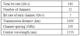
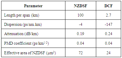
- For design of a 32x5 Gb/s DWDM optical network, we have assumed a DWDM network with 32-channels with the parameters listed in Table 1. The bit rate of each channel is 5 Gb/s and channel spacing of 100 GHz is assumed based on the ITU-T standard [5]. The central wavelength for this network is set on 1550 nm and a total span of 1000 km is considered for the transmission line distance. The steps of designing this network, consisting of transmitter block, optical transmission link, and receiver block, respectively, are as follows.
|
2.1. Design of the Transmitter Block
- For the design of transmitter block, we have used a pseudo-random bit sequence generator with the bit rate of 5 Gb/s connected to a NRZ pulse generator. NRZ modulation technique has been employed, because its generated pulses are not sensitive to laser phase noise and does require smaller bandwidth in comparison to return-to-zero (RZ) modulation. This method is cost effective and suitable for WDM systems due to the more reliable detection [7]. In addition, a continuous wave (CW) laser with the transmitting power of 0 dBm has been chosen and C-band wavelengths were assigned to the CW lasers in order to modulate the data.NRZ pulse generator and CW laser were connected to a Mach-Zehnder modulator (MZM). Studies show that at long distances and having large number of users, the BER of the received signals in the case of external modulation (EM) is significantly less than that of direct modulation (DM) [8]. The required electro-optic components were separately coupled to a 32-channel multiplexer with the insertion loss of 5 dB.
2.2. Design of the Optical Transmission Link
- We have chosen non-zero dispersion shifted fiber (NZDSF) as a transmission medium due to its low attenuation at the operating wavelength of 1550 nm [9]. By using standard fiber length of 25 km on a spool available in the market, the total link distance of 1000 km requires 40 numbers of spools. To calculate the power budget, we have used the following expression to find the received signal power
 required by the link.
 | (1) |
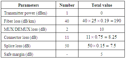
 and SM are transmitted power, losses of fiber, splice joint, connector, multiplexer, demultiplexer, and safe margin, respectively. By using the parameters values listed in Table 2, the power budget of the transmission link is obtained as -250.75dBm.
|
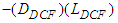 to that of the transmission fiber
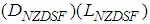 expressed as follows [11]:
 | (2) |
 are the respective lengths and dispersion coefficients of corresponding fibers. The length of DCF obtained in this case is 1.7 km. For this network, Erbium-doped fiber amplifier (EDFA) is chosen and a standard minimum amplifier power
  is taken as -26 dBm [13], which is expressed as follows for the proposed link:
 | (3) |
 is the fiber attenuation coefficient, M is the total number of spools in a span, SM represents safe margin,
  denotes the length of span, and
  ,
,  ,
,  ,
,  are splice loss in NZDSF fiber length, losses of splice joints to the DCF and the EDFA, and connector loss, respectively. Replacing the parameters values from Table 2 in Eq. 3, the required total number of fiber spools M is obtained as 4 pcs. So, we have considered 10 spans each containing 4×25 km of fiber to provide total 1000 km transmission distance.Table 3 lists the numerical parameters of the NZDSF and the DCF used in the optical network. We have used 4 splice joints to connect fiber segments in each span, so the total number of splice joints for 1000 km, including splices used for the DCF and EDFA was 50. Also, we have used one connector to connect the last DCF in each loop to the amplifier, by considering that there were 2 other connectors to connect the optical network to MUX/DEMUX. Therefore, the total number of connectors for the distance of 1000 km sums up to 21 pcs.
|
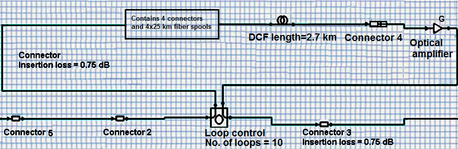 | Figure 1. Designed optical link |
2.3. Design of the Receiver Block
- The receiver is composed of two parts: a demultiplexer with 32- output channels and insertion loss of 5dB, and a photodiode for each output connected to the eye-diagram analyzer. PIN photodiode was chosen as the photodetector, because of its lower cost and sensitivity to the shot noise in comparison to avalanche photodiodes (APDs). These types of photodiodes need reverse bias to operate, so they provide better performance for wide bandwidth and high dynamic range applications [13]. For each channel of the demultiplexer, a PIN photodiode with insertion loss of 3 dB and dark current of 10 nA was used to change the received signals into the electrical equivalents. An eye-diagram analyzer has been used to analyze the detected signals of each channel.
3. Response of the Designed Optical Network
- The eye-diagram of the received signal is illustrated in Fig.2, where the Q-factor and minimum BER are 20.7 dB and 7.6×10-95, respectively, which complies with an error-free optical network having a minimum bit error rate [14].
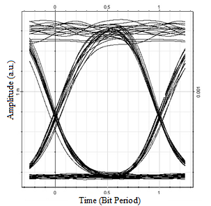 | Figure 2. Eye-diagram of the received signal from the channel 1 |
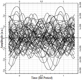
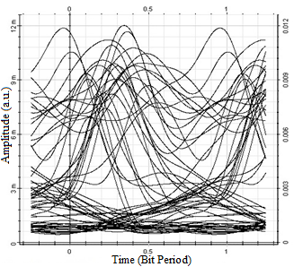 | Figure 3. The eye-diagram of the received signal from 1000 km transmission link without using a DCF |
 | Figure 4. The eye-diagram of the received signal over the 1000 km link without optical amplifier |
4. Conclusions
- In the current study, we have simulated a 160 Gb/s DWDM optical network by using NRZ encoding format. Post-DCF and optical amplifiers have been employed to compensate the dispersion and power loss of the optical signals, respectively, caused by signal transmission through a 1000 km non-zero dispersion shifted fiber (NZDSF). We have designed 10-spans, each containing 4×25 km fiber spools which were connected to 2.7 km of DCF with dispersion coefficient of -147 ps/nm.km and an EDFA with a gain of 14 dB. By assuming the power of transmitter 0 dBm, the obtained BER and Q-factor are7.6×10-95 and 20.7dB, respectively. Removing DCF and EDFA from the network, the simulations have shown a sharp quality degradation in the received signals.The designed optical network for a distance of 1000 km may be redesigned for longer distances by increasing the amplifier gain. Also, by reducing the channel spacing may lead to a greater bit rates. Any changes in the transmission distance requires a re-evaluation of all parameters, affecting on the quality of the optical network.This study was repeated by using direct modulation and the results showed a better performance of the network. The minimum BER and the Q-factor of the received signal from channel 1 are obtained as 21.25 and 1.3×10-100, respectively. It is shown that there is no difference between the voltages and OSNR of the received signals from 32-channels in both the methods. Also, it has been found that by considering the cost and complexity of implementation of external modulation, direct modulation may be a better choice for long-haul optical fiber systems.