-
Paper Information
- Paper Submission
-
Journal Information
- About This Journal
- Editorial Board
- Current Issue
- Archive
- Author Guidelines
- Contact Us
International Journal of Optics and Applications
p-ISSN: 2168-5053 e-ISSN: 2168-5061
2016; 6(1): 13-19
doi:10.5923/j.optics.20160601.03

Using Cellophane Sheet to Encrypt Information on Digital Holograms
 Abstract
 Reference
 Full-Text PDF
 Full-text HTML
Alex K. Muthumbi1, Geoffrey K. Rurimo2, Calvine F. Ominde1
1Department of Physics, Jomo Kenyatta University of Agriculture and Technology, Nairobi, Kenya
2Department of Physics, Multimedia University of Kenya, Nairobi, Kenya
Correspondence to: Alex K. Muthumbi, Department of Physics, Jomo Kenyatta University of Agriculture and Technology, Nairobi, Kenya.
| Email: |  |
Copyright © 2016 Scientific & Academic Publishing. All Rights Reserved.
This work is licensed under the Creative Commons Attribution International License (CC BY).
http://creativecommons.org/licenses/by/4.0/

This paper reports the application of cellophane sheet to encrypt and decrypt both the phase and amplitude information in digital holograms using the double random phase encoding in Fresnel domain. In a Mach-Zehnder interferometer setup, an object and two cellophane sheets were placed on one arm of the interferometer, while a quarter wave plate and a half wave plate were placed along the reference arm for phase shifting. Digital holograms were recorded using a CCD camera, and their numerical reconstruction and propagation performed using MATLAB R2015a software. The results show that cellophane sheet can be used to encrypt and decrypt phase and amplitude information in digital holograms. When using the correct keys at the correct distance, the peak signal to noise ratio (PSNR) and structural similarity index metric (SSIM) are much higher than at other instances, meaning better reconstructed images. The percentage error in SSIM when cellophane is used to encrypt and decrypt information at the correct distance was found to be 15.32%when using correct key at correct distance compared to17.0% and 16.13% errors when using wrong key and wrong distance, respectively.
Keywords: Digital holograms, Double random phase encoding, Cellophane
Cite this paper: Alex K. Muthumbi, Geoffrey K. Rurimo, Calvine F. Ominde, Using Cellophane Sheet to Encrypt Information on Digital Holograms, International Journal of Optics and Applications, Vol. 6 No. 1, 2016, pp. 13-19. doi: 10.5923/j.optics.20160601.03.
Article Outline
1. Introduction
- Since its inception two decades ago, digital holography has been widely investigated and applied in many areas like metrology [1], security [2], microscopy [3], particle analysis [4], three-dimensional display [5], to name but a few. In digital holography, the interfering coherent object and reference beams are recorded using a CCD camera, followed by numerical reconstruction and propagation. During the recording of a digital hologram, there exists the zero-order term and the real and virtual images (twin image) due to diffraction. An off-axis configuration can be used while recording digital holograms to avoid the problem of the zero order term [6]. However, the resolution of the image is reduced as a result of discarding the zero order term and the real image. Consequently, the on-axis digital hologram recording configuration is preferred in order to maintain a high quality of the reconstructed hologram. In this configuration, the phase-shifting technique is employed to remove the zero order and solve the problem of twin image [7]. In this process, multiple holograms are recorded, and the complex field is calculated which is free of the twin image and the zero-order term. By using this process, the quality of the reconstructed hologram is preserved.Since Réfrégier and Javidi [8] proposed double random phase encoding (DRPE), securing information by optical technologies have been widely used. In their original paper, DRPE was done in the Fourier domain, and phase masks were used to introduce the phase as the only key in their recording configuration. Different domains have been demonstrated that incorporate DRPE, including Fresnel domain [9], Fractional Fourier transform domain [10], gyrator transform [11] among others. In the Fresnel domain, geometrical parameters such as the axial distances and wavelength are also used as security keys, besides the use of the phase masks. This means that the three-dimensional positions of the masks must also be known to correctly decrypt the holograms. Algorithms such as known-plaintext, chosen-plaintext and chosen-ciphertext which seeks to decipher the encrypted image have shown the vulnerability of DRPE. However, by varying the phase of the phase masks for each input image, one can fully secure the encrypted data from attacks [12]. With this approach, DRPE is believed to be highly secure.Cellophane is a thin, flexible and transparent organic polymeric material made from wood pulp. It is widely used as wrappers and in packaging food and merchandize since it is impermeable to gases, grease, or bacteria. It is fabricated by extruding a viscose solution through a dye into a bath of dilute sulfuric acid and sodium sulfate. As a result of differential strains between the longitudinal and transverse directions of the protrusion, the refractive index of the light polarized parallel to the slit is smaller than that of the light polarized perpendicular to the slit. This means the phase velocity of the light wave polarized parallel to the slit (fast axis) is faster than that of the wave polarized perpendicular to the slit (slow axis). Thus, optically the cellophane sheet is birefringent and the directions of fast and slow axes are perpendicular to each other [13], and can thus be used as a half wave plate. A cellophane sheet is a good choice of a birefringent material since its fibers are oriented in a particular direction. It is approximately 24μm thick and can be cut to almost any desirable size with ease. The sheet has been used to study effects on polarized light [14], fabricate a complementary cellophane optic gate for 3D iPad display [15], converting a laptop screen into a three-dimensional screen [16], and conversion of a linearly polarized Gaussian beam to either radially or azimuthally polarized beams [17]. In [18], the phase shift induced by cellophane sheet was calculated to be 0.98π.In DRPE, phase masks are used to randomize the information passing through them. Usually, commercially available phase masks like the liquid-crystal spatial light modulator are used in encoding amplitude and phase of object beam [8-10]. Variable polarization phase masks have also been used to manipulate the polarization state of a beam, and this idea used in encrypting information [19-21]. Cellophane sheet which is birefringent has been used to modify the polarization state of a linearly polarized incident beam [17, 18]. It has also been shown to introduce a phase change on a linearly polarized incident beam [14, 18]. Using cellophane sheet as a phase mask in DPRE would be attractive as it is very cheap and readily available compared to commercially available phase masks. It also offers the advantage of flexibility and ease of use in optical setups. Additionally, its birefringent property can be used in encrypting information into a beam by modifying the polarization of the beam. To the best of our knowledge, cellophane sheet has not been used as a phase mask in DPRE. In this paper, we report the results of using cellophane sheet as phase masks in encrypting information on digital holograms. The orientation of the two cellophane sheets used in this experiment was along their fast axes, and no rotation of the sheets to induce polarization changes was done.
1.1. Digital Holography
- The development of CCD technology in recent years has contributed to the growth of digital holography. Digital holograms are created by interfering coherent object and reference beams and the resulting pattern recorded by a CCD camera and processed by computational methods to obtain a holographic image [22]. The recorded holograms, like conventional holograms, contain both the amplitude and phase information about the object. The object and reference waves can be described mathematically as
 | (1) |
 | (2) |
 and
and  are the real amplitudes for the object and reference waves respectively,
  and
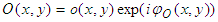
and  are the phases of object and reference waves respectively.The two waves interfere at the surface of the CCD camera, and the resulting intensity is described by
 | (3) |
 denotes the complex conjugate. The first two terms on the right of equation (3) constitute the undiffracted wave passing through the medium (zero-order term). The third term constitutes the virtual image, while the fourth term represents the conjugate image (twin image). For on-axis recording setup, all these three terms are superimposed at the recording plane, resulting in noise. To remove the zero-order terms and the twin image, phase shifting technique is usually employed. This process involves recording at least 3 holograms with mutual phase shifts between them. The complex field, free of the zero order and the twin image can then be derived from these holograms [7].The amplitude transmission
  of the recording medium is proportional to intensity
  and is given by
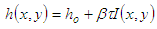 | (4) |
 is a constant,
  is the exposure time and
  the amplitude of transmission for unexposed plate. In digital holography,
  is ignored. During holographic reconstruction, the hologram diffracts the reconstructing light wave
  giving rise to a reconstructed wavefield
  described by the Fresnel-Kirchhoff’s integral [22] given as equation 5:
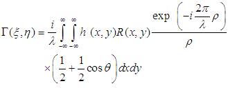 | (5) |
 .
.  is the hologram function and
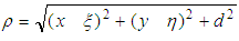
  is the distance between a point in the hologram plane and a point in the reconstruction plane, as shown in figure 1. Angle
  is described in figure 1.
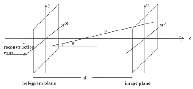 | Figure 1. Coordinate system |
 both amplitude and phase can be calculated.
1.2. Double Random Phase Encoding
- In double random phase encoding, two statistically independent phase masks are used to convert an input image to stationary white noise. The first phase mask converts the signal into noise, but not stationary, while the second phase mask not only maintains the white noise but also makes it stationary. This has been shown using an autocorrelation function [8]. Let
 define the image to be encoded having a size of
  pixels. Its normalized value has a maximum value of one. The spatial coordinates are denoted by
  and
and  denotes the coordinates in the Fourier domain. Let
  and
and  be two functions defining randomly chosen phase masks and
  be the double phase encoded image obtained after the two phase masks. The encoded image
  is given by
 | (6) |
 is the impulse response of the phase mask function
  and
and  stands for convolution. To decode the double-phase-encoded image
  , its Fourier transform is multiplied by
 , then taking the inverse Fourier transform of the result produces
  To recover
  the function
  is multiplied by
2. Experimental Setup
- Digital holograms were recorded using the Mach-Zehnder setup shown in figure 2.
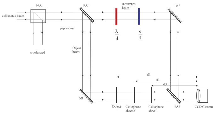 | Figure 2. Encryption of digital holograms by double random phase encoding. PBS – polarizing beam splitter, BS 1 and BS 2 are beam splitters, M1 and M2 are reflecting mirrors |
3. Results
3.1. Simulated Results
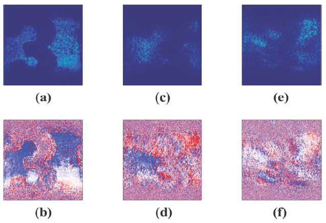
- Figure (3a) and 3(b) shows the amplitude and the phase of the reconstructed hologram of the object, before DRPE was performed. Simulation was done for DRPE to get the encrypted hologram. In the decryption process, knowledge of the phase masks used and the distances they were placed during recording are necessary. Figure 3c and 3d, shows the decrypted amplitude and phase when the correct phase masks and distances are used. Any changes in either the phase masks used and/or in the distances results in failure to successfully decrypt the hologram, as can be seen in figure 3e and 3f, where the phase masks are wrong but at correct distances, and figure 3g and 3h, where the distances are wrong but using correct phase masks. Hence, to successfully decrypt the digital hologram, the knowledge of the phase masks used and their distances from the recording plane must be known.
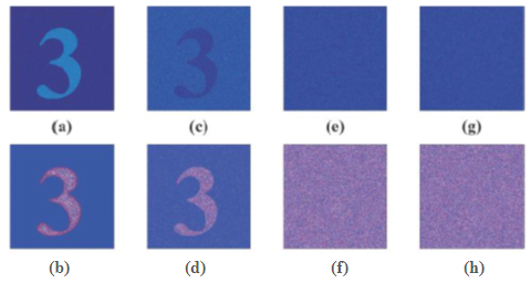 | Figure 3. (a) Amplitude and (b) phase of the object. (c) Amplitude and (d) phase of decrypted hologram, using the correct keys and at correct distances. (e) Amplitude and (f) phase of decrypted hologram when using wrong keys at correct distance. (g) Amplitude and (h) phase of decrypted hologram at wrong distance with correct key |
3.2. Experimental Results
- In figure 4, we show the reconstructed amplitude and phase of the object hologram, before encryption was done. These would be used for comparison with the decrypted holograms later. The phase profile in figure 4b has a precision of a fraction of the optical wavelength, and reveals nanometric variations of the surface of the object that the amplitude image in figure 4a does not show. Since the average pixel value M, given by equation
 | (7) |
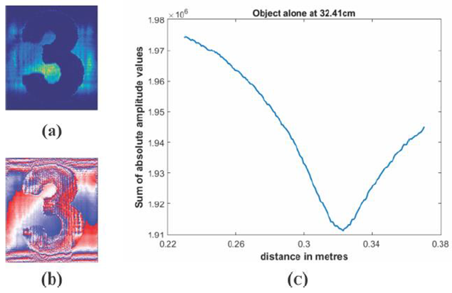 | Figure 4. (a) Amplitude, (b) phase and (c) graph of M-values against distance, for object alone |
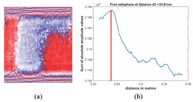 | Figure 5. (a) first key, (b) graph of M-values against distance |
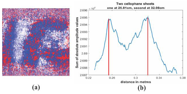 | Figure 6. (a) Second key, (b) graph of M-values against distance |
 | Figure 7. (c) amplitude and (d) phase decrypted at correct distance using correct keys. Decrypted hologram’s (e) amplitude and (f) phase using wrong keys, but at correct distances. (g) Amplitude and (h) phase using wrong distances but correct keys |
3.3. Analysis
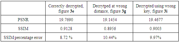
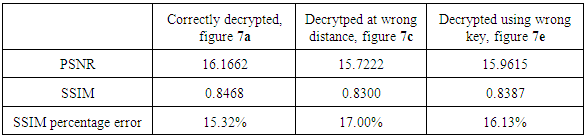
- While the final arbiter of quality of images is human eye, there exist some objective measures of quality, peak signal-to-noise ratio (PSNR) and structural similarity index measure (SSIM). PSNR is simple to calculate, but sometimes it does not align well with perceived quality by humans, while SSIM is based in the principle that the human visual system is good for extracting information based on structure. In these measurements, one uses a distortion-free image (reference image) for comparison with the image whose quality is to be measured. The maximum (from comparing the reference image with itself) PSNR is infinity, while the maximum SSIM is one. Using figure 3a and 4a as reference images for simulation and experimental data respectively, the PSNR and SSIM for the different amplitudes at different conditions were tabulated. Table 1 shows the simulated results, while table 2 shows the experimental data. From both the simulated and experimental data, it is observed that the PSNR values are higher for the correctly decrypted images than when either or both the keys or the distances are wrong. This corresponds to a much better quality of the image when correctly decrypted than when improperly decrypted. The SSIM values are also higher for the correctly decrypted images than the other two cases. Since the maximum SSIM value is one, a higher value of SSIM corresponds to a better quality of the image than a lower value. The percentage error in SSIM is also calculated. From the two tables, we see that the percentage error from simulation of the SSIM value is smaller than the experimental percentage error values. This stems from the fact that the beams used during the experiment may pick up some noise during propagation that the simulated beams do not acquire.
|
|
3.4. Discussion
- In DRPE, two phase masks are used to encrypt information on digital holograms, and only these phase masks can be used to decrypt the holograms recorded. Experimentally, our DRPE setup was able to show that only the information of the two cellophane sheets used in the experimental setup can be used to decrypt the recorded holograms.Experimental setups with DRPE implemented in the Fresnel domain use the distances from the two phase masks and the CCD camera, plus the phase obtained from these phase masks as keys in the encryption and decryption process. In our experiment, the distances from the two cellophane sheet used and the CCD camera, plus the phase information obtained from the sheets were used as the keys. The results obtained show that only the use of the correct distances of the cellophane sheet and the CCD camera and correct phases from the two cellophane sheet used in the experiment can be used to correctly decrypt the holograms recorded. Changing either the distance from the cellophane sheet used and the CCD camera or the phase obtained from the two cellophane sheets leads to incorrect decryption. The peak signal to noise ratio (PSNR) and the structural similarity index measure (SSIM) metrics are used as a measure of the success of the decrypting process. In our results, we used the peak signal to noise ratio (PSNR) and the structural similarity index measure (SSIM) rather than the signal to noise ratio (SNR). This is due to the fact that the human eye distinguishes easily scenarios having different light intensities rather than signals embedded in noise; hence the use of PSNR instead of SNR. This measure of quality has been used by other publishers. The quality of the results obtained when using cellophane sheet is lower than those obtained by other researchers. This can be attributed to the cellophane sheets not purposely designed for optical experiments in which the surface quality degrades the results. However, the proof of concept and the general trend of the results obtained in our experiment compares very well with those obtained by other researchers.
4. Conclusions
- In DRPE, two phase masks are used to encrypt information on digital holograms, and only these phase masks can be used to decrypt the holograms recorded. Experimentally, our DRPE setup in the Fresnel domain was able to show that only the information of the two cellophane sheets used in the recording of digital holograms can be used to decrypt the recorded holograms. The distances from the two cellophane sheets and the CCD camera, plus the phase obtained from these cellophane sheets are used as keys in the encryption and decryption processes. The results obtained show that only the use of the correct distances of the cellophane sheet and the CCD camera and correct phases from the two cellophane sheet used in the experiment can be used to correctly decrypt the holograms recorded. Changing either the distance from the cellophane sheet used and the CCD camera or the phase obtained from the two cellophane sheets leads to incorrect decryption.Both visual and numerical analysis results show that cellophane can be used in encryption and decryption of information on digital holograms. The correctly decrypted holograms enable one to recognize the information encrypted in the holograms. Use of either wrong key or wrong distance does not recover the encrypted information. This demonstrates the high security of information encrypted using cellophane. Higher PSNR and SSIM values mean the images compared are closely similar than when lower values are obtained. Hence, the amplitude image of correctly decrypted hologram is closely similar to the amplitude image of the object hologram without encryption than the decrypted amplitude images using wrong keys and/or wrong distance. This leads us to conclude that cellophane sheet can be used to securely encrypt and decrypt information in digital holograms. In these experiments, the orientation of the two cellophane sheets used was along their lengths. Since cellophane sheet is known to change the polarization direction of polarized light when rotated, further work on the effect of rotating the cellophane sheets on encrypting and decrypting digital holograms can be conducted.
ACKNOWLEDGEMENTS
- This research was conducted at Jomo Kenyatta University of Agriculture and Technology’s optics and laser’s laboratory. It was funded by Government of Kenya through the National Council for Science, Technology and Innovation (NACOSTI), grant number NACOSTI/RCD/ ST&I 6TH CALL MSc/143. The support is gratefully acknowledged.