Ahmad K. Ahmad, Mohammed F. Majeed
Physics Department, College of Science AL-Nahrain University, Bagdad, Iraq
Correspondence to: Mohammed F. Majeed, Physics Department, College of Science AL-Nahrain University, Bagdad, Iraq.
| Email: |  |
Copyright © 2016 Scientific & Academic Publishing. All Rights Reserved.
This work is licensed under the Creative Commons Attribution International License (CC BY).
http://creativecommons.org/licenses/by/4.0/

Abstract
In this paperwe present a method for calculating the acoustic velocity and acousto-optic figure of merit (AOFM). The AOFM as a function of material's refractive index, density, effective elasto-optic coefficient and the velocity of the acoustic wave in the material, are also investigated. By examining the directional dependent velocity, elasto-optic coefficients, and refractive index, the (AOFM) can be calculated and plotted in all directions revealing the optimal crystal orientation to maximize coupling between the optical and acoustic waves. We applied our method to four Oxide crystals such as (Lithium Niobate (LiNbO3), Lead Molybdate (PbMoO4),Titanium Dioxide (TiO2) and Zinc Oxide (ZnO)). The Wolfram Mathematica software are used to obtain the results. The results are shown that the AOFM is directional depend on acoustic wave propagation and Lead Molybdate (PbMoO4) have the highest figure of merit which is equal to [20.96910-15 (s3/Kg)] this value achieved in longitudinal acoustic wave propagation.
Keywords:
Acousto-optic, Figure of Merit, Effective elasto-optic, Acousto-optic Modulator, Oxide crystals
Cite this paper: Ahmad K. Ahmad, Mohammed F. Majeed, Calculation of Acousto-Optic Figure of Merit for Some of Oxide Crystals, International Journal of Optics and Applications, Vol. 6 No. 1, 2016, pp. 1-6. doi: 10.5923/j.optics.20160601.01.
1. Introduction
Acousto-Optic (AO) devices are widely used in image processing, signal processing, laser spectroscopy, optoelectronics, medicine, etc. [1-3]. These devices control characteristics of a laser beam diffracted on gratings generated by ultrasound in crystals. Intensity of diffracted light depend on acoustic driving power and AO figure of merit (AOFM)  The acousto-optic figure of merit (AOFM) is a measure of the suitability of a material to modulate the diffraction intensity. The refractive index, effective photoelastic coefficient, density and acoustic wave velocity are all used in this calculation but it is the refractive index and acoustic wave velocity that are the dominant factors. The slower the acoustic and optical waves in the material the more interaction possible [4]. There are other figures of merit related to acousto-optic devices however the (AOFM) referred in Eq. (1) is used primarily for gauging the power efficiency of AO materials and is not for example used to determine the usable bandwidth of the device [5].
 | (1) |
where  denotes the refractive index,
  the density of material and
  the acoustic velocity.
2. AO Materials Coefficients
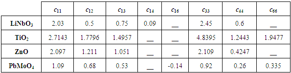
The necessary parameters for calculating the figure of merit for four common materials are listed in Tables 1 through 4. In Table 1 all data measurements at 0.633 µm, except for TiO2 at 0.514 µm. To calculate the elastic wave velocity in linear elastic materials (such as TiO2 and PbMoO4) only the elastic stiffness coefficients  and the density
  are needed however, for piezoelectric materials consideration of the piezoelectric coupling coefficients
  and the permittivity
  are also required [6]. Typically, AO materials are chosen based on both their availability. Some of the most commonly used materials are Lithium Niobate (LiNbO3), Lithium Tantalate (LiTaO3), Lead Molybdate (PbMoO4). Paratellurite (TeO2), fused silica (SiO2), Rutile (TiO2), Zinc Oxide (ZnO), and Gallium Arsenide (GaAs). Many other materials are also used that have high figures of merit. This paper will consider Lithium niobate, Rutile, Zinc Oxide (Wurtzite) and Lead Molybdate due to the availability of data. The developed capability can be readily extended to advanced materials upon the availability of needed physical parameters [7].
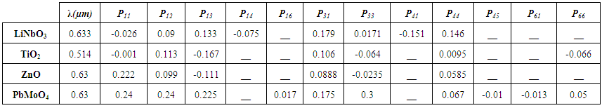 | Table 1. Elasto-optic coefficients – unitless [4, 8, 9] |
3. Calculation Method
The properties of the directionally dependent materials are more readily plotted using the spherical coordinate system. Fig.1 show that the direction  which represent the radius, i.e. length of
  vector, in spherical coordinate relative to Cartesian system of
 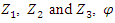 is angle from
  axis on the
  plane and the angle theta
  from
from  axis [11].
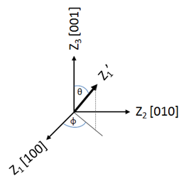 | Figure 1. Spherical Coordinates |
The elasto-optic effect is a 4th rank tensor property that can be fully described with a 6x6 matrix using Voigt notation. The 6x6  is used to analyze longitudinal directional dependence of effective elasto-optic coefficient
  about an arbitrary direction
  Note
Note  represent rotation direction cosine matrix. While other effects such as the refractive index can be evaluated by way of the 3x3 transformation
  Where
Where  represent direction cosine matrix. Both the
  and
and  matrices are made up of the directional cosine elements as defined below [12].
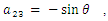
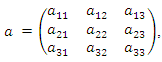 where
where ,
, 
 by setting the matrix elements one can get
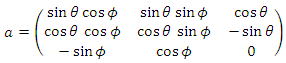
Table 2. Elastic coefficients – units of 1011 (N/m2) [8]
 |
| |
|
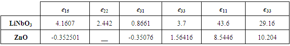
Table 3. Piezoelectric coupling coefficients – units of (C/m2) and Permittivity coefficients – unit less [4, 10]
 |
| |
|
Rotation matrix  is given by
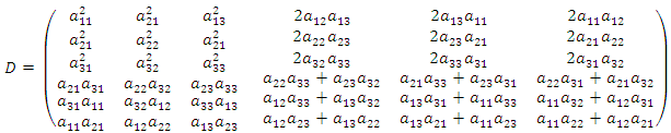
3.1. Effective Elasto-Optic Coefficient
The value of effective elasto-optic coefficient  can be calculated using Eq. (2), multiplying
  matrix by the material matrix
  (whose components are defined by its crystallographic axis) and again by the transpose of the
  matrix and extracting the top left element [1,1].
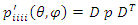 | (2) |
In the following text the direction of tensile strain is designated as  direction and the physical meaning of the
  is the amplitude of longitudinal effective elasto-optic coefficient. A plot of
  is a graphical representation of its directional dependence [12].
3.2. Refractive Index
The refractive index (represented as a 3x3 matrix) is found in a similar manner as to the effective elasto-optic but now using the  matrix [12].
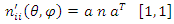 | (3) |
where  matrix is given by the following form
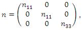 where the
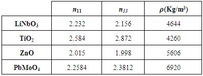
  matrix element value given in the Table 4.
Table 4. Refractive index coefficients and density – density in units of (kg/m3) [4]
 |
| |
|
3.3. Acoustic Velocity
The sound velocity in a homogeneous anisotropic medium has multiple solutions for any given wave propagation orientation and thus requires a different method of evaluation as compared to the aforementioned elasto-optic and refractive index. Typically, there is one longitudinal wave with vibration direction parallel to propagation and two transversal shear waves [4]. In a non-center-symmetric material each of the wave components may be also accompanied by oscillating polarizations coupled through piezoelectric effect. Acousto-optic materials can be either linear elastic or piezoelectric. The velocity of linear elastic materials is determined by orientation, density, and the elastic constants. Piezoelectric materials however must also consider the piezoelectric coupling matrix and permittivity [13]. The modified Christoffel equation Eq. (4) used to find the wave velocities is shown below. The tensor  represents the linear elastic portion and is a product of the inverse density
  the elastic tensor
  and the directional cosines
  tensors and constant
  represent the velocity adjustment resultant from the piezoelectric contribution.
  is the piezoelectric coupling tenor and
  denote the permittivity. It is important to note that
  here is not the relative permittivity but rather the absolute permittivity
  in F/m, the velocity is
  is the Kronecker delta
  and zero otherwise), and
  is the amplitude of the lattice displacement in k-direction [4].
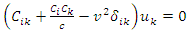 | (4) |
 | (5) |
 | (6) |
 | (7) |
 | (8) |
 | (9) |
 | (10) |
For clarity these tensor components for the general case are written explicitly below | (11) |
To illustrate the matrix method, we write out  The tenser stiffness
  are converted to matrix stiffnesses
  by using Voigt notation, where
 | (12) |
 | (13) |
The other four Christoffel coefficients  are evaluated in a similar way. The other parameter of Christoffel equation
  can write as below form
  | (14) |
 | (15) |
 | (16) |
 | (17) |
The calculation method is more easily seen by converting the Christoffel Equation to matrix form and inserting the above relations to form the matrix  below. The velocities are now simply the square root of the eigenvalues of the matrix
  and the corresponding wave polarizations are from the eigenvectors of
  .
. 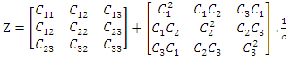 | (18) |
3.4. Figure of Merit
The valve of Figure of Merit (M2) can be calculated by combining the effects of density, effective elasto-optic coefficient, acoustic velocity and refractive index as shown as Eq. (19).  is plotted as a function of theta and phi,
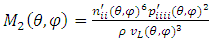 | (19) |
4. Results and Discussion
4.1. Acoustic Velocity
All the calculation according to method that described in previous section have been performed using the data specified in Tables 1 through 4. The date for permittivity in the table 3 are taken from Ref [10] which represent the data from material library in Comsol Multiphysics 5.0. The results have been studied for four types of materials which are: Lithium Niobate (LiNbO3), Lead Molybdate (PbMoO4), Titanium Dioxide (TiO2) and Zinc Oxide (ZnO). Figure (2) show that acoustic velocity in quasi-Longitudinal mode for different materials. from this figure it’s clear that Titanium Dioxide crystal have highest value of acoustic velocity that equal to 10079.5 m/sec this value achieved in Longitudinal acoustic wave propagation mode, while the Lead Molybdate crystal have the lowest value of acoustic velocity that equal to 4834.6 m/sec. this value will give a good indication that the Lead Molybdate crystal have highest figure of merit. 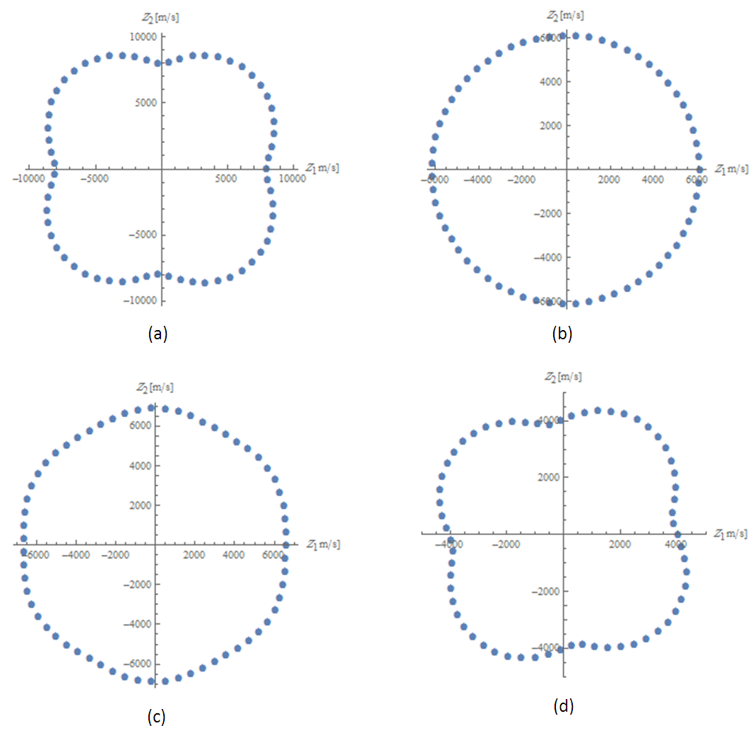 | Figure 2. Acoustic velocity propagate quasi-Longitudinal mode for selected crystals: (a) TiO2, (b) ZnO, (c) LiNbO3, (d) PbMoO4 |
4.2. Figure of Merit
Mathematica software was used to provide a three dimensional visualization of the Acousto-optic effect for a crystal of any point group symmetry. One can select the point group and then from a library of material data associated with that group. Figure of Merit  can be calculated by using Eq. (19). To demonstrate the impact of anisotropy on the Figure of Merit value, below we present several example material representing different crystal systems. The dependences of the Figure of Merit on the direction of acoustic wave propagation calculated at different orientations are shown in Fig.3.
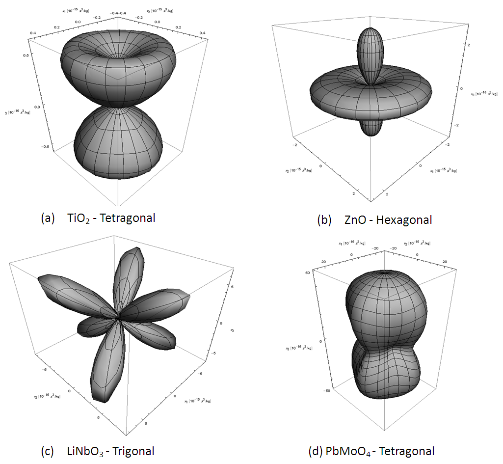 | Figure 3. Dependence of figure of merit (M2) on direction of acoustic wave propagation calculated for several materials representing different crystal system: (a) TiO2, (b) ZnO, (c) LiNbO3, (d) PbMoO4. All results are shown in terms of  |
The maximum Figure of Merit value for TiO2 is equal to  This value is achieved in the case of AO interaction with the longitudinal acoustic wave propagating at the angle (
 and
and 
 For, ZnO the maximum value of Figure of Merit is equal to
  This value is achieved in the longitudinal acoustic wave propagating at the angle
  is any value between (0-360) deg). While for LiNbO3, the maximum Figure of Merit value is equal to
  This value is achieved in the longitudinal acoustic wave propagating at the angle
  Finally, for PbMoO4 have the highest Figure of Merit is equal to
 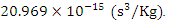 This value is achieved in the longitudinal acoustic wave propagating at the angle
  The figure of merit is typically used to compare or gauge the effectiveness of AO materials however, it can also be used to determine the ideal material orientation for maximum acoustic/optic coupling. The elasto-optic matrix is certainly the dominant factor in determining ideal coupling; however as can be seen in the figure of merit calculation the refractive index and the velocity are directionally dependent they can also have a significant impact on coupling. The three dimensional representation Fig.3 can be used to effectively determine the maximum coupling orientation. Using the information the ideal material orientation have been determined for each of the material and summarized in Table (6). The values are listed for
  and
and 
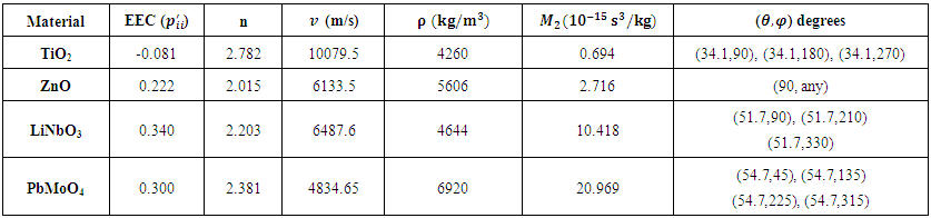 | Table 6. Maximum Figure of Merit for each material with associated property maximum in the same direction |
To test the results of our analysis, we make a comparison with the available literature data. Some of our results agree well with literature data. The acousto-optic figure merit for LiNbO3 crystal is equal to 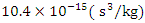 according to Ref. [14], while the authors of Ref. [15] have reported it to be
 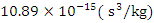 . The calculation parameter obtained for the acousto-optic figure of merit in LiNbO3 crystal demonstrating good agreement and thus positive verification of the methodology developed.
5. Conclusions
In this present work a fast and precise method have proposed for calculating the acousto-optic figure of merit. The elasto-optic coefficient and acousto-optic figure of merit can be obtained for any crystal class, and the maximum direction of interaction is calculated. The results are shown that the acousto-optic figure of merit is directional depend on acoustic wave propagation and have found that the highest acousto-optic figure of merit value for Lead Molybdate (PbMoO4) is equal to  this value achieved in the longitudinal acoustic wave propagation. The methodology developed in this work provide positive verification through the good agreement with the result of Acousto-Optic Figure of merit for LiNbO3 known from literatures.
References
| [1] | I. Chang, "Acoustooptic devices and applications," IEEE transactions on sonics and ultrasonics, vol. 23, p. p2, 1976. |
| [2] | D. R. Pape, A. P. Goutzoulis, and S. V. Kulakov, Design and fabrication of acousto-optic devices: M. Dekker, 1994. |
| [3] | J. Xu and R. Stroud, Acousto-optic devices: principles, design, and applications vol. 12: Wiley-Interscience, 1992. |
| [4] | R. E. Newnham, Properties of Materials: Anisotropy, Symmetry, Structure: Anisotropy, Symmetry, Structure: Oxford University Press, 2005. |
| [5] | G. F. Marshall and G. E. Stutz, Handbook of optical and laser scanning: CRC Press, 2011. |
| [6] | P. P. Banerjee, "Meta-acousto-optics: the interaction of light and sound in an acoustic negative index medium," in SPIE Nano Science+ Engineering, 2010, pp. 77540R-77540R-7. |
| [7] | I. Chang, "Selection of materials for acousto-optic devices," Optical Engineering, vol. 24, pp. 241132-241132-, 1985. |
| [8] | M. J. Weber, Handbook of optical materials vol. 19: CRC press, 2002. |
| [9] | M. Bass, Handbook of optics. Vol. 2, Devices, measurements, and properties: McGraw-Hill, 1994. |
| [10] | M. Burlington, "COMSOL Multiphysics, Materials Database Version 5.0,": COMSOL, Inc., 2014. |
| [11] | O. Mys, M. Kostyrko, M. Smyk, O. Krupych, and R. Vlokh, "Anisotropy of acousto-optic figure of merit in optically isotropic media," Applied optics, vol. 53, pp. 4616-4627, 2014. |
| [12] | R. McIntosh, "Piezoelectric resonance enhanced microwave and optoelectronic interactive devices," 3563204 Ph.D., The University of Texas at San Antonio, Ann Arbor, 2013. |
| [13] | O. Mys, M. Kostyrko, O. Krupych, and R. Vlokh, "Anisotropy of the acousto-optic figure of merit for LiNbO 3 crystals: isotropic diffraction," Applied Optics, vol. 54, pp. 8176-8186, 2015. |
| [14] | О. Buryy, А. Andrushchak, O. Kushnir, S. Ubizskii, D. Vynnyk, O. Yurkevych, et al., "Method of extreme surfaces for optimizing geometry of acousto-optic interactions in crystalline materials: Example of LiNbO3 crystals," Journal of Applied Physics, vol. 113, p. 083103, 2013. |
| [15] | J. B. Pfeiffer and K. H. Wagner, "Acousto-optic Figure of Merit Search," Physics Procedia, vol. 70, pp. 762-765, 2015. |

 Abstract
 Reference
 Full-Text PDF
 Full-text HTML