Sairam Kvssss
Professor (E&CE) Nmamit, Nitte
Correspondence to: Sairam Kvssss, Professor (E&CE) Nmamit, Nitte.
| Email: |  |
Copyright © 2015 Scientific & Academic Publishing. All Rights Reserved.
This work is licensed under the Creative Commons Attribution International License (CC BY).
http://creativecommons.org/licenses/by/4.0/

Abstract
Optical communication is an advanced communication in which the data, voice and video services are integrated. The recent trends of optical communication are mainly deals with network transmission using fiber as a media in terms of networking, switching and routing. This paper projects on implementing fiber optic survivable techniques with Digital Signal Levels and Optical Carriers by using sender and receiver (point to point) approach.
Keywords:
Survivability, FOST, FORT, Point to point
Cite this paper: Sairam Kvssss, Implementation of Fiber Optic Layers by Using Point–to–Point Approach, International Journal of Optics and Applications, Vol. 5 No. 6, 2015, pp. 181-186. doi: 10.5923/j.optics.20150506.01.
1. Introduction
The optical communication is referred to as guided media is as shown in figure 1. The optical networks are classified with respect to users and systems i.e., 1:1, 1: N, and N:1 and N:N. The optical networks will also provide the quality of service i.e., point to point and/or multipoint communication. Hence the Optical Communication System (OCS) is given by 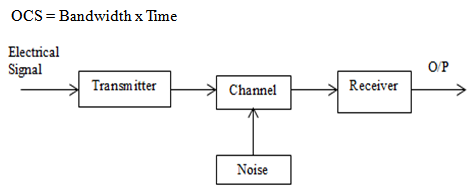 | Figure 1. Optical Communication Block Diagram |
The bandwidth is defined as the difference between the higher data rate to the lower data rate. These data rates are measured in bits per second. Hence the normal conversion in optical networks is taken by 1Hz= 2bps. The network estimation is measured by its demand distribution which is represented in figure 2.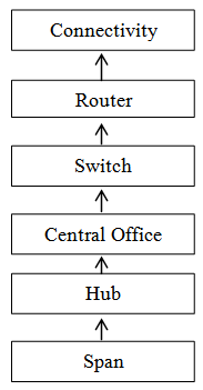 | Figure 2. Optical Communication Block Diagram |
2. Survivable Techniques Implementation
In optical communication networks survivability resolves the effective throughput through a process during and after a failure. First method the network connectivity should be obtained through the path (link) connectivity. Next Data Connectivity should be established through the path. Hence the Digital Cross Connectivity is estimated with DXC = Link connectivity + Data ConnectivitySecond method: Further the Digital cross connectivity can be enhanced through the Digital signal levels along with the optical carriers (OC) in order to obtain the Optical Cross Connectivity. Therefore Optical Cross Connectivity (OXC) is obtained by multiplying the DXC with Data Signals.The evaluation of optical network connectivity’s is further evaluated through the different types of connectivity’s and also their architectures which are distributed through two different layers viz. physical layer and logical layer as shown in figure 3.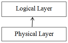 | Figure 3. Optical Communication Block Diagram |
Fiber optic physical layer connectivity is as shown in figure 4.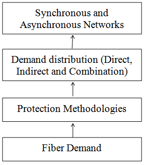 | Figure 4. Physical Layer Connectivity |
The parameters are 1) Fiber demand: It is the demand which is expressed as the number of nodes (users) vs. the capacity. 2) Protection methodologies: It can be expressed as the link protection, path protection and network protection in order to obtain maximum protection through alternative paths. It is given by Survivability ratio = (Total number of demands after failure)/ (Total number of demands before failure)3) Demand distribution: It is defined as the path associated either direct, indirect and quasi (combination of both direct and indirect). In direct path transmission the source node will transmit the information directly to the reception node. In the indirect transmission the information is divided into number of parcel list (splitting into number of parts). In quasi the information can be received in both direct and indirect transmission modes.4) Synchronous and Asynchronous: It enables the tools for real time communications in order to support the high data transfer rate from sender to the receiver (Kbps to Tbps). In asynchronous mode data transfer rate will be slow as the sender provides a signal before starting of each data.The Logical layer connectivity is as shown in figure 5. The Logical layer is given by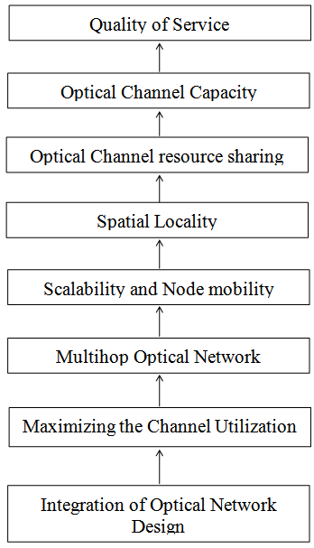 | Figure 5. Logical Layer Connectivity |
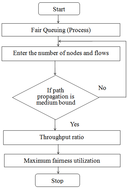
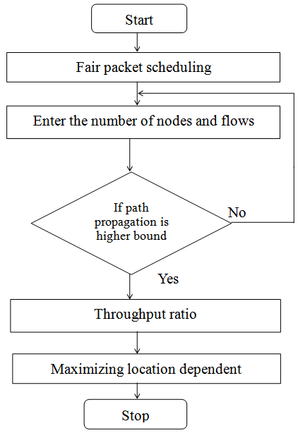
1) Integration of Optical Network Design Issues: It is expressed in terms of node graph and flow graph.2) Maximizing the Channel Utilization: It is given by maximum bandwidth utilization in terms of the path propagation between sender and receiver.3) Multi-hop Optical Network: It is going to provide different types of multiple connectivity’s across sender and receiver in a network.4) Scalability and Node mobility: These two terms enables the network size and their patterns.5) Spatial locality: It gives the information about the slot position and packet position in path propagation queue in Figure 6, 7 and 8.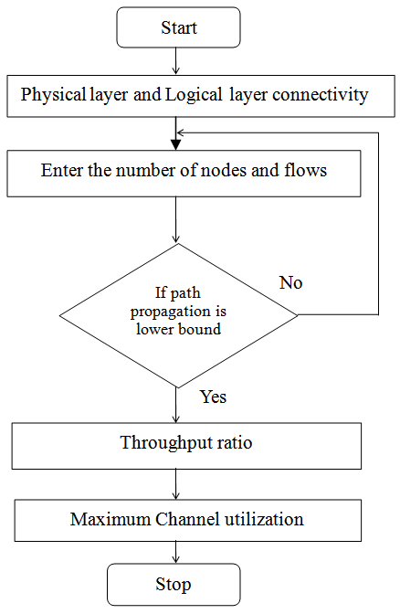 | Figure 6. Spatial Channel location method-1 |
 | Figure 7. Spatial Channel location method-2 |
 | Figure 8. Spatial Channel location method-3 |
6) Optical channel resource sharing: It ensures fairness of distribution of packets in terms of location dependent and location independent methods in order to perform propagation.7) Optical Channel Capacity: It provides the communication of a channel in order to calculate the information capacity for a given network.8) Quality of Service (QoS): It provides the basic connectivity and its performance is measured by input, output and throughput.
3. Design and Implementation
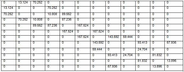
Table 3.1. Digital Cross connectivity matrix
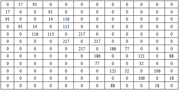 |
| |
|
Table 3.2. DS0 Digital Cross connectivity matrix in Mbps
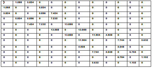 |
| |
|
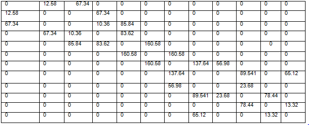
Table 3.3. DS1 Digital Cross connectivity matrix in Mbps
 |
| |
|
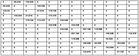
Table 3.4. DS0 Digital Cross connectivity matrix in MHz
 |
| |
|
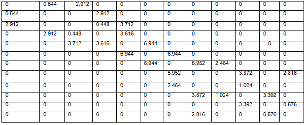
Table 3.5. DS0 Digital Cross connectivity matrix in MHz
 |
| |
|
 | Table 3.6. Bandwidth (DS1-DS0) |
4. Conclusions
Optical communication represents the physical layer by means of guided media. It establishes different node connectivity in a network and also establishes the physical path between transmitter and receiver. The logical layer enhances multilayer network topology in order to ensure the spatial locality and maximum utilization of optical channel capacity.This work can be carried out by using different algorithms in a distributed manner with statistics and as well as stochastic methodologies.
References
| [1] | Cvijetic, M., and Djordjevic, I.B., Advanced Optical Communication Systems and Networks, 2013, Arctech House, Newton, MA. |
| [2] | Winzer, 651 Networking Beyond WDM, “IEEE Photonics P.J., “Optical Journal, Vol. 4, No. 2, April 2012, pp. 647- 651. |
| [3] | Argawal, G.P., Fiber-Optic Communications Systems, Fourth Edition, 2010, Wiley, Hoboken, NJ. |
| [4] | T H WU and R H Cardwell. ‘Optimum routing for fiber network design: model and applications’ proceedings of IEEE, Information communications conference (ICC), Philadelphia, PA, June 1988, P2.5.1. |
| [5] | T H WU, DJ Kolar and R H Cardwell. ‘Survivable network architectures for broad band fiber networks: model and performance comparisons’. IEEE journal of light wave technology Vol 6, no 11, November 1988, p 1698. |
| [6] | Song-HO WU. T., David J. Kolar and Richard H. Cardwell, “Technologies for Planning a Survivable Fiber Network Architecture Using Optical Switches”, IEEE Journal of Selected Areas in Communications, Vol. 8, No. 2, 1990, pp. 152-159. |

 Abstract
 Reference
 Full-Text PDF
 Full-text HTML