Shamshad Akther Khan, M. A. Hasnayeen
Computer Science and Engineering, International Islamic University Chittagong, Chittagong, Bangladesh
Correspondence to: Shamshad Akther Khan, Computer Science and Engineering, International Islamic University Chittagong, Chittagong, Bangladesh.
| Email: |  |
Copyright © 2015 Scientific & Academic Publishing. All Rights Reserved.
Abstract
An Aluminum Indium Gallium Indium Phosphate based vertical cavity surface emitting laser structures with precisely adjusted resonated-cavity wavelengths. DBR modeling has been also implemented in this paper. The theory of optical multilayer is reviewed and the Characteristics Matrix method has been used to calculate the multilayer. All the calculation was performed using Matlab.
Keywords:
VCSEL, Quantum well, DBR, Cavity, Refractive index, Multi-Quantum well, Reflectivity, Transmisitivity, Resonator, Bragg wavelength
Cite this paper: Shamshad Akther Khan, M. A. Hasnayeen, Modeling of Low Power Multilayer Vertical Cavity Surface Emitting Laser, International Journal of Optics and Applications, Vol. 5 No. 5, 2015, pp. 155-160. doi: 10.5923/j.optics.20150505.03.
1. Introduction
The development of AlGaInP quantum well lasers has been driven by the requirement for short wavelength sources in optical disc information storage systems, the general utility of compact, battery powered visible sources and use as pump sources in solid state laser systems. Such devices are also of use in short haul optical data links using polymer fibers and waveguides and as light sources in photodynamic therapy. The applications have led to the requirement for enhanced functionality in these structures. Several material related limitations make the design of the short wavelength lasers difficult and further progress requires fabricated structures and integrated with other system components such as filters and detectors. At the present time the short wavelength of most commercial services is 635nm, and is limited to low power. However, shorter wavelength lasers are required, particularly for data storage, and in the treatment of cancer using 630nm absorption and PDT drugs.The objective is to reduce the use of number of DBR layer and increase the reflectivity. The whole task was carried out by 635nm wavelength. Since we have carried out the whole work by dividing it into three parts Appendix A, Appendix B and Appendix C. We shall mention our objectives based on the respective appendix.In appendix A, Choosing the appropriate material combination for first layer, second layer, substrate layer and to provide reflectivity not less than 89% with less number of DBR layer are the main objective. Where as in appendix B, Choosing the appropriate material combination for well and barrier and to provide reflectivity not less than 89% with appropriate number of QW are the main objective. In appendix C, finding out the exact position to place the resonator are the main objective.
2. VCSEL Fundamantals
The vertical-cavity surface emitting laser (VCSEL) is a type of semiconductor laser device emits laser perpendicular to the chip surface contrary to its counterpart edge emitting semiconductor lasers (EELs). The vertical-cavity surface emitting laser (VCSEL) is a relatively new semiconductor device among the other optoelectronics devices.
2.1. VCSEL Structure
Typical VCSEL dominant structural components can be divided into two components: the upper and bottom DBRs, and the centre active region. These DBRs will create a high-finesse Fabry-Perot cavity within, which are placed integer multiples of half wavelength-thick  quantum-well active regions [8, 4]. On the other hand DBRs consist of repeating pairs of quarter-wavelength-thick high and low-refractive index semiconductor layers. Therefore by combining the multiple quarter-wavelengths thick of high-to-low refractive index layers will result in a maximum reflectance greater than 99% [8].
2.2. VCSEL Versus EEL
Vertical Cavity Surface Emitting Laser (VCSEL) has many fascinating advantages over Edge Emitting Laser (EEL) that are: (1) The emitted beam characteristics of VCSEL can be controlled by the number of parameters like number of DBRs, thickness of DBRs, type of material used to fabricate the DBRs and other process parameters. This kind of fine tuning is difficult to find in EELs. (2) The typical size of emitting circular region of VCSEL is about 5 to 25μm in diameter that too short in contrast to emitting region of EEL. (3) A typical EELs requires 30mA threshold for telecom applications while VCSELs requires 1 to 2mA threshold current leads to low operating voltages. These all features push forward to use VCSELs for development of high speed optical buses and interconnect [7].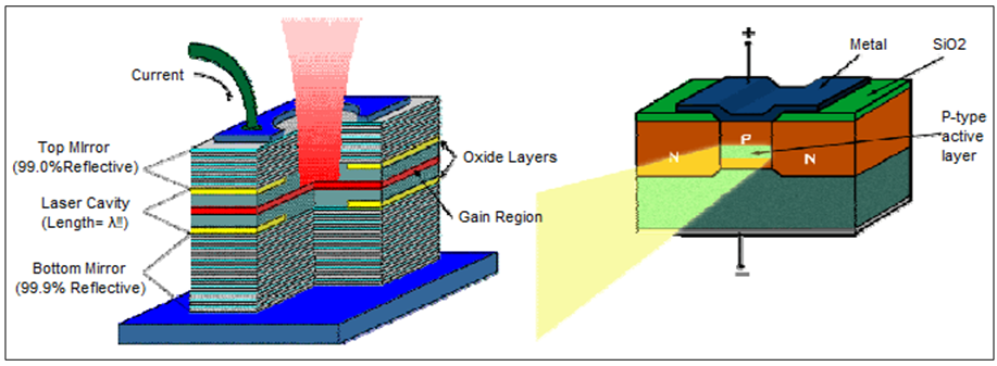 | Figure 1. Schematic diagram of VCSELs and EELs [9] |
3. DBR for VCSEL
Distributed Bragg reflectors consist of epitaxially grown, alternating periodic quarter-wavelength stacks of low and high refractive index semiconductors, which are used to provide high mirror reflectivity in numerous optoelectronic and photonic devices such as VCSEL. Finally, we need to look into the reflectance and transmittance at an interface. Next, calculate the multilayer using matrix.
3.1. Reflection and Transmission of DBR
A DBR is a structure formed from multiple layers of alternating materials with varying refractive index, or by periodic variation in the effective refractive index in the guide. The DBR’s reflectivity, R for intensity is approximately given by | (1) |
Where  and
and  are the respective refractive indices of the originating medium, the two alternating materials, and the terminating medium and N is the number of repeated pairs of low or high refractive index material [6].
3.2. Methods for Calculating the Reflection Coefficient
There are several methods to calculate the reflection coefficient of a multilayer stack, here transmission method will be used. The phase change of electromagnetic radiation passing through the mth layer. | (2) |
Where  is the wavelength of the radiation,
  is the thickness of the mth layer that is expressed by.
 | (3) |
Where  is the Bragg wavelength and
  is refractive index of mth layer [1].
3.3. Reflectance and Transmittance at the Interface
The reflectance R and transmittance T are defined as the ratio of the reflected and transmitted waves respectively to the incident wave. Because the amplitudes of the reflected and transmitted wave are complex quantities so their arguments gives us phase response of reflected and transmitted wave. The reflected or transmitted light can be determined by applying the boundary conditions to the Maxwell’s equation [7].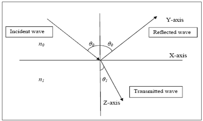 | Figure 2. Reflection Phenomena at an interface [7] |
We can obtain the ratios of the transmitted and reflected amplitudes to incident amplitudes for each component of polarization that give us the expressions for the Fresnel coefficients of reflection and transmission [7]. | (4) |
 | (5) |
Where Rs is the reflection coefficient and Ts is the transmittance coefficient. | (6) |
The above expression is valid when n0 and n1 are real.
3.4. Transmission Matrix Formulation for Multilayer
The matrix method is easiest and versatile method for calculating the spectral coefficients of the layered media. For the modeling of DBRs, if MT represents the product of characteristic matrices of the mirrors and M i=1, 2 represent the individual layers in a stack then [7]. | (7) |
Where p is the number of periods, Mi is the characteristic matrix and is given by. | (8) |
The above equation gives an expression to calculate coefficient B and C. Finally the transmittance, the reflectance, the phase changes respectively can be calculated. | (9) |
 | (10) |
 | (11) |
3.5. VCSEL Resonator Design
All Determination of the percentage of transmissivity and reflectivity, completes just one part of the work. VCSEL not only consists of DBR mirrors, they also contain centre active region. So the results must be determined based on the resonator incorporated with multilayer.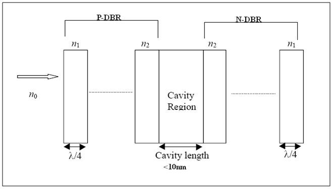 | Figure 3. A Typical Resonator Structure |
Finally, the modified Characteristic Matrix involves calculation for upper layers, cavity region and bottom layers. | (12) |
Where Mu is the characteristic matrix of upper layers, Mc is the characteristic matrix of cavity region and Mb is the characteristic matrix of bottom layers.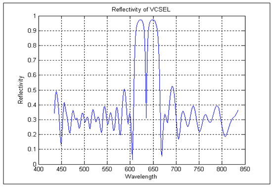 | Figure 4. Reflectivity versus Wavelength |
The centre dip represents the Bragg wavelength, 635nm. We can achive the reflectivity of 30% at 635nm. In Transimitivity versus Wavelength graph we obtain approximately 70% value at 635nm. The results satisfies the requirement as exhibited in equation (9) and (10).
3.6. Electric Field Intensity
Various studies regarding high power laser mirrors have demonstrated that damage of multilayer is caused by high intensity due to current density absorption. So it is important to find this region and overcome such kind of damage by the reducing the absorption in the multilayer. To do so we need to find the intensity inside the multilayer [3]. Figure 5 illustrates the concept of calculating the intensity inside the multilayer.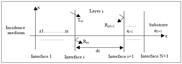 | Figure 5. Field Intensity Calculation [3] |
The positive and negative going EM wave at some point z, where z is greater than zi but less that zi+1 in the ith layer are related to amplitude reflection and transmission coefficient at the interface of that layer. Using this positive and negative EM the intensity can be calculated [3]. | (13) |
Where the intensity is found high, the damage occurs in that interface, this region is where the most of the current density is absorbed. In order to control the peak of the electric field intensity, a resonator is included in the multilayer. This resonator helps to equalize the peak electric field of the interface and increase the reflectance.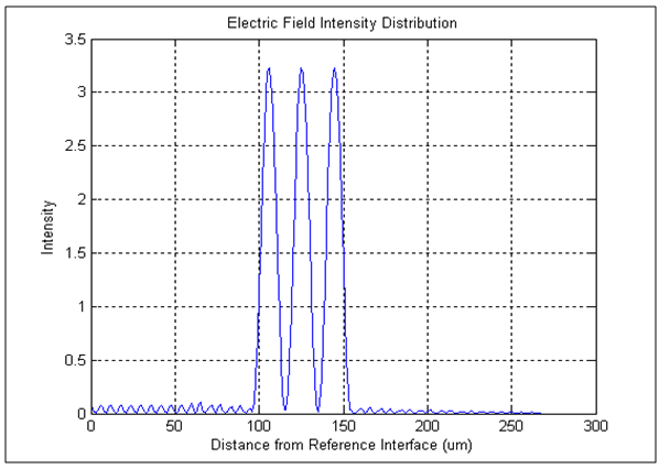 | Figure 6. Electric Field Intensity Distribution with Resonator |
Figure 6 shows the electric field intensity inside a AlGaInP VCSELs. It can be observed that strong electric field intensity occurred in the resonator and the electric field intensity starts to diminish after it has passed the resonator region. From this information, we can correctly determine where to place our active region in the AlGaInP VCSELs.
4. Conclusions
This paper has shown that by using Matlab, optimal results can be obtained. It has been shown that by simply adjusting the number of mirrors, it will significantly affect the overall reflectivity as well as transmissivity. Moreover, it can be noted that by changing the substrate medium, different reflectivity and transmissivity results can be obtained. Lastly, the electric field inside the multilayer will be reduced and finally disappear at layer 29-30.One might look forward for following future work. Determining the electric field intensity at non-normal incidence, Determining the electric field intensity for different wavelength, Methods of reducing the peak electric field intensity, Determining an optimum resonator for VCSEL, Develop the rate equation, Determine the output of the LASER via Rate Equation.
ACKNOWLEDGEMENTS
Introducing the topic of my report and what I have learned, I’d like to Acknowledge Thanks to all of those who have been involved in creating the present status of the report, besides those who have helped me with physically and verbally.Firstly, much thanks to teachers, and all those who have run a routine check on the progress of my report. It’s partly them, who granted me the idea for building, experience enhancement, deeper thinking, widening my horizons and building me as a ‘Women of Tomorrow.’Secondly, a good amount of thanks, I give to my supervisor, for co-operation and assessment in the thesis process. It’s more to him, for thesis ideas was proceeding to right direction. Thanks to you for holding my high esteems towards the end of the thesis. A woman can never go by doing everything herself, so would I without your help. Thanks, and thanks a lot.Thirdly, bunch of thanks to my parents for helping me financially and spiritually. Without your encouragements, I would have accomplished nothing. Thanks to you for being my always-helping hand.Lastly, I am here with a mission from God, and it is to be on His path and to acquire His Glory. Knowledge is His path, so is the path I have selected. If not, by thy Glory I would but be helpless creature. Glories to thee and thanks to thee for helping me, and by thy mercy accept my humble work.
References
| [1] | Babar BASHIR., “Designing of high reflectance distributed bragg reflectors (DBRs), mirrors using AlGaInN material system in the UV wavelength range”, June 2009. |
| [2] | B.E. Newnam, “Damage resistance of dielectric reflectors for picosecond pulses,” Laser Induced Damage in Optical Materials, Nat. Bur. Standards, Washington, DC, USA, xx+235, pp. 39-47, 1974. |
| [3] | H.M. Liddell, Computer-aided techniques for the design of multilayer filter, Adam Hilger Ltd, Bristol, 1980. |
| [4] | J.L. Jewell, “Vertical-cavity surface-emitting lasers: design, growth, fabrication, characterization,” IEEE Journal of Quantum Electronics, Vol.27, pp. 1332-1346, June 1991. |
| [5] | O.S. Heavens, Optical Properties of Thin Solid Films, Butterworths Scientific Publications, London, 1955. |
| [6] | Sheppard, C.J.R., "Approximate calculation of the reflection coefficient from a stratified medium". Pure and Applied Optics: Journal of the European Optical Society Part A 4 (5): 665. Bibcode 1995PApOp4. .665S. doi: 10.1088/ 0963-9659/ 4/ 5/ 018, 1955. |
| [7] | Wee Khiang Ace Tey., “Design of low threshold vertical-cavity surface-emitting lasers”, Master thesis, University of Queensland, October 2000. |
| [8] | W.W. Chow, “Design, fabrication and performance of infrared and visible vertical-cavity surface-emitting Lasers,” IEEE Journal of Quantum Electronics, Vol. 33, No. 10,, pp. 1810-1824, October 1997. |
| [9] | http://www.fi.isc.cnr.it/users/giovanni.giacomelli/Semic/Samples/samples.html. |
 Abstract
 Reference
 Full-Text PDF
 Full-text HTML