Purnomo Sidi Priambodo 1, Ucuk Darusalam 1, 2, Eko Tjipto Rahardjo 1
1Department of Electrical Engineering, Universitas Indonesia, Depok, Indonesia
2Department of Informatics Engineering, Faculty of ICT, Universitas Nasional, Jakarta, Indonesia
Correspondence to: Purnomo Sidi Priambodo , Department of Electrical Engineering, Universitas Indonesia, Depok, Indonesia.
| Email: |  |
Copyright © 2015 Scientific & Academic Publishing. All Rights Reserved.
Abstract
Terrestrial free-space optical communications (FSOC) is potential to be applied in microcellular networks to provide larger bandwidth and higher cellular access. However, the terrestrial propagation quality degrades due to atmospheric absorption and turbulence. Turbulence-induced noise degrades signal to noise ratio (SNR) and increases bit error rate (BER), which finally degrades the overall signal quality at the receiver. In this paper, we propose to develop a method and conduct a laboratory experiment to suppress turbulence noise by using a pinhole as Fourier optics low-pass filter. It is shown that pinhole can improve BER very significantly from 10-7 down to 10-11, even in strong noisy medium propagation.
Keywords:
Free-space optical communications, Optical turbulence, Noise propagation, Noise fading, Optical filters, Spatial Fourier transforms, Pinhole, Signal-to-noise ratio, Bit-error-rate, Noise suppression
Cite this paper: Purnomo Sidi Priambodo , Ucuk Darusalam , Eko Tjipto Rahardjo , Free-Space Optical Propagation Noise Suppression by Fourier Optics Filter Pinhole, International Journal of Optics and Applications, Vol. 5 No. 2, 2015, pp. 27-32. doi: 10.5923/j.optics.20150502.01.
1. Introduction
FSOC is very promising to be applied in the future for deep-space and terrestrial communications [1-2]. It is very attractive due to its large bandwidth, close to fiber optics and flexibility of point to point communication such as microwave systems. Moreover, the most interest is due to its low cost investment.Beside of thus promising points, however, FSOC technology has major weaknesses that have to be overcome, which are the existence of static attenuation and temporal or dynamic intensity fluctuation. Static attenuation is caused by absorption and light scattering due to various atmospheric gases and particles in atmospheric propagation medium, while, the dynamic intensity fluctuation is caused by atmospheric turbulence, which is due to temporal and spatial temperature gradient in atmosphere. The atmospheric turbulence produces various distributions of pockets of non-homogeneity optical medium as refraction zones. These refraction zones act as multiple lens effects. If the size of turbulences is only about a several wavelengths of the light, then it is called as micro turbulences that cause optical scattering and attenuation, where the optical axis path is considered remains the same. The temporal micro turbulences produce high frequency intensity fluctuation noise at the receiver. If the size of turbulences are sufficiently large or called as macro turbulence, these cause beam wandering effect, which lead to shift optical axis from transmitter (TX) to receiver (RX). The beam wandering causes slow intensity fluctuation at RX, it is called as turbulence-induced fading. The overall effects, high frequency fluctuation noise and fading limit propagation distance and bandwidth of FSOC [3-6]. Turbulence-induced noise and fading at RX has been studied and investigated extensively. Several techniques have been developed to model Turbulence-induced noise and fading [7-9]. There are at least 2 (two) important statistical parameters related to turbulence-induced noise and fading, i.e. (1) d0, the correlation length of random intensity fluctuation and (2) τ0, the correlation time of random intensity fluctuation [10]. Several improvements on detection techniques have been developed based on statistical properties of turbulence-induced noise and fading by temporal or spatial-domain technique approaches. In temporal domain technique approach, RX should be designed such that RX observation interval T0 > τ0, where turbulence-induced noise can be much reduced by temporal-averaging method at the RX. In the same way, for spatial domain technique approach, RX aperture diameter D0 > d0, such that turbulence-induced fading can be much reduced by spatial-aperture averaging method at RX. Another improvement on spatial-aperture averaging method is in the form of spatial diversity method that is applying multi TXs and multi RXs, which is called multi-input multi-output (MIMO) and combined with Q-ary pulse-position modulation (QPPM) [11]. Several research groups have achieved developing FSOC for middle distance up to 1-km with 10-Gbps bit rate [12].In this paper, we propose to overcome the turbulence-induced noise on FSOC by using a different way. Instead of suppressing the turbulence-induced noise by using temporal and spatial-domain statistical technique approaches as explained above, we propose to use Fourier optics filter concept. Atmospheric turbulence along the propagation medium produces a high frequency temporal and spatial fluctuated wavefront right in front of the RX lens. The fluctuated wavefront based on Fourier optics analysis concept, consists of fundamental and higher-order spatial harmonic planar wavefronts. The temporal noise mostly rides on the higher-order ones. Pinhole as a low pass Fourier optics filter and common to be used in interferometric process [13], is used to suppress the higher-order spatial harmonics (consisting noisy signal parts) of the receiving turbulence-induced noise. After pinhole filter, the detector receives clean signal, which is the fundamental order of optical carrier modulated by the information signal. In this paper, suppression is limited on high frequency fluctuation noise and not the fading, due to the limitation of our laboratory experiment.
2. Noise Suppression Mechanism
The received wavefront as noisy information carrier is received by the receiving lens aperture, and focused onto the detector. The light focusing process is an equal gain combining detection process. Ideal condition is the receiver diameter D0 >> d0, the equal gain combining detection averages the received noisy signal and can vanish the addition noise on the signal. However, mostly the condition is D0< d0. The limitation of receiving aperture diameter causes RX lens focusing system cannot perfectly average the received noisy wavefront in order to clean the noise. At the focal point, the light beam looks like a waist. For a detector that has an area larger than the beam waist area and located right behind the focal point, then the overall received signal that consists of temporal noises and the original signal will be detected by detector. This decreases SNR and increases BER.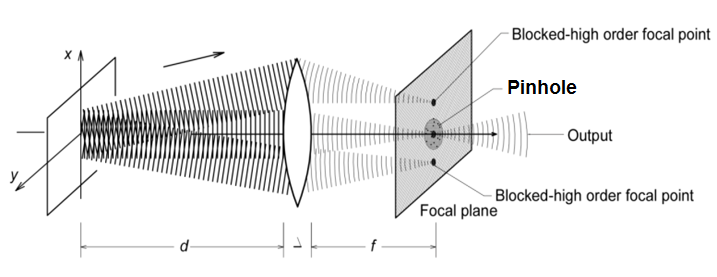 | Figure 1. Pinhole blocks higher-order spatial harmonic focal-points [13] |
In this paper, we propose that the received noisy wavefront is constructed by superposition of fundamental clean signal and noisy harmonic planar wavefronts, which propagate off the optical axis, as shown on Fig.1 [13]: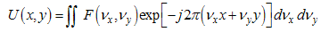 | (1) |
 | (2) |
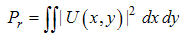
where νx and νy are the spatial frequencies in x and y directions in x-y plane, respectively and F(νx ,νy) is the amplitude of the mixing spatial frequencies and U(x,y) is the total electromagnetic field at point (x,y). The total received power at receiving lens is Pr and the fundamental or clean signal power is P0. The SNR without filtering can be expressed as,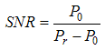 | (3) |
The receiving lens works as a spatial Fourier transformer. It transforms the temporal-spatial noisy input wavefront to be spatially harmonic focal points on the focal-point plane. On the focal point plane of the receiving lens exists various focal points of each harmonic planar wavefronts surrounding the center of the fundamental focal point.In this filtering process, pinhole works to block the higher-order spatial harmonic focal points. Only fundamental order wavefront can pass the pinhole to reach the receiving detector. In this case, pinhole acts as a Fourier optics low-pass spatial filter. It blocks higher-order spatial harmonics, which are overridden by temporal noise at focal points.Pinhole suppresses the noise and improves the receiving SNR. Only fundamental spatial order that brings clean information signal is expected to be detected by the receiving detector. The SNR by using pinhole will be drastically increased, even though the total receiving power decreases. Fig. 2 may help to briefly elaborate how pinhole can suppress turbulence-induced noise, such as illustrated by scheme on Fig.1. Fig.2 (a) shows the mixing clean signal and propagation noise at the detector, a distance from the focal point. Fig.2 (b) shows that the pin-hole can suppress higher order spatial harmonics overridden by temporal turbulence noise. The detector should be located about the center, which is clean modulated signal. Fig. 2(a-b) were taken for ilustration based on a simple Fourier optic filtering by pinhole configuration in the laboratory.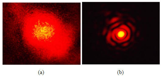 | Figure 2. Observation images on observation screen, (a) without pinhole and (b) with pinhole |
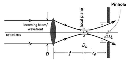 | Figure 3. Receiving lens and pinhole alignment |
Pinhole is located behind the focal point, as shown on Fig.3. The pinhole diameter has to be equal or slightly larger than the beam waist, in order that the whole clean signal can be detected, while the higher-order spatial harmonics are blocked. The relationship between receiving lens and beam waist radius at focal-point is formulated in the following Eq.(4) based on Ref. [13]. | (4) |
where D is the receiving wavefront diameter right in front of the receiving lens. D0 is the beam waist diameter at focal point, f is the focal length and λ is the wavelength. In this experiment, the receiving beam diameter is 5-cm and focal distance is 15-cm, then the beam waist diameter at focal point is 3.82λ. Based on experience, the pinhole diameter size of 3.82λ, where λ=1550-nm, is very difficult for optical alignment, and facing problem when beam wander exist. To anticipate the difficulty in optical alignment due to beam wandering effect that sometimes occurs in FSOC, it is recommended to locate pinhole not exactly right on focal-point. Pinhole should be shifted from focal point at least about Rayleigh range or a half of depth of focus [13] and pinhole diameter enlarged at minimum of √2 times as shown on Fig.3. The Rayleigh range (z0) is expressed as, | (5) |
For the above typical example, the pinhole is suggested to be located at distance about 4πλ from focal point with pinhole diameter at least 5.4λ. Based on our experience, pinhole diameter range from 6 – 30 λ is good to be exercised.To estimate the SNR gain due to pinhole effect and to simplify derivation, it needs to assume that the noise power is distributed equally from low to high spatial frequency noise. SNR gain is defined as an SNR comparison between different pinhole diameters. Assuming that the fundamental clean signal waist radius is R0 = 0.5 D0 at focal plane of receiving lens and R1 is small and R2 is large pinhole radii, by recalling Eq.(3), then the SNR gain can be formulated as: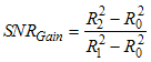 | (6) |
To estimate BEP, it needs to assume that the turbulence channelis a log-normal distribution model [14, 15] as a representation of weak-turbulence inside the propagation simulator box. The spatial spectral distribution as a result of Fourier optical transformation by the receiving lens should represent the probability density distribution of the receiving signal. The modulation is on-off keying (OOK). By assuming that the noise due to turbulence is a Gaussian distribution and larger than the receiver noise figure, then the BER improvement or gain formula can be derived from Ref [16]. The probability of error when receiving a transmitted ‘1’ is: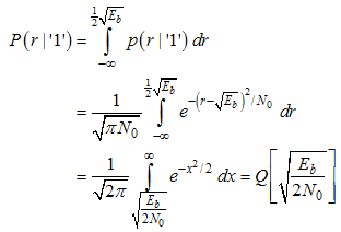 | (7) |
The probability of error when receiving a transmitted ‘0’ is: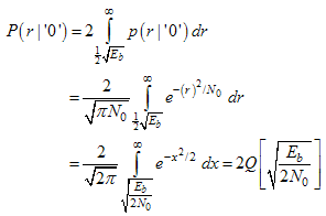 | (8) |
where p(r|'1') and p(r|'0') probability amplitude error distribution functions for transmission '1' and '0' respectively. Q or complementary error function is the tail probability in a Gaussian random variable, r is random amplitude error. Eb is the received bit energy and No is noise intensity due to turbulence or signal covariance at the focal plane of the receiving lens: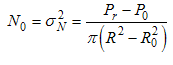 | (9) |
where Pr is total received power and P0 is the fundamental clean signal and R and R0 are radii of beam waist of total signal and fundamental signal, respectively at the focal plane of the receiving lens.Since the signal ‘1’ and ‘0’ are equaly likely to be transmitted, then the overall average probability of error is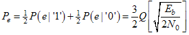 | (10) |
The probability of error Pe or sometimes is called as bit error probability (BEP) is the expectation value of bit error rate (BER). The value of Eb/No is simply corresponded with SNR. Then Eq.(10) can be written as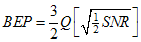 | (11) |
The BEP improvement (BEPGain) of the small radius pinhole R1 in comparison to the large radius pinhole R2 is written as: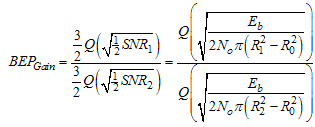 | (12) |
3. Experiment
The experiment set-up shown on Fig.4 is to prove noise suppression by pinhole. This set-up is designed for wavelength of 1550-nm, which is the favorite wavelength for terrestrial FSOC propagation. It is intended to prove the improvement of BER performance for FSOC using pinhole filter. The propagation simulator box as shown, consists of 2 types of propagation channels, one is affected by air turbulence due to air flow through obstacles and water vapor (as shown as upper part). The second one is not affected by turbulence unless beam divergence less than 50 (the lower part). The overall dimension of the box is 4m x 1m x 0.5m. The in-flow air has temperature of 140C, while the hot water vapor has temperature of nearly 1000C, sufficient to create multiple lens scattering and absorption effects. For this experiment, we assume it is sufficiently to model a weak- turbulence condition that fit to a log-normal distribution. 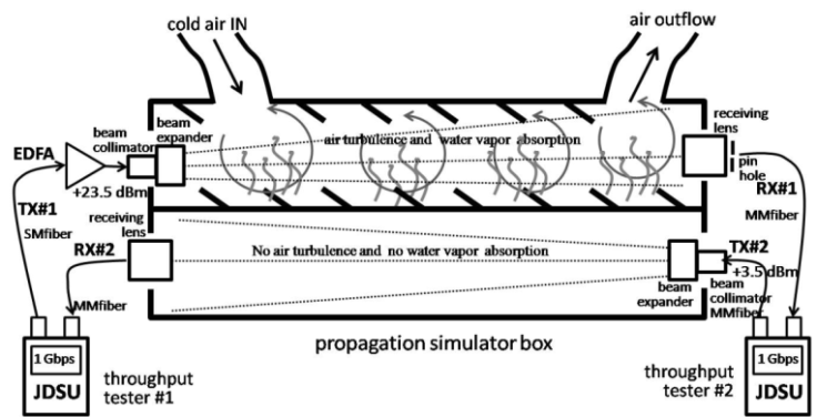 | Figure 4. Experiment set-up for filtering turbulence-induced noise by pinhole. The set-up uses Erbium-doped fiber amplifier (EDFA) 26.0 dB gain with maximum output 23.5 dBm and JDSU is a brand of 1 Gbps full-duplex TX-RX and BER-meter |
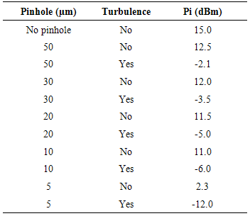
In order to prove the enhancement on detection quality by using pinhole, the comparison between non-pinhole and various diameters of pinhole detections are investigated. Various diameters of pinhole are used, i.e. 50-μm, 40-μm, 30-μm, 25-μm and 20-μm, which is located about 20 – 25 μm behind the focal point. To give insight of the measurement values, the following Table 1 shows the measurement levels for various pinhole diameters.Table 1. Average Power Measurement in Reference and Turbulence chambers, where TX power (after EDFA) is 23.5 dBm and Pi is the received signal power
 |
| |
|
4. Discussion and Analysis
Fig.5 shows the experiment measurement and theoretical results, when various sizes of pinhole are applied. Fig.5 shows both measurement results and theoretical calculations based on Eq. (11). It shows that when pinhole diameter getting smaller, then the performances of BER is improved (to lower value). It proves our proposed hypothesis that smaller pinhole diameter will block more higher-order spatial harmonics, which are overridden by temporal noise, in comparison to the larger diameters. It agrees with the theoretical derivation as well. 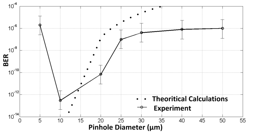 | Figure 5. Bit-error-rate (BER) measurement and theoretical calculations Vs. various pinhole diameters. The theoretical calculations use the following assumptions: Eb= 8.110-12 Watt-sec; No = 7.010-9 Watt/mm2 and 1-Gbps bit rate |
However, there is a situation that contradictive with our hypothesis. When pinhole diameter is less than the optimal diameter (in this case the optimal diameter is 6-μm), then the BER degrades to the higher value. The reason of this condition is because that the receiving power signal is getting smaller and will compete with the detector noise figure.The weakness of pinhole implementation for optical noise filtering is in the condition when beam wander occurs as the result of atmospheric turbulence. Pinhole filtering system is not immune from beam-wander effect, the system will temporally be misalligned and produce fading effect. In order to take the benefits of pinhole advantages in suppressing high-order spatial noises and to avoid the weakness of pinhole from beam-wander effect, our research group, since a year ago has developed detection system by replacing pinhole with charge-coupled device (CCD) array detector and controlled by pinhole signal processing algorithm. The pinhole will be removed in the future, however the function of pinhole in suppressing the noise still exist represented by the pinhole algorithm controlling the receiving CCD array detector. The fading due to beam wander effect is able to be reduced, since the CCD detector can always detect the receiving moving beam.
5. Conclusions
A new idea of propagation noise suppression in FSOC, by using a pinhole as a Fourier optics low-pass filter has been presented. By experiment, it has been proven to improve BER performance in medium turbulence-induced fading propagation from 10-7 down to 10-11 (up to 10+4 BER improvement), even more. Furthermore, this proposed filtering method can also be implemented for applications with longer wavelength such as in RF technologies to suppress the propagation noise due to turbulence atmosphere.
ACKNOWLEDGEMENTS
This work is funded by research grant BOPTN Universitas Indonesia 2014. The authors declare that there is no conflict of interests regarding to the publication of this manuscript and this manuscript is original work and never been published elsewhere.
References
| [1] | H. Hemmati, A. Biswas, I.B. Djordjevic, "Deep-Space Optical Communications: Future Perspectives and Applications," Proceedings of the IEEE, 99 (2011) 2020–2039. |
| [2] | C.C. Davis, I.I. Smolyaninov and S.D. Milner, "Flexible optical wireless links and networks," IEEE Communications Magazine, 41 (2003) 51-57. |
| [3] | S. M. Navidpour, M. Uysal and M. Kavehrad, “BER Performance of Free-Space Optical Transmission with Spatial Diversity,” IEEE Transactions on Wireless Communications, 6 (8), pp. 2813–2819, August 2007. |
| [4] | M. Ijaz, Z. Ghassemlooy, J. Perez, V. Brazda, and O. Fiser, "Enhancing the Atmospheric Visibility and Fog Attenuation Using a Controlled FSO Channel," IEEE Photonics Technology Letters, 25(13), pp.1262–1265, July 2013. |
| [5] | H. Kaushal, V. Kumar, A. Dutta, H. Aennam, V. K. Jain, S. Kar, and J. Joseph, "Experimental Study on Beam Wander Under Varying Atmospheric Turbulence Conditions," IEEE Photonics Technology Letters, 23(22), pp. 1691–1693, November 2011. |
| [6] | Hennes Henniger, "Transmission Performance Analysis of Free-Space Optical Communications using Gilbert-Erasure Channel," IEEE Transactions on Wireless Communications, 60 (1), pp. 55–61, January 2012. |
| [7] | M. A. Khalighi, N. Schwartz, N. Aitamer, and S. Bourennane, “Fading reduction by aperture averaging and spatial diversity in optical wireless systems,” J. Opt. Commun. Netw., 1 (6), pp. 580–593, Nov 2009. |
| [8] | Jin Cheng, Yong Ai, and Ying Tan, "Improved free space optical communications performance by using time diversity," Chin. Opt. Lett. 6, pp. 797–799, 2008. |
| [9] | C. A. Rjeily and A. Slim, “Cooperative diversity for free-space optical communications: transceiver design and performance analysis,” IEEE Trans. Commun.59 (2011) 658–663. |
| [10] | Xiaoming Zhu and Joseph M. Kahn, "Free-Space Optical Communication Through Atmospheric Turbulence Channels," IEEE Trans.on Commun., 50(2002)1293–1300. |
| [11] | Stephen G. Wilson, Maite Brandt-Pearce, Qianling Cao and James H. Leveque, "Free-Space Optical MIMO Transmission With Q-ary PPM," IEEE Trans. on Commun., 53(2005)1402–1412. |
| [12] | K. Wakamori, K. Kazaura, and Ikuo Oka, “Experiment on regional broadband network using free-space-optical communication systems,” J. Lightw. Technol. 25(2007) 3265–3273. |
| [13] | B.E.A. Saleh and M.C. Teich, "Fundamentals of Photonics, "A Wiley-Interscience Publication, John Wiley and Sons, Inc. Ch. 4 “Fourier Optics”, (1991) pp. 108–156. |
| [14] | L.C. Andrews and R.L. Phillips, “Laser Beam Propagation Through Random Media”, SPIE Press, 2nd Ed, Bellingham, Washington, USA,(2005). |
| [15] | Shlomi Arnon, “Effects of atmospheric turbulence and building sway on optical wireless-communication systems”, Optics Lett., 28(2003)129–131. |
| [16] | J.G. Proakis and M. Salehi, "Communication Systems Engineering," Prentice Hall, Englewood Cliffs, New Jersey 07632, (1994). |
 Abstract
 Reference
 Full-Text PDF
 Full-text HTML