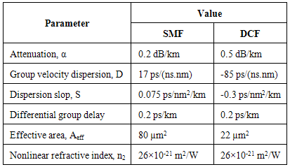
| [1] | J. Wang, and J. Sun, “All-optical ultrawideband monocycle generation using quadratic nonlinear interaction seeded by dark pulses,” IEEE Photonics Technology Letters, Vol. 22, No. 3, PP. 140-142, FEBRUARY, 2010. |
| [2] | V. Moreno, M. Rius, J. Mora, M. A. Muriel, and J. Capmany, “UWB monocycle generator based on the non-linear effects of an SOA-integrated structure,” IEEE Photonics Technology Letters, Vol. 26, No. 7, PP. 690-693, April, 2014. |
| [3] | H. Feng, M. P. Fok, S. Xiao, J. Ge, Q. Zhou, M. Locke, R. Toole, and W. Hu, “A Reconfigurable high-order UWB signal generation scheme using RSOA-MZI structure,” IEEE Photonics Journal, Vol. 6, No. 2, PP. 7900307-7900307, April, 2014. |
| [4] | S. Pan, and J. Yao, “IR-UWB-over-fiber systems compatible with WDM-PON networks,” Journal of Lightwave Technology, Vol. 29, No. 20, PP. 3025-3034, October, 2011. |
| [5] | Y. Yu, J. Dong, X. Li, and X. Zhang,” UWB monocycle generation and bi-phase modulation based on Mach–Zehnder modulator and semiconductor optical amplifier,” IEEE Photonics Journal, Vol. 4, No. 2, PP. 327-338, April, 2012. |
| [6] | P. Li, H. Chen, X. Wang, H. Yu, M. Chen, and S. Xie, “Photonic generation and transmission of 2-Gbit/s power-efficient IR-UWB signals employing an electro-optic phase modulator,” IEEE Photonics Technology Letters, Vol. 25, No. 2, PP. 144-146, January, 2013. |
| [7] | F. Zhang, S. Fu, J. Wu, N. Q. Ngo, K. Xu, Y. Li, X. Hong, P. Shum, and J. Lin, “UWB impulse radio transmitter using an electrooptic phase modulator together with a delay interferometer,” IEEE Photonics Technology Letters, Vol. 22, No. 20, PP. 1479-1481, October,2010. |
| [8] | X. Yu, T. B. Gibbon, R. Rodes, T. T. Pham, and I. T. Monroy, “System wide implementation of photonically generated impulse radio ultra-wideband for gigabit fiber-wireless access,” Journal of Lightwave Technology, Vol. 31, No. 2, PP. 264-275, January, 2013. |
| [9] | M. Beltrán, and R. Llorente, “Dual photonic generation ultrawideband impulse radio by frequency shifting in remote-connectivity fiber,” Journal of Lightwave Technology, Vol. 29, No. 24, PP. 3645-3653, December,2011. |
| [10] | P. Li, H. Chen, M. Chen, and S. Xie, “Gigabit/s photonic generation, modulation, and transmission for a reconfigurable impulse radio UWB over fiber system,” IEEE Photonics Journal, Vol. 4, No. 3, PP. 805-816, June, 2012. |
| [11] | M. Mirshafiei, A. Ghazisaeidi, D. Lemus, S. LaRochelle, and L. A. Rusch, “Upconversion of gain-switched laser pulses for optical generation of UWB signals,” Journal of Lightwave Technology, Vol. 30, No. 2, PP. 207-214, January, 2012. |
| [12] | Z. Hu, J. Sun, J. Shao, and X. Zhang, “Filter-free optically switchable and tunable ultrawideband monocycle generation based on wavelength conversion and fiber dispersion,” IEEE Photonics Technology Letters, Vol. 22, No. 1, PP. 42-44, January, 2010. |
| [13] | V. Moreno, M. Rius, J. Mora, M. A. Muriel, and J. Capmany, “UWB doublet generation employing cross-phase modulation in a semiconductor optical amplifier mach–zehnder interferometer,” IEEE Photonics Journal, Vol. 5, No. 6, PP. 7101106- 7101106, December, 2013. |
| [14] | W. Li, L. X. Wang, J. Y. Zheng, M. Li, and N. H. Zhu, “Photonic generation of ultrawideband signals with large carrier frequency tunability based on an optical carrier phase-shifting method,“ IEEE Photonics Journal, Vol. 5, No. 6, PP. 5502007-5502007, October, 2013. |
| [15] | M. Abtahi, and L. A. Rusch, “RoF delivery over PONs of optically shaped UWB signals for Gigabit/s wireless distribution in the home,“ IEEE Journal On Selected Areas In Communications, Vol. 29, No. 6, PP. 1304-1310, June, 2011. |
| [16] | Y. M. Chang, J. Lee, D. Koh, H. Chung, and J. H. Lee, “Ultrawideband doublet pulse generation based on a semiconductor electroabsorption modulator and Its distribution over a fiber/wireless link,” Journal Of Optical Communications Networks, Vol. 2, No. 8, PP. 600-608, August, 2010. |
| [17] | T. Huang, J. Li, J. Sun, and L. R. Chen, “Photonic generation of UWB pulses using a nonlinear optical loop mirror and Its distribution over a fiber link,” IEEE Photonics Technology Letters, Vol. 23, No. 17, PP. 1255-1257, September, 2011. |
| [18] | B. Luo, J. Dong, Y. Yu, and X. Zhang, “Bandwidth-tunable single-carrier UWB monocycle generation using a nonlinear optical loop mirror,” IEEE Photonics Technology Letters, Vol. 24, No. 18, PP. 1646-1649, September, 2012. |
| [19] | Y. Yu, J. Dong, X. Li, and X. Zhang, “Ultra-wideband generation based on cascaded Mach–Zehnder modulators,” IEEE Photonics Technology Letters, Vol. 23, No. 23, PP. 1754-1756, December, 2012. |
| [20] | P. Cao, X. Hu, J. Wu, L. Zhang, X. Jiang, and Y. Su, “Reconfigurable UWB pulse generation based on a dual-drive Mach–Zehnder modulator,” IEEE Photonics Journal, Vol. 6, No. 5, PP. 7903206- 7903206, October,2014. |
| [21] | W. Zhihu, W. Rong, P. Tao, S. Guodan, F. Tao, “Switchable optical ultra-wideband pulse generator based on polarization modulator,” China Communications, PP. 113-117, July, 2013. |
| [22] | Y. M. Chang, J. Lee, H. S Lee, L. Yan, and J. H. Lee, “Generation and distribution of 1.25 Gb/s Ultrawideband doublet pulses based on the combination of nonlinear polarization rotation and parametric amplification,” Journal Of Lightwave Technology, Vol. 29, No. 6, PP. 931-938, March, 2011. |
| [23] | Y. Min Chang, J. Lee, and J. H. Lee, “Bismuth nonlinear optical fiber for photonic ultrawideband radio-signal processing,” IEEE Journal Of Selected Topics In Quantum Electronics, Vol. 18, No. 2, PP. 891-898, April, 2012. |
| [24] | Y. Peled, M. Tur, and A. Zadok, “Generation and detection of ultra-wideband waveforms using stimulated brillouin scattering amplified spontaneous emission,” IEEE Photonics Technology Letters, Vol. 22, No. 22, PP. 1692-1694, November, 2010. |
| [25] | E. Zhou, X. Xu, K. S. Lui, and K. K. Y. Wong, “Photonic ultrawideband pulse generation with HNL-DSF-based phase and intensity modulator, “ IEEE Photonics Technology Letters, Vol. 23, No. 7, PP. 396-398, April, 2011. |
| [26] | A. Zadok, Xi. Wu, J. Sendowski, A. Yariv, and A. E. Willner, “Photonic generation of ultra-wideband signals via pulse compression in a highly nonlinear fiber,” IEEE Photonics Technology Letters, Vol. 22, No. 4, PP. 239-241, February, 2010. |
| [27] | J. Zheng, N. Zhu, L. Wang, J. Liu, and H. Liang, “Photonic generation of ultrawideband (UWB) pulse with tunable notch-band behavior,” Vol. 4, No. 3, PP. 657-662, June, 2012. |
| [28] | C. Yang, L. Xia, S. Fu, and D. Liu, “Reconfigurable UWB pulse generation based on multi-taps and a programmable filter,” IEEE Photonics Technology Letters, Vol. 26, No. 14, PP. 1395-1398, July, 2014. |
| [29] | E. Zhou, X. Xu, K. S. Lui, and K. K. Y. Wong, “A power-efficient ultra-wideband pulse generator based on multiple PM-IM conversions,” IEEE Photonics Technology Letters, Vol. 22, No. 14, PP. 1063-1065, July, 2010. |
| [30] | H. Feng, S. Xiao, L. Yi, and W. Hu, “Photonic generation of reconfigurable orders ultrawideband signals by using cascaded RSOAs,” IEEE Photonics Technology Letters, Vol. 26, No. 9, PP. 908-910, May, 2014. |
| [31] | S. Pan, and J. Yao, ”UWB-over-fiber communications: modulation and transmission,” Journal of Lightwave Technology, Vol. 28, No. 16, PP. 2445-2455, August, 2010. |
 Abstract
 Reference
 Full-Text PDF
 Full-text HTML
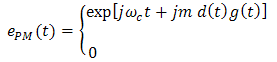
 is the angular frequency of the optical carrier, m is the phase modulation index,
  is a normalized Gaussian pulse, and d(t) is the input binary data. The binary data d(t) is given by
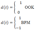
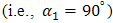
 and
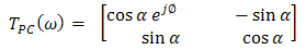
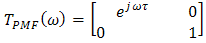
and  are, respectively, the rotation angle and phase shift introduced by the PC while
  represents the time delay between the two polarization components introduced by the PMF. The complex transfer function of the cascaded optical components (three PCs and two PMFs) can be computed using the following relation
 is the Fourier transform of the phase modulated signal and given by
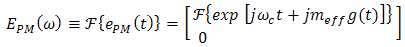
 denotes the Fourier transform of the argument and
  represents the effective phase modulation index;
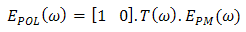
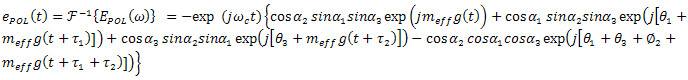
  with d(t) takes the values 0, 1, or -1 according to the logic states and signaling format. Following the analysis reported in [31], the optical field at the polarizer output can be expressed in frequency and time domains as follows
 stands for the inverse Fourier transform,
  and
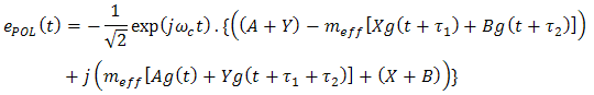
and  .
.  and let
  ,
,  [31]. Equation 8 is simplified to
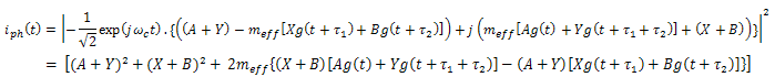
 ,
,  and using the identities
  and
and 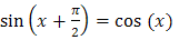 yields
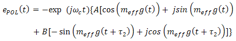
 is very small,
 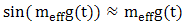 and
and 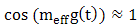 , then
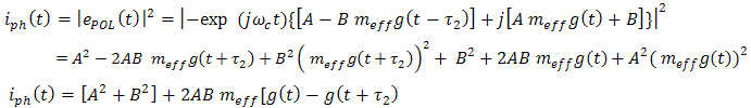
 in addition to a DC term
 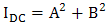 . Note that both
  and
and  depend on the PCs rotation angles
  and
and 

 which is adopted in [31], eqn. 12 reduces to that reported in [31].
 with principal axis of PMF1
  and let
  ,
,  [31]. Equation 8 is simplified to
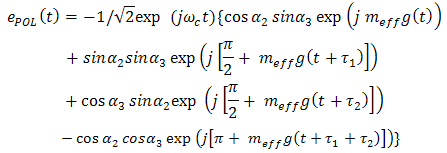
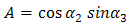
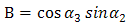
 and
and 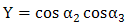 , then using the two trigonometric identities adopted in section 3.1 yields
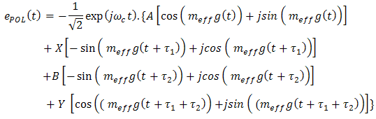
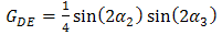
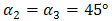
 in addition to an ac term that reflects the second-order difference components. For special case of
  which is adopted in [31],
  . This yields an ac term that is proportional to
 . This result is in accord with that in [31].
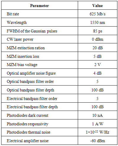
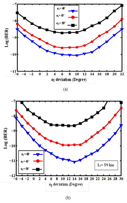
 deviation for different values of
  after transmission over SMF for (a) Gaussian monocycle OOK (b) Gaussian monocycle BPM (c) doublet OOK (d) doublet BPM
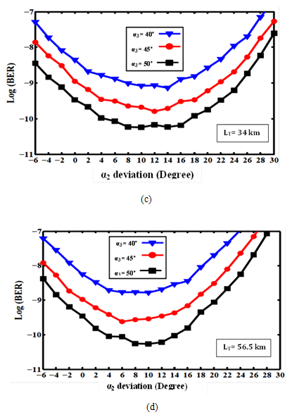
 deviation for different values of
  after transmission over optical link (SMF+DCF) for (a) Gaussian monocycle OOK (b) Gaussian monocycle BPM (c) doublet OOK (d) doublet BPM
 from
from  and this deviation depends on the value of
  . This conclusion is also drawn when one consider the deviation of BER with
  for different values of
  (see Fig. 12 for monocycle OOK system).
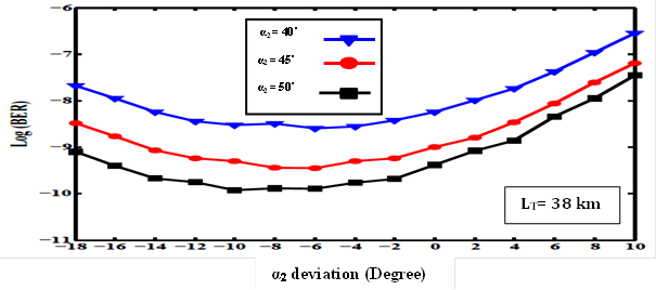
 deviation for different values of
  for monocycle OOK signaling
 and
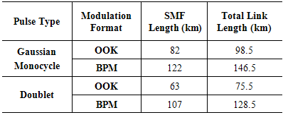
and  should be chosen carefully to minimize the BER for each of the four systems. This is a two-dimensional optimization problem and it is here performed for the four systems and for both types of the transmission links. Table 5 lists the optimum values of
  and
and  that give minimum BER. These results correspond to two transmission links, one consists of SMF while the other consists SMF and DCF with their optical amplifiers. The last column of this table lists the values of a performance measure parameter which is denoted by Figure of Merit (FoM)
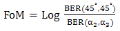
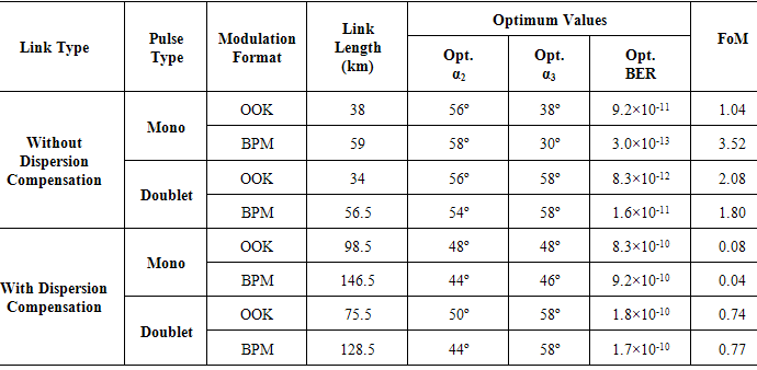
 on system performance. The results in Table 5 indicate clearly that BER performance can be enhanced by optimizing the rotation angles
  and
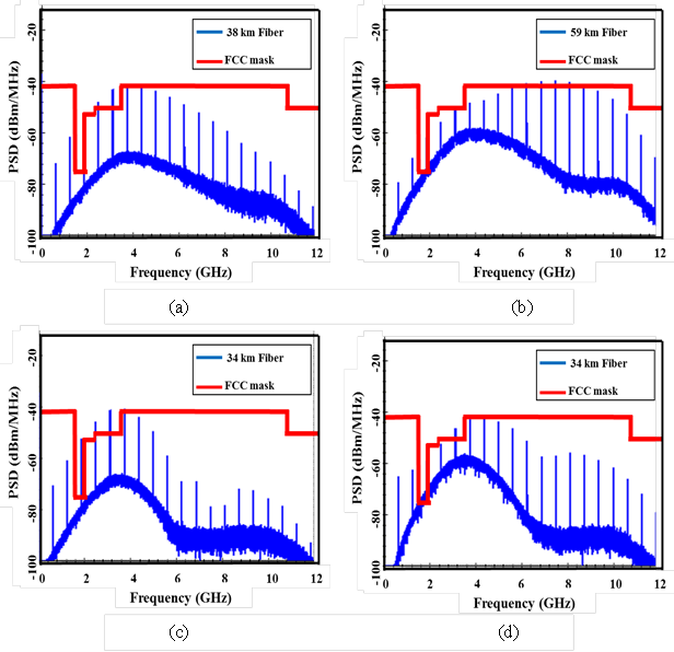
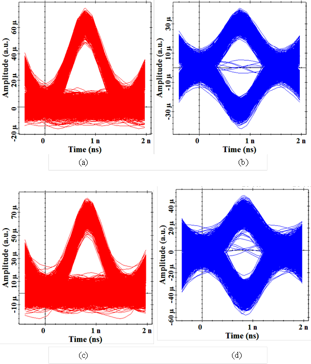
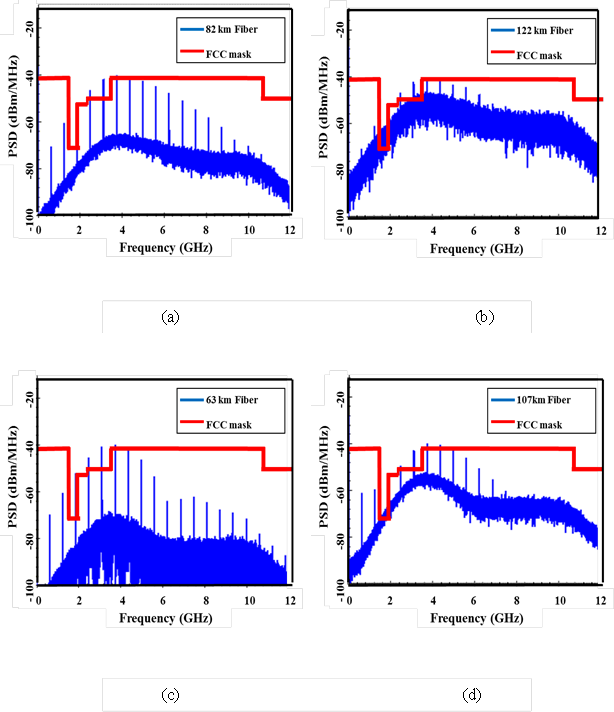
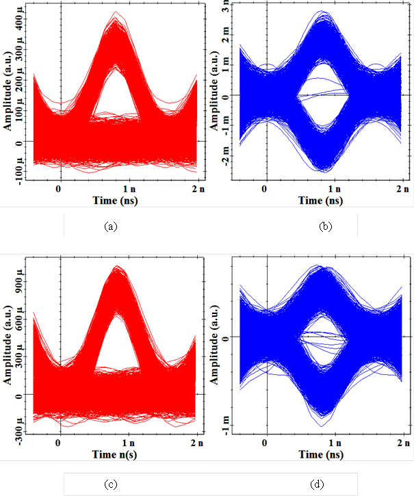
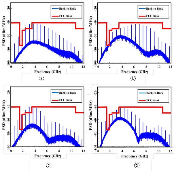
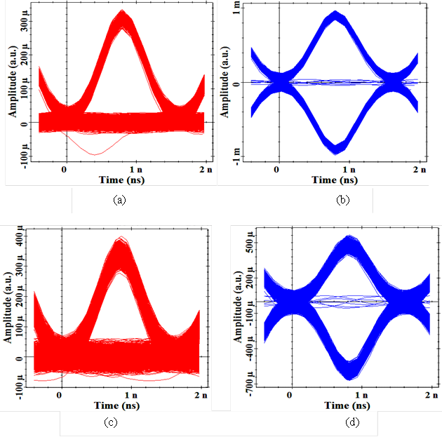
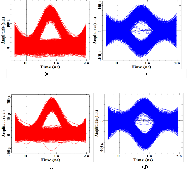
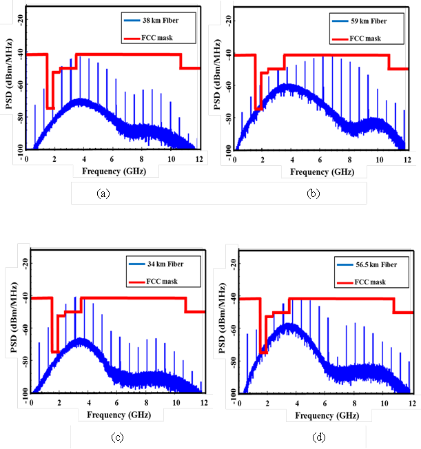
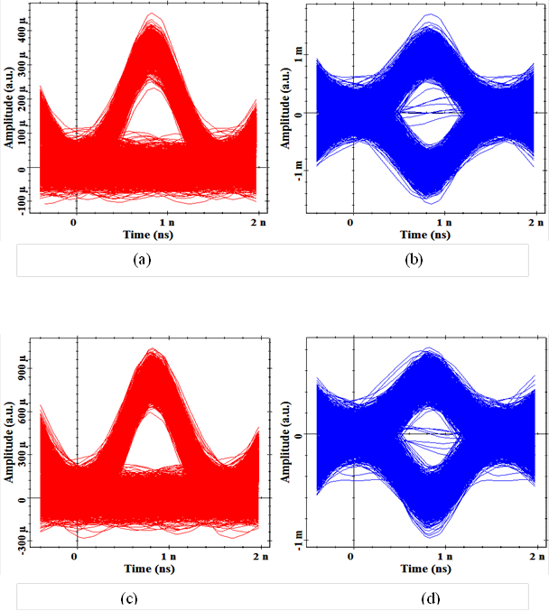
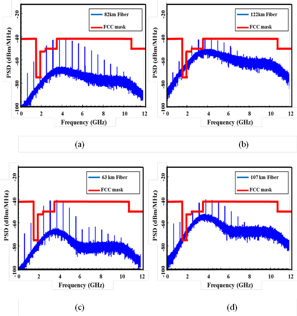
and  and this effect is more pronounced when the transmission link consists of a SMF only. The monocycle BPM system offers the best performance (FoM=3.52) when operates under optimum conditions. In contrast, the optimum rotation angles do not yield notable BER performance enhancement when the monocycle OOK and BPM system redesigned with fully loss and dispersion compensation.The corresponding optimum PSDs and optimum received eye diagrams are given in Figs. 13-16.