Samuel Ndueso John 1, Charles Uzoanya Ndujiuba 1, Veronica Ekaette Anthony-Michael 2, Chinonso Okereke 1
1Covenant University, Department of Electrical and Information Engineering, Ota, Nigeria
2National Open University of Nigeria, Department of Information Technology, Lagos, Nigeria
Correspondence to: Charles Uzoanya Ndujiuba , Covenant University, Department of Electrical and Information Engineering, Ota, Nigeria.
| Email: |  |
Copyright © 2015 Scientific & Academic Publishing. All Rights Reserved.
Abstract
With the increasing emphasis on service quality in the network of Airspace Management Agencyin the world, coupled with the extensive growth in internet traffic globally it has become a necessity to enhance the backbone network of Airspace Agency with flexibility of Internet Protocol using the Dense Wave Division Multiplexing (DWDM). This is to enhance the backbone network with a resilience of IP-DWDM in case of failure. The IP-DWDM network merges the IP and optical layers making network flexibility possible. The measurement, analysis and evaluations of the backbone network were carried out using simulation method. The throughput, latency and data loss were evaluated and analyzed. The result obtained shows that the Dense Wave Division Multiplexing has relatively high throughput, low latency and less packet drop which resulted in high transmission rate over a long distance and low cost in running the network. The paper therefore, proposes the use of embedded flexibility of the network in achieving an increase in the efficiency and utilization of the bandwidth of the interconnecting core routers of the networks.
Keywords:
IP, DWDM, Airspace, Antenna, Throughput, Packet Size
Cite this paper: Samuel Ndueso John , Charles Uzoanya Ndujiuba , Veronica Ekaette Anthony-Michael , Nonso Okerekle , Flexibility for Internet Protocol Backbone Network for Airspace Management Agency Using Dense Wave Division Multiplexing (DWDM), International Journal of Optics and Applications, Vol. 5 No. 1, 2015, pp. 1-9. doi: 10.5923/j.optics.20150501.01.
1. Introduction
The Nigerian Airspace Management Agency (NAMA) was established with a mandate to provide air navigation services that ensure safe, efficient, effective and economic flight operations [1]. In order to achieve her mission, the agency has the objectives of continuing to provide safe and functional air navigation services that will meet international standards; increasing air traffic control (ATC) capacity in order to manage the increasing air traffic volume and simultaneously reduce delays; and enhance the service quality. At present the agency makes use of VSAT technology to manage its signal/data communications which is a change from radio. The change from Radio to VSAT was necessary in order to enhance signal and data transmission across the Nation’s airports, thereby improving service delivery and safety. This was in order to get along with the rising global technological trend. Considering the rate of landing and takeoff of aircrafts from the Nigerian airports, there is need for effective communication with the pilots and proper management of Nigerian airspace by the air traffic controllers (ATC) across the airports in Nigeria. This cannot be achieved with the use of VSAT because of major limitations such as effect of sun transit, attenuation due to rain and direction of antenna among other factors.The Challenges of Sun TransitA sun outage, sun transit or sun fade is an interruption in or distortion of geostationary satellite signals caused by interference from solar radiation. The effect is due to the sun's radiation overwhelming the satellite signal. This is one of the problems that affect data and signal communication across the airports in Nigeria. The sun outage happens twice in a year for several minutes over a period of five or six days and this can result in air crash if the controller cannot communicate effectively with the other sites for better traffic [4]. The Challenges of Rain FadeThe most reliable satellite communications technology can sometimes be out-matched by the forces of nature. It's a phenomenon known as rain fade or rain attenuation - a weakening of the satellite signal as it passes through raindrops [4]. Any satellite communications system network operating in Ku-Band (12/14 GHz or higher frequencies) will face the effects of rain fade at some time. These different reactions ultimately have the same effect - they cause any satellite system to lose some of its normal signal level. Rain outage will only occur during the heaviest rains with only a small portion of the transmission path experiencing attenuation. It was discovered that the VSAT network used by NAMA fails in the months of May to August due to the effect of rain fade. These are months of heavy rain fall in the country (Nigeria). This phenomenon obstructs the total systems in TRACON (Terminal Radar Approach Control).The Challenges of Antenna DepointingThis may happen as a result of severe mechanical constraints on the antenna reflector, resulting from meteorological events such as strong winds (storms, hurricanes) or heavy snowfall, where wet snow or ice accumulates on the dish [4].To overcome these challenges, NAMA neededa more resilient and robust network infrastructure to reduce failure and promote future expansion. This paper aims at proposing DWDM to provide additional capacity to the existing fibres, in order to achieve good quality of service in the Nigerian airspace. This will enhance data transmission and communication performance across the Nigerian airports by providing flexibility for NAMA IP backbone networks.Dense Wavelength Division Multiplexing (DWDM)Dense wave division multiplexing (DWDM) is a fiber-optic transmission technique that employs light wavelengths to transmit data parallel-by-bit or serial-by-character. DWDM permits the implementation of Ultra-high-capacity transmission links. It is a technology that puts data from different sources together on an optical fiber, with each signal carried at the same time on its own separate light wavelength [2]. Using DWDM, up to 80 separate wavelengths or channels of data can be multiplexed into a light-stream transmitted on a single optical fiber. Each channel carries a time division multiplexed (TDM) signal. In a system with each channel carrying 2.5 Gbps (billion bits per second), up to 200 billion bits can be delivered per second by the optical fiber. Because each channel is de-multiplexed at the end of the transmission back into the original source, different data formats being transmitted at different data rates can be transmitted together. Specifically, Internet Protocol (IP) data, Synchronous Optical Network data (SONET), and asynchronous transfer mode (ATM) data can all be travelling at the same time within the optical fiber [3]. Apart from Bandwidth multiplication, DWDM's most compelling technical advantages can be summarized as follows: v Scalability—DWDM can leverage on the abundance of dark fiber in many metropolitan area and enterprise networks to quickly meet demand for capacity on point-to-point links and on spans of existing SONET/SDH rings. v Transparency—Because DWDM is physical layer architecture, it can transparently support both TDM and data formats such as ATM, Gigabit Ethernet, ESCON and Fibre Channel with open interfaces over a common physical layer. v Dynamic provisioning—Fast, simple, and dynamic provisioning of network connections give providers the ability to provide high-bandwidth services in days rather than months. DWDM is similar to wavelength-division multiplexing (WDM). The difference between WDM and DWDM is fundamentally one of only degree. DWDM spaces the wavelengths more closely than does WDM, and therefore has a greater overall capacity. The confines of this spacing are not precisely known, and have probably not been reached, though systems are available with a capacity of 128 channels (i.e., wavelengths) on one fiber.As the capacity of systems grow and with technologies advancing, allowing closer spacing and higher numbers of wavelengths DWDM is poised to provide the bandwidth for large amounts of data, moving beyond transport to become the basis of all-optical networking with wavelength provisioning and mesh-based protection [5].DWDM performed on an optical fiber serves as the underlying carrier for the optical network. The narrow channel spacing of about 1nm characterizes the system. Figure 1 depicts the general structure of the DWDM system. The Erbium doped Fiber Amplifier (EDFA), Multiplexer and the De-multiplexer form the vital blocks of the system. 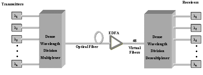 | Figure 1. Block Diagram of a DWDM System |
The concepts of optical fiber transmission, loss control, packet switching, network topology and synchronization play a major role in deciding the throughput of the network.Optical TransmissionThe DWDM system has an important photonic layer, which is responsible for transmission of the optical data through the network. Transmission refers to the conversion of electronic data (bits) to information in the form of light waves and sending it through the fiber. In the case of IP over DWDM, raw packets are converted into light and sent over photons. This layer is governed by various parameters [6].• Channel SpacingThe minimum frequency separation between two different multiplexed signals is known as the Channel spacing. Since the wavelength of operation is inversely proportional to the frequency, a corresponding difference is introduced in the wavelength of each signal. There exists a bound on the channel spacing. The optical amplifier's operational bandwidth & the receiver's capability to identify two close wavelengths are major factors introducing the bound. They restrict the number of unique wavelengths passing through the amplifier. Taking into consideration the above two factors, the international bodies have established a spacing of 100GHz to be the worldwide standard for DWDM. This means that the frequency of each signal is different from the rest by at least 0.1THz. The frequency is converted appropriately before multiplexing, based on the channel vacancy in the DWDM system. • Signal DirectionAn optical fiber helps transmit signal in both directions. Based on this feature, a DWDM system can be implemented in two ways – Unidirectional and Bi-directional. The choice is made based on the availability of fiber and the required bandwidth. The former brings in the need for a secondary fiber line and the latter reduces the capacity of the system. [6]DWDM System ComponentsImportant components of a DWDM system are the Add/Drop Multiplexer (ADM) and the Optical Cross Connect (OXC). The Add/Drop Multiplexer selectively adds/drops wavelengths without having to use any SONET/SDH terminal equipment. We require the ADM to add new wavelengths to the network or to drop some wavelengths at their terminating points. There are two types of implementations of the ADM, the Fixed WADM and the Reconfigurable ADM. When a system is configured with simple mux/demux devices such as the design in Figure 2 [7].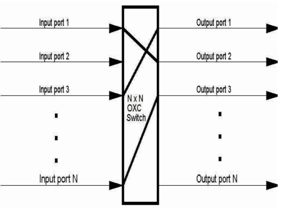 | Figure 2. Block diagram of the optical cross connects (OXC), which may be a MEMS device or waveguides [7] |
The Optical Cross Connect acts as a cross-connect between n-input ports and n-output ports. It allows the efficient network management of wavelengths at the optical layer. The varieties of functions that it provides are signal monitoring, restoration, provisioning and grooming. An optical network consists of wavelength routers and end nodes that are connected by links in pairs. The wavelength-routing switches or routing nodes are interconnected by optical fibers. Although each link can support many signals, it is necessary that the signals be of distinct wavelengths. Routers transmit signals on the same wavelength on which they are received. An All-Optical wavelength–routed network is that wavelength-routed network that carries data across from one access station to another without any O/E (Optical/Electronic) conversions [7], [8].Ethics of Backbone Network FlexibilityBackbone flexibility covers many aspects of both the physical and functional characteristics of a network e.g., at the physical level, there may be two different paths between a pair of distinct point of presence (Pops), providing route diversity of the fiber-optic transmission facilities. In the event of a failure situated between the nodes that terminate the path, a route still remains between the end-points. At the functional level meanwhile, possess certain capability (i.e. ‘resilience functionality’) that enables traffic between the designated end-points to be redirected from the primary route to an alternative route [9] as shown in Figure 3.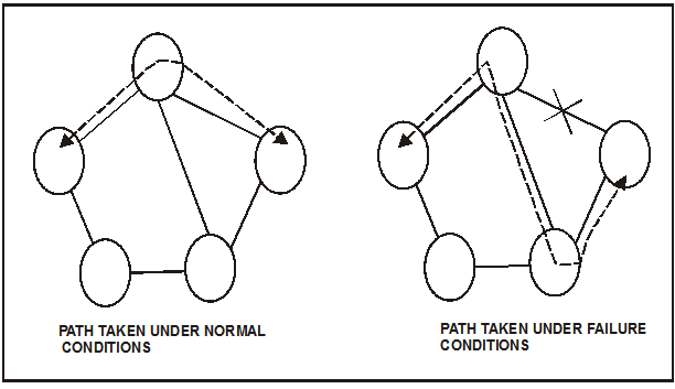 | Figure 3. Abstract view of network flexibility |
Advancement to IP-DWDM Over the past five years or so, there has been a steady migration of transmission architectures used to underpin IP backbone links, with ATM, SDH and DWDM being the principal technologies of interest. [8]Figure 4 shows the general trend from multilayer IP-ATM-SDH-DWDM architecture to IP-DWDM architecture. SDH and DWDM can be considered ‘layer 1 ‘transmission technologies, while ATM and Point-to-Point Protocol (PPP) are ‘Layer 2’ technologies. Multi-Protocol Label Switching (MPLS) combines features of Layer 2 technologies like ATM and Layer 3 technologies like IP, so is often referred to as Layer 2.5 [7], thereby increasing integrated transmission network architecture for IP backbones.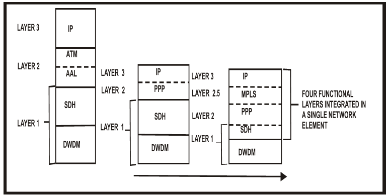 | Figure 4. Increasing integrated transmission network architecture for IP backbones |
IP-DWDM Reference ArchitectureThere are many kinds of optical transmission equipment that involve dense wave division multiplexing. DWDM systems allow multiplexing of a number of optical signals at different wavelengths onto a single optical fibre. By far, the most common is a DWDM multiplexer or line termination equipment (LTE). Such devices provide Point-to-point transmission between two locations. Typical systems allow 16 or 32 wavelengths.Figure 5 shows the reference architecture. IP core routers with optical interfaces will be interconnected to Dense Wave Division Multiplexer (DWDM) equipment via a transponder device. Transponders perform the function of translating a standard optical signal (normally at 1330 nm) from a router line card to one of several wavelengths as handled by the Dense Wave Division Multiplexer (DWDM) equipment. [3].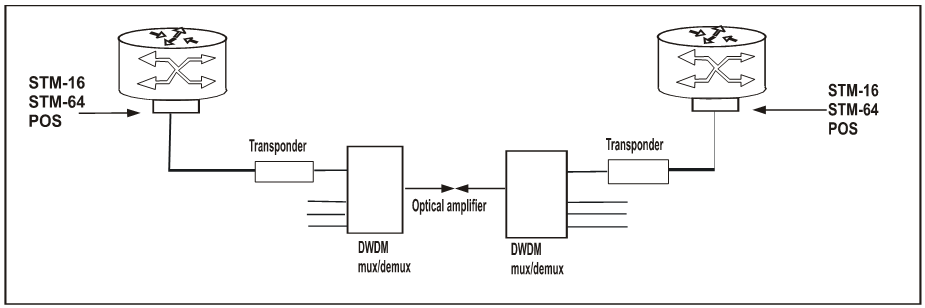 | Figure 5. Reference IP-DWDM architecture |
There are three distinct approaches to achieving resilience in an IP-DWDM backbone architecture, namely unprotected circuits, protected circuits and MPLS-based [8].For better insight and analysis, the following were compared between VSAT and DWDM characteristics; signal transmission capacity, band width management, throughput, latency, transparency, packet drop rate, efficiency, running and maintenance cost, etc. These comparisons were necessary to help in evaluating and arriving at the conclusions on resilience in an IP-DWDM architecture.This research work restricts its focus to VSAT and IP based DWDM schemes.
2. Methodology Measurement, Analysis and Evaluations
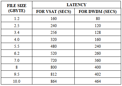
For this research work the following approaches were adopted.• The use of a File size download calculator was applied to simulate and estimate file download and transfer speed, noting the performance of DWDM as compared to that of VSAT.• The maximum throughput of the communication links was measured in a WAN network between the TRACON site of the Muritala Mohammed International Airport Lagos, and Aminu Kano International Airport Kano, using the Net Cracker professional software to simulate the WAN scenario and the effect of varying file sizes across the WAN link from a server to a remote desktop computer.• The third method in this research work was to take accurate readings for throughput, bandwidth, latency and noting the CPU performance as well as user voice and video experience on a network running on DWDM as compared with VSAT. This was carried out in four different cities on the network during the peak period for aircraft traffic in the Nigerian airspace, for a consecutive duration of six working days.• The fourth was to test the user’s perception when copying large files and making concurrent calls across WAN link. The following tools were used for the experiment:i. Catalyst 6506 core router: The Catalyst 6500 is a modular chassis network switch manufactured by Cisco Systems since 1999, capable of delivering speeds of up to "400 million packets per second “the 6506 is one of the catalyst models. [10]ii. Cisco voice over IP box: Voice over IP (VoIP) defines a way to carry voice calls over an IP network including the digitization and packetizing of the voice streams [10].iii. Windows trouble-shooting commands. iv. Cisco command: This simply describes the commands used to enter and exit the various Cisco IOS configuration command modes [10].v. File size download calculator: A simple calculator with which you can calculate download time for a file depending on download speed. How long time it will take depends on file size, your own download speed and the server's upload speed [11].vi. Whatsup Gold: WhatsUp Gold offers network, system, application and log monitoring and management in both physical and virtual infrastructure environments.LatencyLatency is the amount of time a message takes to traverse a system. [12]. It is calculated using the formula: Latency affects applications such as video conferencing, telephony, and game, data backup and multimedia service [12].BandwidthBandwidth refers to the data rate supported by a network connection or interface. One most commonly expresses bandwidth in terms of Bandwidth is determined by the physical limitation of the media e.g. Fiber, VSAT, DSL, or Cable Technology. It is also limited by the data link layer characteristics of the specific media in use e.g. Ethernet 10Mbps, Fast Ethernet 100Mbps, Gigabit Ethernet 1000Mbps. [13].ThroughputThroughput is the amount of data transferred from one place to another or processed in a specified amount of time. Data transfer rates for disk drives and networks are measured in terms of throughput. Typically, throughputs are measured in kbps, Mbps and Gbps. [17]Throughput = file size/Total Latency (bits/sec)Packet Drop RatePacket drop rate and out-of-order packets constitutes nuisance when supporting typical data applications like files and e-mail, will cause severe problem for critical applications like: data replication, backup and other disaster recovery functions across the network.. The slightest amount of packet loss has huge effect on a Backbone network and the problem gets worse as the amount of traffic increases across the WAN link [18],[19].Experiments and Results on Real NetworkThe experiment conducted was aimed at determining the throughput, latency and traffic pattern for both DWDM and VSAT network for various packet and file sizes and then analyse and compare the results.Experiment on the Various File Sizes Sent from the Server in the Lagos Airport to a Client in Kano Airport through the Vsat and DwdmThe various file sizes are 1.2Gb, 2.5Gb, 3.4Gb, 4.0Gb, 5.5Gb, 6.2Gb, 7.0Gb, 8.0Gb, 9.5Gb, 10.0Gb using the DWDM and VSAT network as captured in Table 1.
Table 1. Various file sizes and the download time for the networks
 |
| |
|
File Size and Latency Various file sizes and the download time for the networks.Analysis 1From Figure 6 and Table 2 we see that for a file size of 3.4GB, the transfer rate for VSAT is 256 seconds, but for DWDM it is 128 seconds. Again, for a file size of 9.5 GB, the transfer rate of VSAT is 812 seconds, while that of DWDM is 402 seconds. Since throughput is the amount of data transferred from one place to another or processed in a specified amount of time, it can be observed that DWDM transfers data faster than VSAT. Therefore, it can be deduced that DWDM has low latency compared to the VSAT network, when the various file sizes were used.Packet Drop Rate and Throughput for Both networks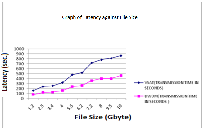 | Figure 6. Graph of Latency against File Size |
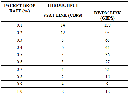
Table 2. Data on packet-drop-rate and throughput for VSAT and DWDM
 |
| |
|
Analysis 2From Figure 7, it can be observed that there is a decrease in Throughput as packet-drop-rate increases thus showing that DWDM has better throughput than VSAT link across the network.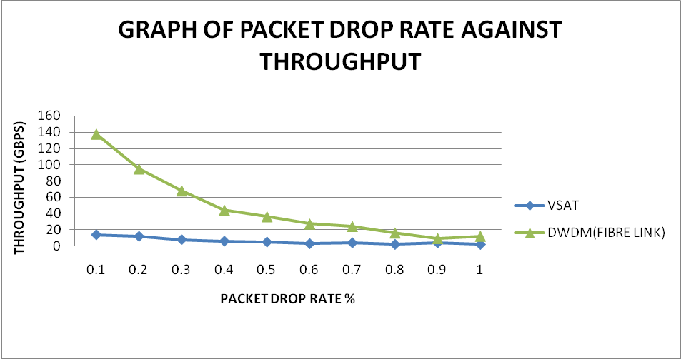 | Figure 7. Graph showing the effect of packet drop rate on throughput |
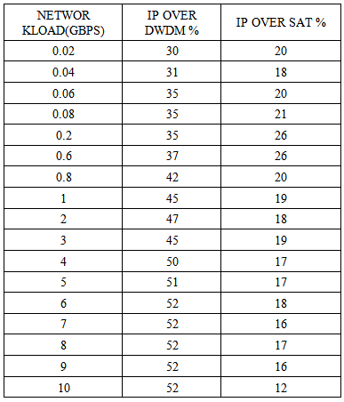
Experiment Showing the Capital Expenditure in Using VSAT Network and DWDM between Lagos Airport and the Kano AirportThe experiment was carried out between the TRACON site of the Lagos International airport and the Kano airport. The base offered load of the network was 1.6Gbps. Analysis 3From Figure 8, it is observed that at higher network loads, the IP-over VSAT architecture achieves 5 to 10 percent savings while the IP-over-DWDM architecture consistently achieves savings of approximately 50 percent. This implies that with the use of DWDM the throughput will be high with much capital expenditure savings.Table 3. Capital expenditures savings as a Function of Offered Load on the VSAT and the DWDM in the Lagos Airport
 |
| |
|
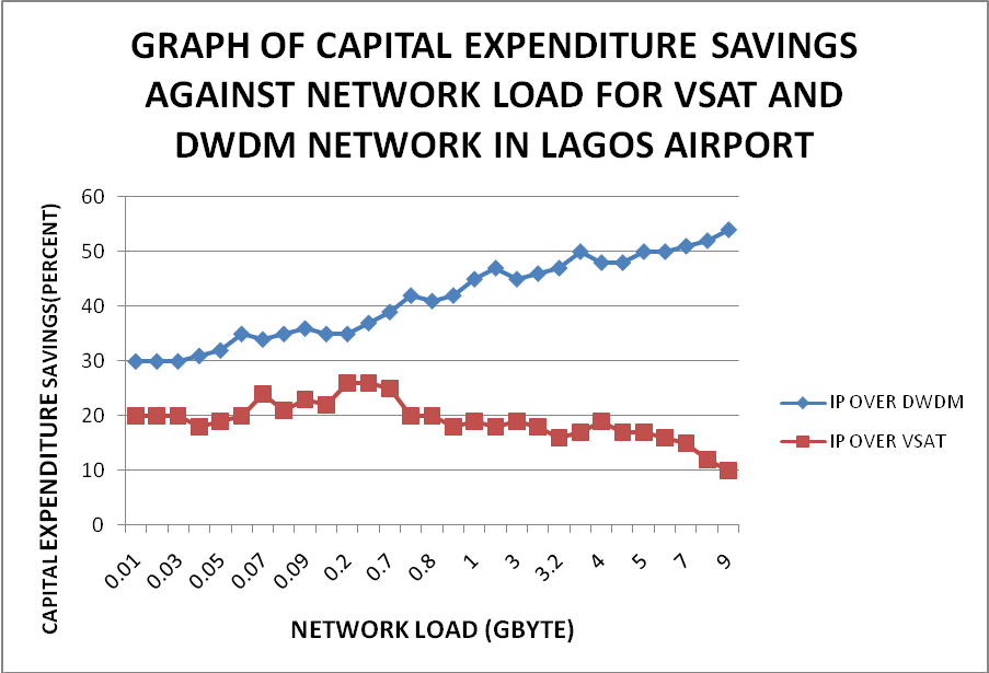 | Figure 8. Graph of capital expenditures savings against network load for VSAT and DWDM |
3. Results
The result of the experiment shows that the DWDM has very high throughput with higher bandwidth and very low latency and packet drop rate as compared with VSAT. It also has higher transmission and lower cost in running the network when put.
4. Conclusions
This project has explored alternative approaches to providing resilience to serious failures in IP backbone networks based on IP-DWDM architecture. The responsibility for protection and resilience from all possible faults lies with the IP routers. Although dynamic routing protocols such as Intermediate System-to-Intermediate System protocol (IS-IS) and Border Gateway Protocol (BGP) can re-converge from fault events. With the results obtained, it shows that DWDM has better network stability and resilience. These provides higher network capacity and less prone to failure because of the features it has, which enables it to withstand breakdown thereby proving it to be more reliable than VSAT. It is less prone to transmission impairments, faster and more economical to manage. All these translate to higher efficiency, effectiveness and network stability in the total radar coverage of Nigerian Airspace. The simulated experiment and life experiment carried out in this research work showed that Throughput, efficiency and the cost of running remote network can be greatly improved if DWDM is implemented in the airspace. The DWDM technology can be achieved by allowing aggregation of multiple logical transmission links, or ‘circuits’ onto a single strand of optical-fibre cable.
References
| [1] | "Nigerian Airspace Management Agency", Nigerian Airspace Management Agency. N.p.,n.d. Web. 15 Sept. 2014. <http://www.nama.gov.ng/>. |
| [2] | Krauss Ottmar: DWDM and Optical Networks: An Introduction to Terabit Technology. Erlangen Publicis Corporate Publishing, 2002. |
| [3] | J.D. Ash, S.P. Ferguson. "The evolution of the telecommunications transport architecture: from megabit/s to terabit/s." Electronics & Communications Engineering Journal 13.1 (2001): 33. |
| [4] | Maral, Gérard. VSAT networks. Chichester, West Sussex, England: Wiley & Sons, 1995. |
| [5] | Gumaste Ashwin, Tony Antony: DWDM Network Designs and Engineering Solutions. Cisco: Cisco press, 2003. |
| [6] | "IP over DWDM." IP over DWDM.N. p.,n.d. Web. 15 Sept. 2014.<http://www.cse.wustl.edu/~jain/cis788-99/ftp/ip_dwdm/index.html>. |
| [7] | D. Awduche, J. Malcolm, J. Mcmanus, J. Agogbua, M. Dell: Requirements for traffic engineering over MPLS. N/A: Requests for Comments 2072, 1999. |
| [8] | A.N. Viswanathan, Feldman, Z. Wang, R. Callon: "Evolution of multiprotocol label switching", IEEE Communications Magazine 36.5 (1998): 165-173. |
| [9] | Callegati Franco, Giorgio Corazza, Carla Raffaelli: "An Optical Packet Switch with a Multi-stage Buffer for IP Traffic." Optical Networking. London: Springer London, 1991. 300-311. Print. |
| [10] | "Cisco Catalyst 6500 Series Supervisor Engine 720 - Products & Services." Cisco. N.p.,n.d. Web. 16 Sept. 2014. http://www.cisco.com/en/US/products/hw/modules/ps2797/ps5138/index.html. |
| [11] | "Download time." Download Time Calculator. N.p., n.d. Web. 16 Sept. 2014. <http://www.download-time.com/>. |
| [12] | A. Savoia: "Web Page Response Time 101: Understanding and measuring performance test results." STQE Magazine Spring 2001: 48-53. |
| [13] | B.A. Usievich, V.A. Sychugov, O. Parriaux, J.Kh Nurligareev:" A narrow-band optical filter based on Fabry-Perot interferometer with one waveguide” grating mirror." Quantum Electronics 33.8 (2003): 695-698. |
| [14] | G.P. Agrawal: Fiber-optic communication systems. 2nd ed. New York: Wiley, 1997. |
| [15] | Ismail Mohdt Naziri, Adullah MohdZin: "Evaluation of software Network Analyser Prototyping using Qualitative approach." European Journal of Science Research 26.3 (2009): 170-182. |
| [16] | Molyneaux, Lan: The Art of application performance testing. Newton, Massachusetts, O Reilly Media, 2009. |
| [17] | D. J. Kruglinski: “Development Program Visual C++”, (Washington, Microsoft Press, 1999). |
| [18] | M.B. Pearce, I. Jacobs, J.H. Lee, J.K. Shaw: "Optimal input Gaussian pulse width for transmission in dispersive nonlinear fibers", JOSA B, Optical Society of America, Vol. 16, Issue 8, pp. 1189-1196, 1999. |
| [19] | J. ASH, S.P. FERGUSON: The evolution of the telecommunications transport architecture from megabit/s to terabit/s, Electron. Comm. Eng. J., February 2001, 13, (1), pp.33-42. |
 Abstract
 Reference
 Full-Text PDF
 Full-text HTML