-
Paper Information
- Paper Submission
-
Journal Information
- About This Journal
- Editorial Board
- Current Issue
- Archive
- Author Guidelines
- Contact Us
International Journal of Optics and Applications
p-ISSN: 2168-5053 e-ISSN: 2168-5061
2014; 4(3): 69-75
doi:10.5923/j.optics.20140403.01
A Constant Current Source for an External Cavity Diode Laser
 Abstract
 Reference
 Full-Text PDF
 Full-text HTML
Wesley Bor Kipkemoi1, Geoffrey Kihara Rurimo2, Dominic B. Onyango Konditi3
1Department of Air Traffic Services, Kenya Civil Aviation Authority, P.O Box 30163-00100, Nairobi, Kenya
2Department of Physics, Jomo Kenyatta University of Agriculture and Technology, P.O Box 62000-00200, Nairobi, Kenya
3Department of Electrical and Communication Engineering, Multimedia University of Kenya, P.O Box 15653-00503, Nairobi, Kenya
Correspondence to: Geoffrey Kihara Rurimo, Department of Physics, Jomo Kenyatta University of Agriculture and Technology, P.O Box 62000-00200, Nairobi, Kenya.
| Email: |  |
Copyright © 2014 Scientific & Academic Publishing. All Rights Reserved.
A constant current source suitable for running a Diode Laser is presented. The electronic circuit comprises of a loop filter circuit and a couple of transistors. The loop filter circuit is divided into three cascaded subsections namely: the filter input, augmenting integrator, and the voltage divider network. Current fluctuations as low as 0.5% were measured for a Laser Diode operating at maximum current of 140 mA. These are small enough to endanger a Diode Laser life. The designed driver circuit was used to study the power and voltage variations versus current for a Diode Laser. This was also extended to operate an External Cavity Diode Laser (ECDL) with no observed mode hops. This is an indication of the constant nature of the driving current.
Keywords: Diode Laser, Linewidth, Constant current, Optical spectrum
Cite this paper: Wesley Bor Kipkemoi, Geoffrey Kihara Rurimo, Dominic B. Onyango Konditi, A Constant Current Source for an External Cavity Diode Laser, International Journal of Optics and Applications, Vol. 4 No. 3, 2014, pp. 69-75. doi: 10.5923/j.optics.20140403.01.
Article Outline
1. Introduction
- Diode Lasers fall into the category of Semiconductor Lasers. Their operation is based on a semiconductor gain medium, where optical gain is achieved by stimulated emission at an inter-band transition under conditions of a population inversion (i.e., high carrier density in the conduction band, compared with the valence band) [1, 2]. Without pumping, most of the electrons are in the valence band. A pump beam with photon energy above the band gap energy can excite electrons into a higher state in the conduction band, from where they decay to states near the bottom of the conduction band. At the same time, the generated holes in the valence band move to the top of the valence band. Electrons in the conduction band can then recombine with these holes, emitting photons with energy near the band gap energy. This process can also be stimulated by incoming photons with suitable energy [3]. Advances in Diode Laser design strongly depend on fabrication technologies. Liquid Phase Epitaxy (LPE) is one of the common fabrication technologies that is used to fabricate simple configurations of Diode Lasers [4]. Laser performance is limited by the inability of LPE to grow uniform thin epitaxial layers and accurately tailored doping profiles that result in low power output of a Diode Laser. The first technology improvement necessary for the realization of high power Diode Lasers was the development of two new growth technologies namely: Metal Oxide Chemical Vapour Deposition (MOCVD) and Molecular Beam Epitaxy (MBE) [4]. These two key technologies produced a powerful tool that enables the Laser designer to control the crystal growth to an atomic scale. As a result, uniform material deposition has been used to grow even quantum well active layers [5]. The first experiment on Diode Laser coupled to an external cavity was demonstrated in 1964 [6] just after the first successful operation of a Diode Laser in 1962. External Cavity Diode Lasers (ECDLs) were studied in the early and late 1970s by a couple of research groups in Russia [7, 8]. Flaming and Mooradian published the first paper on the properties of ECDLs in details [9]. Considerable works were done from the early to mid-1980s at British Telecom research Laboratory, motivated by the prospect of applying External Cavity Diode Lasers as a transmitter and local oscillator in coherent optical telecommunications [10]. In the same time a lot of research has been done also at American Telephone and Telegraphic (AT&T) Bell laboratories in US and Center of National d’Etudes des Telecommunications (CNET) in Spain. Recently Diode Lasers have been widely used in the scientific research and engineering technology [11, 12]. Their application in spectroscopy which is the fundamental study of the interaction between matter and photons especially in atomic physics have been extensively studied [13, 14]. Its application in optical fiber telecommunication as a local oscillator and coherent transmitter source has been soaring in the recent years [15]. Other applications include; injection seeding, Second harmonic generation, Metrology, Gas monitoring, and Light-wave testing and monitoring [16].
2. Tunable External Cavity Diode Laser
- A tuneable External Cavity Diode Laser (ECDL) comprises a Diode Laser chip (an optical gain medium) with antireflection coating on one or both facets and optics for coupling the output of the gain medium to the free space of the external cavity. An ECDL uses a diffraction grating as the wavelength-selective element in the External resonator. As a result, they are also called grating-stabilized Diode Lasers. A common ECDL is the Littrow configuration [17, 18] which contains a collimating lens and a diffraction grating as the end mirror. In this configuration, the first-order diffracted beam provides the optical feedback to the Diode Laser chip, which has an anti-reflection coating. The emission wavelength can be tuned by rotating the diffraction grating. A disadvantage of this tuning process is that, the direction of the output beam changes. In the Littman–Metcalf configuration [19], the grating orientation is fixed, and an additional mirror is used to reflect the first-order beam back to the Laser diode. The wavelength can be tuned by rotating that mirror. This is used to reflect the first-order beam back to the Diode Laser. The wavelength can be tuned by rotating that mirror. This configuration offers a fixed direction of the output beam, and therefor most preferred.
3. The Constant Current Driver Circuit
- The semiconductor Laser chip is a device with high-power density and its ability to withstand the impact of current is poor. Small changes in driving current normally lead to great changes in optical output power and device lasing wavelength. These changes are undesirable and they can endanger the safe use of the semiconductor laser.In practical running of Diode Lasers, a constant current is needed for its performance and the protection of the semiconductor Laser chip. A Constant Current type circuit will vary the voltage to maintain constant current regardless of load impedance which is appropriate ac loads. A constant current driver circuit for the Diode Laser was designed and implemented. This circuit comprises of a loop filter circuit as the major component followed by a pair of transistors. The following section discusses this major component.
3.1. The Loop Filter Circuit
- The constant current driver circuit incorporates a loop filter as the major component as shown in Figure (1). The loop filter circuit is divided into three cascaded subsections namely: the filter input, the augmenting integrator, and the voltage divider network as shown in Figure 1.The two major functions of the loop filter is to remove any noise or high frequency components present in the input signal. The primary function of the filter input subsection is to convert the output of the zener diode into a single ended signal for subsequent processing by the integrator circuitry. Appropriate values for the current setting resistors (R4 and R5, in figure 2) must be ascertained. The goal in choosing these resistor values is to maximize the gain of the filter input subsection while ensuring the output transistors operate in active mode.
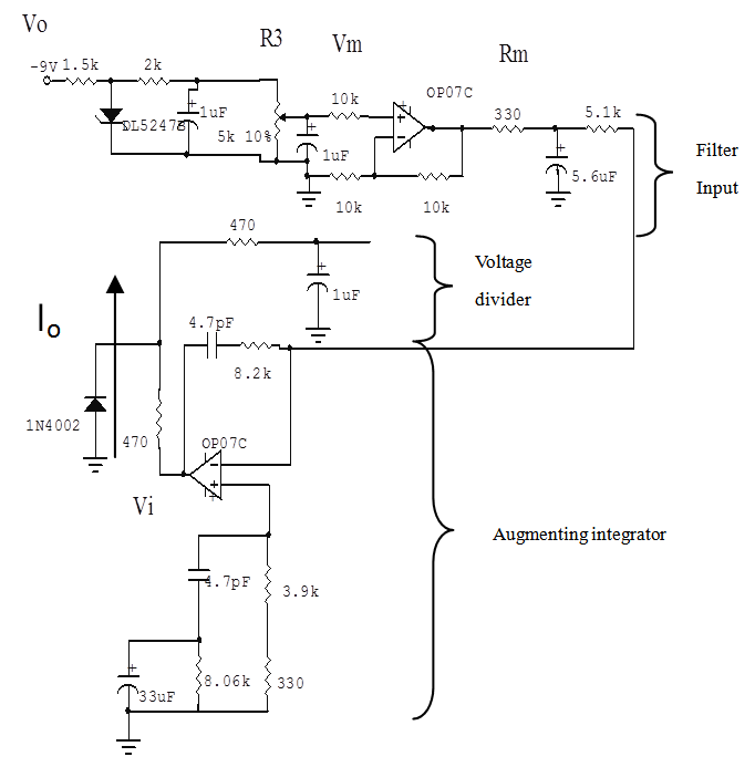 | Figure 1. Loop Filter circuit, showing the filter input, the augmenting integrator and voltage divider circuits |
3.2. The Operation of the Constant Current Circuit
- The constant current circuit incorporates a loop filter and a pair of transistors as shown in Figure 2.
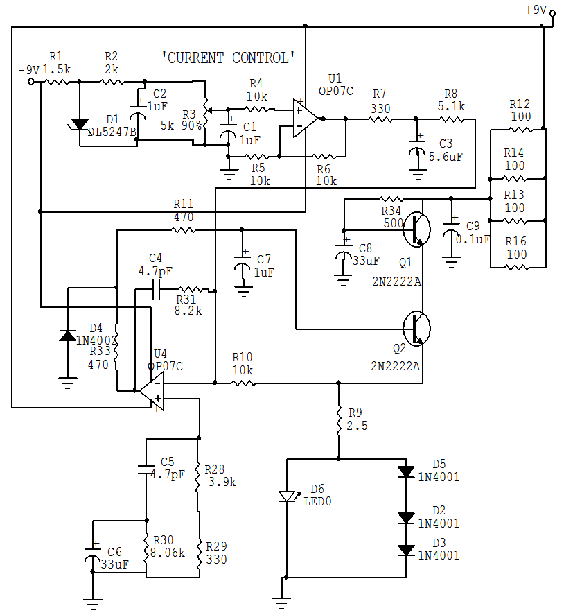 | Figure 2. Constant current driver circuit for the external cavity diode Laser |
4. Experimental Results
- In this section, experimental results demonstrating a constant current supplied by the electronic driver circuit are presented. The fabricated driver circuit is used to drive an External Cavity Diode Laser. Results are presented as well indicating a mode hope free operation which can be an indication of a characteristic stable current driver circuit.
4.1. The Stability of the Current I0 for the Diode Laser
- The current I0 is influenced remarkably by a change in the load resistance. The stability of the current for load changes was tested by measuring the current I0 using a combiscope. The results are presented in fig. 3(a)–(d) for different values of currents. The current stability was calculated from the peak to peak voltage behaviour. Fig. 3(a) refers to the graph with no current input. This shows a fluctuation of peak to peak voltage of 233mV and this value is taken as the reference voltage. With current injected into the circuit, the peak to peak voltage for the different current values as in figures 3(b)–(d) remained stable at 240mV. The difference in voltage, i.e. (240-233) mV gives the driver peak to peak voltage value. Using ohms law V=IR, and the Laser Diode resistance of 10Ω calculated from the current-voltage relationship measured experimentally; Then, I = 0.0007 A = 0.7 mA. This translates to about 0.5% fluctuation from the Laser diode rated current of 140 mA, thus small enough to affect the Laser Diode performance.
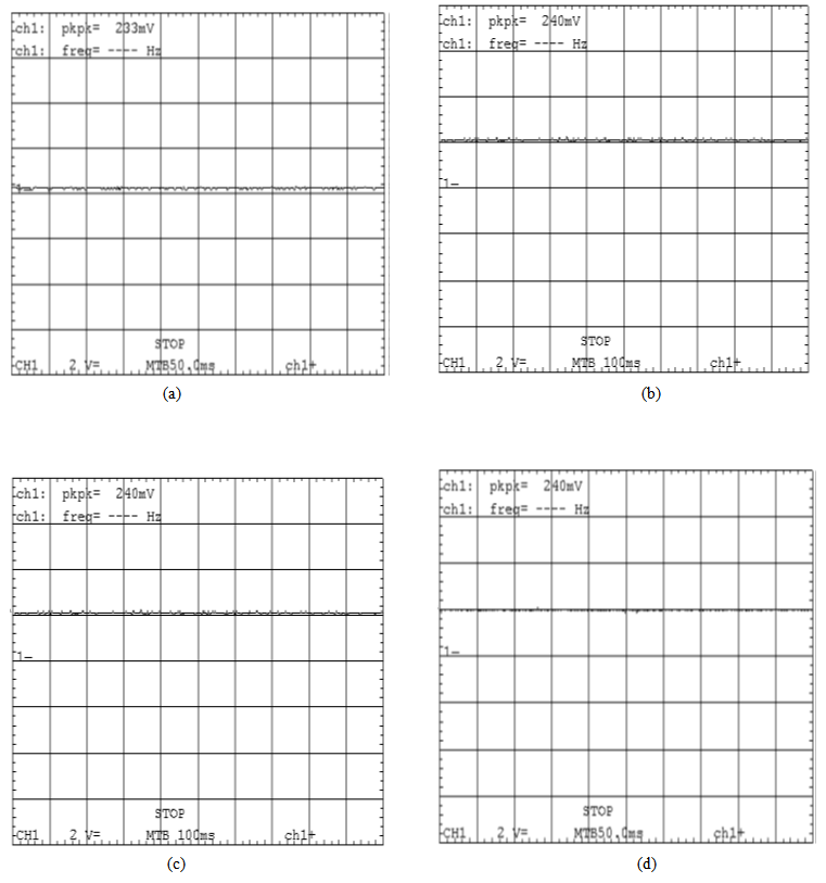 | Figure 3. Stable current measurements showing noise levels at different currents: (a). At 0 mA (b). At 42.1 mA (c). At 93.7 mA (d). At 112.1 mA |
4.2. Laser Diode Power and Voltage Variation Versus Current
- The Laser Diode output power versus current characteristic is shown in Figure 4. It is a plot of the measured power from the Laser Diode against the applied driving current.
 | Figure 4. A plot of the relationship between Laser Diode output power and the applied driving current |
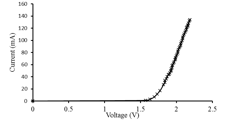 | Figure 5. Current versus Voltage curve |
4.3. The Tuneability of the External Cavity Diode Laser
- The constructed Constant current source was used to run a Diode Laser with and without an External Cavity. By adjusting the current and measuring the output power of the Diode Laser for each increment, a threshold current of 46 mA was measured. This is the current for which the Laser Diode gain satisfies the lasing condition. Below the threshold current very little light is emitted by the Laser structure and the carrier density is proportional to the injection current. Once the Laser diode begins to oscillate, the carrier density is clamped at the threshold value.To measure the spectrum of the Laser diode, its output was coupled into a multi-mode fiber connected to a Spectrum Analyzer. The easiest way to align the fiber more precisely is by directing the output of the other end of the fiber on a white surface. When the fiber is correctly positioned the light through the fiber is quite bright, and one can easily use the fiber to illuminate a nearby object. An alternative would be to use a power meter and maximize the output from the fiber.When the fiber was aligned, the output end was screwed into the spectrum analyzer. Without the External Cavity, the linewidth of the emitted spectrum at FWHM was measured as 2.3 nm. This value reduced to approximately 1.9 nm when running the Diode Laser on an External Cavity. Hence the External Cavity configuration serves to narrow the linewidth of the emitted spectrum. The wavelength resolution of the spectrum analyser was set at the smallest value of 1nm. It was noted that, a current of 115 mA gave rise to a much stable and wider tunable range of the Laser Diode. Hence all the measurements were recorded at this current value. The spectral curves for the measured wavelengths were then plotted as shown in Figure 6(a)–(d).In single longitudinal mode lasers, tuning effects cause what is commonly referred to as “mode hopping.” Not only does the position of these mode hops vary from device to device, but a temperature dependent hysteresis also occurs. Mode hopping can be very difficult to deal with. Three factors that determine the mode hopping characteristics of a particular Diode Laser includes: Cavity Length, Input Current and Optical Feedback.In this experiment the input current was held constant and the temperature change, which is undesirable, was eliminated. Our device demonstrated a stable power for the various tunable modes with very minimal signs of mode hoping with time.The non-symmetrical intensity profiles suggest that the External Cavity Diode Laser was running on multimode. The resolution of the spectrum analyzer is not sufficient to resolve the different frequency components and this causes the the asymmetry and hence the broadening of the intensity profiles in figures 6(a)–(d). As the wavelength is tuned, the modes assume different powers giving rise to the asymmetry. However, the intensity profiles remain stable when the Laser is running.
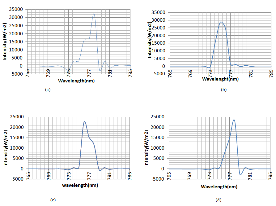 | Figure 6. (a). Optical spectrum without the external cavity, (b). 775.3 nm, (c). 776.3 nm and (d). 777.7 nm |
5. Conclusions
- We have constructed an External Cavity Diode Laser based on Littman mount configuration, which demonstrated the ability to produce a tunable, collimated beam of light with a continuous tuning range of 3 nm while providing 32 mW power.After designing the driver circuit using the Circuit Maker software, it was possible to transfer the schematic to a printed circuit board; hence we were able to come up with a small and compact driver circuit. Analogue circuits used for the Laser Diode were assembled using operation amplifiers and other electronic components. The main function of each component was studied and the driver characteristics were measured and the respective graphs plotted. The circuit demonstrated the ability to supply a constant and stable current as the calculated fluctuation of 0.5% is too minimal to affect operation of the Laser Diode; this was a paramount achievement since diode lasers are easily damaged by unstable currents and voltages.The acquired spectral graphs for this system showed no signs of Mode hopping. This is an important achievement since mode hopping can cause problems in laser applications; In telecommunications, for example, the switching from one mode to another affects the maximum data transmission rate, because different wavelengths have different velocities in single-mode fibre with high dispersion. Spectroscopy is another area that usually requires wavelength stability. Semiconductor lasers find a wide range of applications due to their variety of wavelengths, compact size, low price and ease of control. Unfortunately, mechanical tuning was found to be slow in the ECDL configuration, and it was difficult to achieve high wavelength tuning speed, and good reproducibility. In order to overcome these problems, it is suggested that instead of moving the mirror mechanically, the wavelength of laser can be tuned electronically.
ACKNOWLEDGEMENTS
- This research work was conducted at Jomo Kenyatta University of Agriculture and Technology Optics and Lasers Research Laboratory.