-
Paper Information
- Previous Paper
- Paper Submission
-
Journal Information
- About This Journal
- Editorial Board
- Current Issue
- Archive
- Author Guidelines
- Contact Us
International Journal of Optics and Applications
p-ISSN: 2168-5053 e-ISSN: 2168-5061
2014; 4(2): 62-67
doi:10.5923/j.optics.20140402.06
A Revisit of Refractive Index Profiles Design for Reduction of Positive Dispersion, Splice Loss, and Enhancement of Negative Dispersion in Optical Transmission Lines
 Abstract
 Reference
 Full-Text PDF
 Full-text HTML
Faramarz E. Seraji, Razieh Kiaee
Optical Communication Group, Iran Telecom Research Center, Tehran, Iran
Correspondence to: Faramarz E. Seraji, Optical Communication Group, Iran Telecom Research Center, Tehran, Iran.
| Email: |  |
Copyright © 2014 Scientific & Academic Publishing. All Rights Reserved.
Loss and dispersion are two crucial parameters to be determined as low as possible while designing optical fibers as optical transmission lines. In designing dispersion shifted fibers, one has to reduce the core diameter to smaller than unshifted single mode fiber (USMF) at 1550 nm wavelength region. This issue causes the nonlinear phenomenon of four wave mixing (FWM) to appear at 1550 nm. One of the approaches to reduce the effectiveness of the FWM is to shift the zero dispersion wavelength (ZDW) to some other wavelength in the third window of optical fiber communication. Dispersion compensating fibers (DCFs) with high negative dispersion are used in wavelength division multiplexing systems for neutralization of pulse spread in transmission fibers for higher system capacity. One of the approaches of securing a high negative dispersion is to change the refractive index profile of DCFs. In this paper, by using Optifiber software, the shifting of the ZDW is made by varying the refractive index profile of a USMF, then the designed profile is optimized for low dispersion and splice loss. The obtained results show that in designed profile the effective mode field diameter is reduced, which can effectively reduce the splice loss. In another attempt, the parameters of different DCF profiles are optimized to enhance negative dispersion of about -710 ps/nm.km, which is 5 times higher than the reported experimental results.
Keywords: Optimization, Positive and negative dispersions, Refractive index profiles
Cite this paper: Faramarz E. Seraji, Razieh Kiaee, A Revisit of Refractive Index Profiles Design for Reduction of Positive Dispersion, Splice Loss, and Enhancement of Negative Dispersion in Optical Transmission Lines, International Journal of Optics and Applications, Vol. 4 No. 2, 2014, pp. 62-67. doi: 10.5923/j.optics.20140402.06.
Article Outline
1. Introduction
- Unshifted single mode fibers (USMF) have minimum dispersion in 1300 nm optical window, while at 1550 nm window the dispersion is at highest level and the attenuation is at lowest value. Meanwhile, for longest transmission distance, the dispersion and the attenuation should be at minimum values. To achieve this condition, one has to shift the minimum dispersion of 1300 nm window in to the 1550 nm window [1, 2]. One of the approaches is to reduce considerably the diameter of a USMF so as to develop a dispersion shifted fiber (DSF). On the other hand, the reduction of diameter can cause nonlinear phenomenon of four wave mixing (FWM) at 1550 nm. To nullify this effect, the zero dispersion should be shifted to some other wavelengths in the 1550 nm region [3].In past two decades, the employment of optical fibers in long haul transmission lines of high bit rates used in WDM systems, has made the control of the pulse broadening caused by dipersion phenomenon, an essential task for design engineers to tackle with [4]. To neutralize this phenomenon to an accepted level, the use of DCFs is recommended that are now being marketed for commercial uses. These fibers are capable of creating high negative dispersion to confront the positive dispersion, which is the cause of pulse broadening while propagating through optical fibers [5]. Since 1990, different types of DCFs have been designed and developed with commercial qualities, and till date the designers are puting efforts to maximize the negative dispersion values of the DCFs [6-17].In this paper, a triangular profile of a DSF with a zero dispersion wavelength (ZDW) at 1550 nm is considered as a starting sample profile [1]. First, by manipulating the profile, the ZDW is shifted to another wavelength within third optical communication window. Then, by using Optifiber software [18], the profile is optimized for reduction of positive dispersion and splice losses [19, 20]. To manage the dispersion of the transmission fiber, the parameters of refractive index profile and effective area of a single-mode fiber [21] are optimized to enhance the negative dispersion, while keeping the macrobending loss at low level.
2. Design of Transmission Fiber
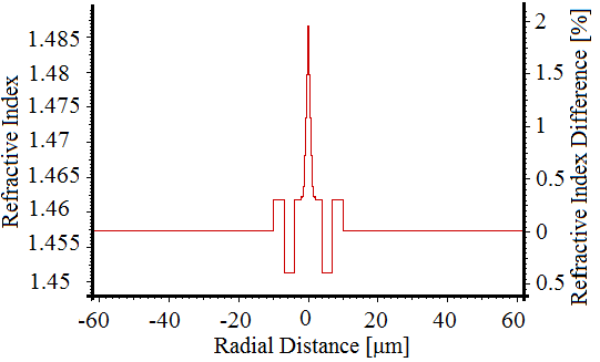
- The transmission fibers used in optical communication systems should have positive dispersion as low as possible in third optical communication window. The aim of this analysis is to optimize the positive dispersion of the dispersion shifted fiber (DSF) with a triangular profile, having a dispersion value of 10 ps/nm.km and ZDW value of 1550 nm [1]. Figure (1), which is designed by Optifiber software, shows the triangular profile, which consists of four index regions. The region 1, has a radius of 3.1 μm, with refractive index changing linearly from 1.44692 to 1.4615. The cladding is divided into three regions 2, 3, and 4 with different radius of 1.32, 1.5, and 56.58 μm, respectively. The index of the ring in the cladding region is 1.450. In total, the diameter of the fiber is 125μm.
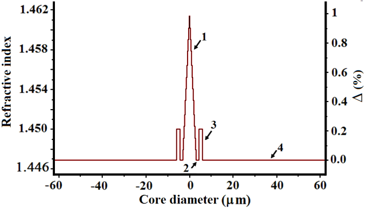 | Figure (1). Profile of DSF with triangular refractive index |
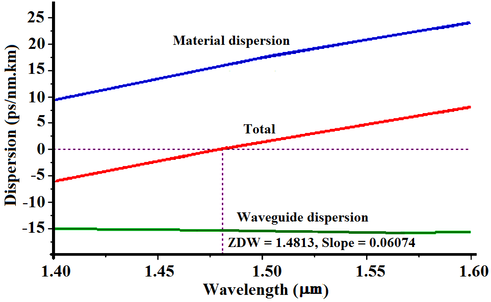
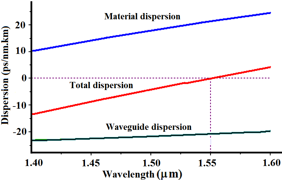 | Figure (2). Dispersions of the DSF as a function of wavelength |
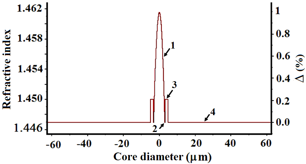 | Figure (3). Gaussian profile |
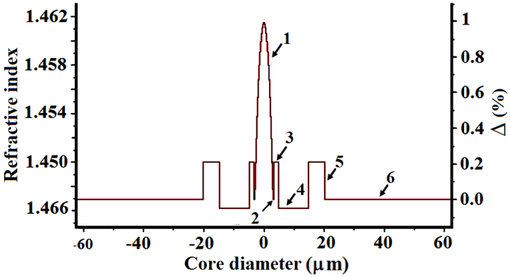 | Figure (4). Optimized two-ring Gaussian core profile |
 | Figure (5). Dispersion of the optimized two-ring Gaussian core profile |
3. Result and Discussions
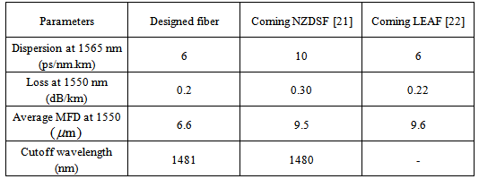
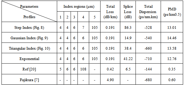
- The dispersion of the optimized two-ring Gaussian core profile is plotted in Fig. (5). The macrobending loss and total attenuation of the optimized designed profile are illustrated in Figs. (6) and (7), respectively. In this fiber, the ZDW is shifted to 1.4813 μm where the dispersion, dispersion slope, microbending loss, and total attenuation are 4.74 ps/nm.km, 0.06074 ps/nm2.km, 0.002 dB/km, and 0.20 dB/km, at 1550 nm respectively. The macrobending loss in the wavelength range 1.4 to 1.6 μm is ideally almost negligible. The designed profile is comparable with the NZDSF product already marketed [21]. A Comparison of designed parameters with reported references is presented in Table 1.
|
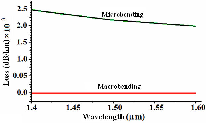 | Figure (6). Bending loss of fiber with two-ring Gaussian profile in terms of wavelength |
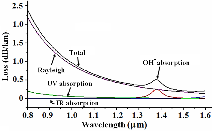 | Figure (7). Total attenuation of fiber with two-ring Gaussian profile in terms of wavelength |
4. Design of DCFs
- To achieve a high negative dispersion in DCFs with high effective core area and a low macrobending loss, it is required that parameters of the refractive index profile be suitably changed in such a way to ensure the single-mode operation of the fiber, while keeping effective core area at higher level [20]. In this section, three types of profile geometries, namely, step index, triangular index, and exponential index are suggested for DCFs. The modeling and design procedues are dealth with the suggested profile configurations as follows.
4.1. Step Index Profile
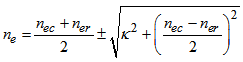
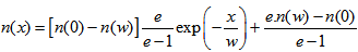
- Based on a single-mode fiber DCF, a profile of DCF with five index regions are proposed, as shown in Fig. 8. The effective index profile of combined core and cladding regions is built up by the following expression [20], using OptioFiber software [18]:
 | (1) |
 is the effective index of the core,
  denotes the effective index of the ring regions, and
  is the coupling strength between core and cladding modes.The designed core consists of two regions. The central region has diameter of 4 μm with a refractive index of 1.4859. The second region has width of 2 μm with an index of 1.4618. The total core diameter is 8 μm. The cladding is divided into two major inner and outer regions. The inner region is further subdivided in two regions. The innermost region has 6 μm with a reduced index of 1.4514. The reduction of the index is obtained by adding 1% Fluorine to the silica material of the cladding. The second inner region has the same width of 6 μm and its index is at the same level of second region of the core, i.e., 1.4618.The outer region of the cladding is made 105 μm wide with an index of 1.4573. In total, the fiber diameter is 125 μm, which is a standard value of optical fiber used in optical communication systems.
 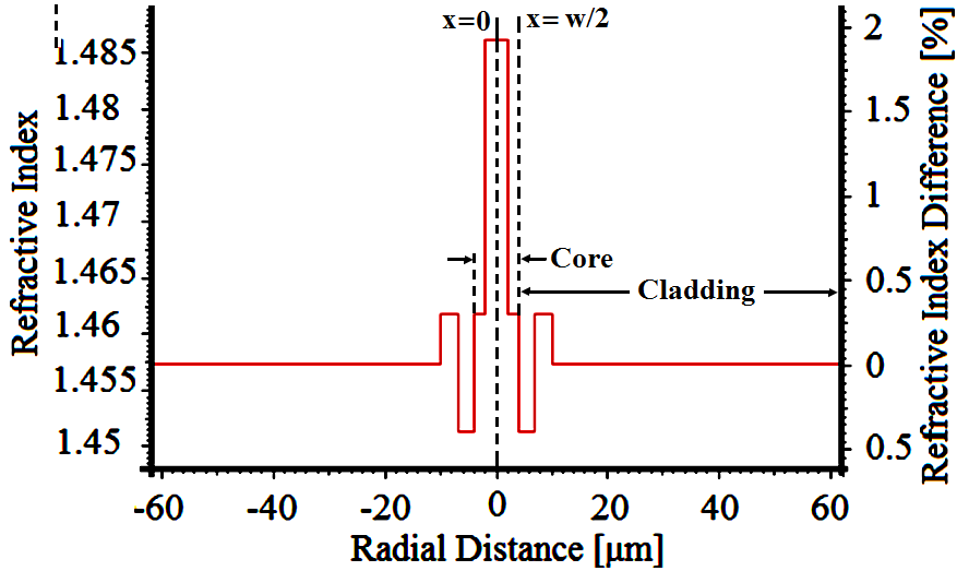 | Figure (8). Step refractive index profile of DCF |
4.2. Triangular Index Profile
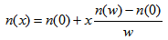
- With the same parameters as of Fig. 8, the central core region is converted from step index to triangular profile by the following expression [23]:
 | (2) |
 is the local coordinate of the core region, indicates the width of the ring,
  and
and  are the refractive indices at
  and
and  , respectively. The profile is depicted in Fig. 9.
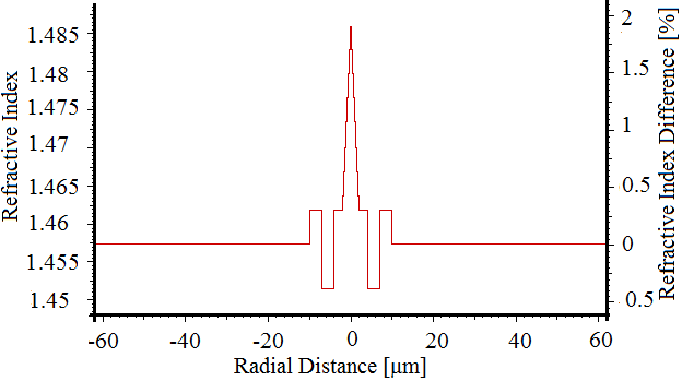 | Figure (9). Triangular refractive index profile of DCF |
4.3. Exponential Index Profile
- By using the same parameters of last two cases and employing the following index model, we obtain a exponential index as shown in Fig. 10. [18]:
 | (3) |
 | Figure (10). Exponential refractive index profile of DCF |
4.4. Comparison of the DCF Designs
- All the proposed profiles have the same double-core index and two-ring indices in their cladding regions with equal dimensions. However, their core index shapes are different; step-, triangular-, and exponential-profiles. The height of the core index in all the profiles is 1.4859.In Ref [20], a triple-clad refractive index profile was proposed and the reported negative dispersion at 1550 nm wavelength was -144 ps/nm.km. In our design procedures, we proposed double-core DCFs for three types profiles of step-, triangular-, and exponential-index.In Figs. 11, the respective dispersions are plotted as a function of wavelength. In step index profile, the negative dispersion was enhanced to -528 ps/nm.km. For cases of triangular and exponential profile, even more negative dispersions have been achieved, i.e., -660 and -710 ps/nm.km, respectively, where in each case, waveguide, material, and total dispersion are depicted.
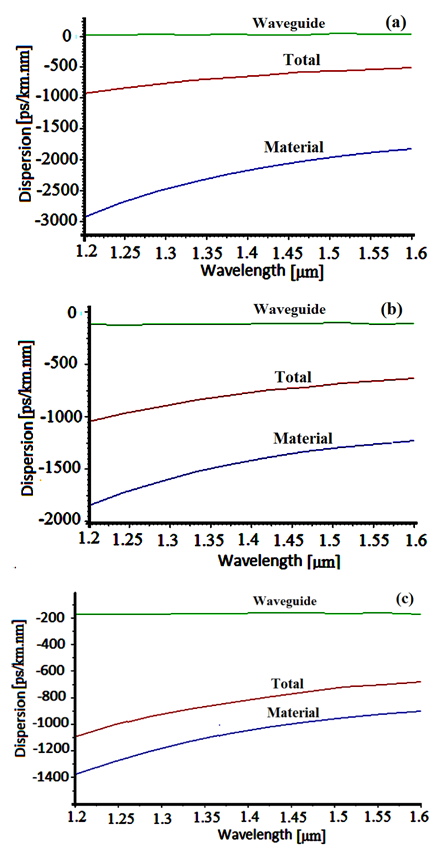 | Figure (11). Waveguide, material, and total dispersions of the designed DCFs in terms of wavelength. (a) Step index, (b) Triangular index, and (c) Exponential index |
|
5. Conclusions
- This paper revisited the design of refractive index profiles of transmission medium optical fiber to reduce the dispersion and mode field diameter, resulting in lowering of splice losses. A sample fabricated profile is chosen for modification its zero dispersion wavelength from 1550 nm to 1480 nm. Then by adding an engineered index ring in the inner cladding region of the profile, the dispersion and the loss have been reduced to 4.74 ps/nm.km and 0.20 dB/km, respectively. These values are comparable with the LEAF fiber already reported.In terms of mode field diameter, the obtained result shows reduction as compared with the commercially available fibers, thereby resulting in reduction of splice loss. The results of this analysis may be utilized by the designers of DSF/NZDSF in search of low mode field diameter and splice loss.To enhance the negative dispersion of DCFs, three types of refractive index profiles with double-core region are proposed. Step-, triangular-, and exponential-index variations have been selected for the central core regions. In all the cases, two rings, one positive and the other negative index with respect to silica base material are introduced in the inner cladding in the vicinity of the core. All the profile parameters have been optimized to obtain high negative dispersion, much higher than reported result in the literature. The obtained negative dispersion at 1550 nm wavelength are -528, -660, -710 ps/nm.km, from step-, triangular-, and exponential-index profiles, respectively. The highest obtained value is five times higher than the latest reported result.