-
Paper Information
- Next Paper
- Previous Paper
- Paper Submission
-
Journal Information
- About This Journal
- Editorial Board
- Current Issue
- Archive
- Author Guidelines
- Contact Us
International Journal of Optics and Applications
p-ISSN: 2168-5053 e-ISSN: 2168-5061
2014; 4(2): 40-45
doi:10.5923/j.optics.20140402.03
Design of Dispersion Compensating Fibers with High Negative Dispersion and Low Bending Loss: A Comparative Analysis
 Abstract
 Reference
 Full-Text PDF
 Full-text HTML
Faramarz E. Seraji, Jamshid Ahvati
Optical Communication Group, Iran Telecom Research, Tehran, Iran
Correspondence to: Faramarz E. Seraji, Optical Communication Group, Iran Telecom Research, Tehran, Iran.
| Email: |  |
Copyright © 2014 Scientific & Academic Publishing. All Rights Reserved.
The dispersion of optical pulses propagating in high speed WDM optical transmission systems is almost unavoidable. For a reasonable compensation of the dispersion, use of dispersion compensating fibers (DCF) is one of accepted approaches being practiced in past two decades. Due to their peculiar refractive index profile, the DCFs have relatively high attenuation when inserted as a device in a network. In this paper, by using the Optifiber software, four varieties of single-mode fibers of high compensating capabilities with a low bending losses are designed, optimized, and then compared with a fabricated sample developed by Fujikura Co. In an optimized design case, a negative dispersion of -517 ps/nm.km with a bending loss of 3.3 dB/km at bending radius of 20 mm is obtained.
Keywords: Negative dispersion, Macrobending loss, Dispersion compensating fibers
Cite this paper: Faramarz E. Seraji, Jamshid Ahvati, Design of Dispersion Compensating Fibers with High Negative Dispersion and Low Bending Loss: A Comparative Analysis, International Journal of Optics and Applications, Vol. 4 No. 2, 2014, pp. 40-45. doi: 10.5923/j.optics.20140402.03.
Article Outline
1. Introduction
- The increasing demand for high speed and high capacity optical transmission systems that resulted in introducing high speed wavelength division multiplexing (WDM) systems, has faced a detrimental phenomenon of dispersion causing spread in optical pulses that could constrain the bit rates and transmission capacities [1, 2].The effects of this phenomenon, namely, chromatic dispersion, reveals itself with a more pronounced in all the optical transmission systems working with a bit rate higher than 40 Gb/s [3-5]. There are several approaches to countermeasure and neutralize its destructive effects to a reasonable and acceptable level. One of suitable approaches is to use dispersion compensating fibers along the transmission line [6]. Since 1990 till date, these types of fibers have been suggested and some of them have been made commercially available for uses in long haul optical transmission systems [7-9]. Due to their peculiar refractive index profile that are different from transmission optical fibers, these fibers suffer a high bending loss. Therefore, their refractive indices should be designed for an optimized bending radius, suitable for installation in bending situation inside bent ducts and paths, etc. [10-12]. In recent years, photonic crystal fibers (PCF) have attracted the attention of designers of optical devices to develop high negative dispersion compensating fibers (DCF) to be used in long haul high bit rate optical transmission systems [13-17]. Theoretically, using PCFs seems one of promising approaches to achieve high negative dispersions. But manufacturing proposed complex structures of PCFs is not an easy task by present technology [18]. As of today, uses of conventional optical fiber profiles are common and experimented practices for design of DCFs [19-21].In this paper, referring to the refractive index profiles as of today [22, 23], four varieties of DCF profiles, namely, graded, triangular, step index with one ring, and step index with two rings are proposed.The proposed DCFs are investigated for parametric optimization towards high negative dispersion with low bending losses. With a best condition of optimization, a designed DCF for C-band of optical communication window, a negative dispersion of -517 ps/nm.km has been attained at a bending radius of 20 mm; bending loss was obtained as 3.3 dB/km, which is comparable with commercially available product reported in [22, 24].
2. Dispersion and Macrobending Loss
- It is well-known that chromatic dispersion causes pulse spread along the transmission line, resulting in constraining of transmission capacity in optical communication networks [25]. In this section, some fundamental expressions are provided to shed light on what basis the profile designs of DCFs are carried out by the Optifiber software. [26].Generally, dispersion in optical fiber is determined by the following expression [27]:
 | (1) |
 the optical wavelength,
  speed of light in a vacuum,
  angular optical wavelength, and
  is the propagation constant. The second derivative of propagation constant with respect to angular optical frequency is given by:
 | (2) |
 the effective core refractive index,.
  refractive index of cladding,
  is the relative refractive index difference between core and cladding and
  , and
, and  is the wave number in a vacuum.The total dispersion, due to material and waveguide dispersions, is obtained as [27]:
 | (3) |
 of transmission fiber is due to the bend radius
  , which is large compared to the fiber diameter and obtained as [28, 29]:
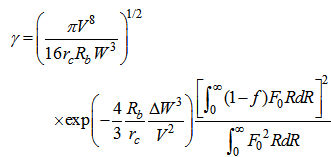 | (4) |
 radial field of fundamental mode,
  bending radius,
  fiber core radius,
  is the normalized frequency,
  and
and  are given as:
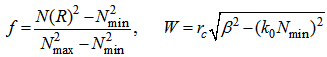 | (5) |
 refractive index profile,
  wave number in a vacuum,
  and
and  are the maximum and minimum refractive indices, respectively. The parameters
  and
and  are expressed as:
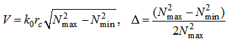 | (6) |
 is defined in dB/km as:
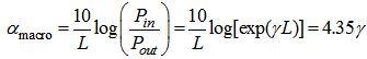 | (7) |
 is the length of transmission line in km,
  is the input power and
  indicated the output power at the end of transmission line.
 3. Design of DCF with Low Bending Loss
- Conventional single-mode fibers in C-band of optical communication have positive dispersion of about 18 ps/nm.km. The more the transmission distance, higher will be the dispersion effects on the transmitted pulses. To neutralize this phenomenon, design of dispersion compensating fiber (DCF) with negative dispersion seems to be an essential task [30, 31].To obtain a higher compensability of DCF with a least macrobending loss at an optimum bending radius around C-band of optical communication, we have suggested four profiles with graded, triangular, step (with one ring/two rings) variations of refractive indices. The four suggested profiles have depressed cladding with GeO2-doped and Fluorine-doped silica material used for core and cladding regions, respectively. Since DCFs are inserted as device in optical transmission lines, their geometrical parameters should match with transmission fibers so as to avoid splice losses [32]. Therefore, some parametric trade off should be made for design and optimization of DCFs structure. Thus in all our design samples of DCFs for compliance with optical transmission fiber used in optical communication systems, the core and cladding diameters are assumed to be 8 μm and 117 μm, respectively, and total fiber diameter is taken as 125 μm. The commercial Optifiber software is employed in all our design procedures [26].
3.1. Graded and Triangular Index Profiles with One Ring
- The DCF with a core of graded index profile of Gaussian shape as shown in Fig. 1(a), is designed using the following index profile model [26]:
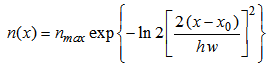 | (8) |
 is the maximum core index,
  is the local coordinate of the region,
  local peak position in graded core region,
  is normalized value of full width at half maximum (FWHM).For a triangular index profile, the following model is employed to design the proposed DCF, as shown in Fig. 1(b) [26]:
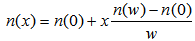 | (9) |
 is the width of the region,
  and
and  are the refractive indices at
  and
and  , respectively, and
  is the local coordinate in the core region.
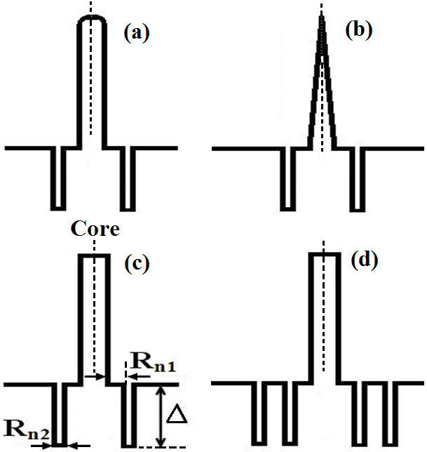 | Figure 1. Profiles of DCF. (a) Graded index with one ring, (b) Triangular index with one ring, (c) Step index with one ring, and (d) Step index with two rings |
3.2. Step Index Profile with One and Two Rings
- By doping the core region with a suitable constant amount of GeO2, a step index profile is designed and by adding 1% Fluorine to the inner cladding region, the ring region is formed, as shown in Fig. 1(c). The distance between the ring and the core is indicated as
 and the width of the ring is shown as
  , as shown in Fig. 1(c). The relative index difference between the core and the ring region is denoted as
  .By keeping the parameters values in the present one-ring step index profile, one more ring is made beside the previous ring to obtain two-ring step index profile, as illustrated in Fig. 1(d). For the analysis of dispersion values, linear polarized matrix method is used for fundamental mode LP01 [33, 34].
4. Dispersion Compensability of DCF
- To obtain maximum negative dispersion with minimum macrobending loss, the four designed profiles are optimized in two steps and then compared with each other. In the first step of optimization and comparison, the ratio of regions layers
 is increased with an increment of 0.01. The resulting dispersion variations of the four profiles are depicted in Fig. 2.
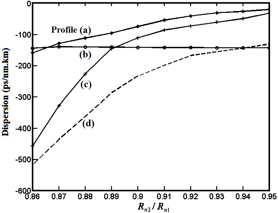 | Figure 2. Chromatic dispersion in terms of  for profiles (a, b, c, and d) of Fig. (1) at 1550 nm wavelength for profiles (a, b, c, and d) of Fig. (1) at 1550 nm wavelength |
 increases, the dispersion compensability of the designed DCFs reduces, i.e., the dispersion attains more positive values. As indicated, the slopes of dispersion variations in cases of step index profiles (with one/two rings), are steeper than two other cases. In addition, the effect of
  on the triangular profile is not considerable.In the second step of optimization and comparison of refractive index profiles in terms of dispersion compensability of DCFs, the effect of the relative refractive index difference
  between the core and the ring regions is analyzed and the results are shown in Fig. 3. In this case, in relation with the
  variations, the ring regions in step index profile are more effective than other two cases. Conceptually, one can note that the ring regions in step index profiles could help this effectiveness in negative dispersion values. Practically, the reason could be due to fundamental mode propagation through the inner cladding region which helps in more waveguide dispersion of negative nature [27].The results obtained in two steps of optimizations show that towards higher negative dispersion, the relative refractive index
  should be at maximum value while the ratio
  should be at its minimum level.
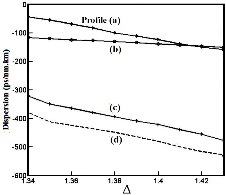 | Figure 3. Chromatic dispersion in terms of  for profiles (a, b, c, and d) of Fig. (1) at 1550 nm wavelength for profiles (a, b, c, and d) of Fig. (1) at 1550 nm wavelength |
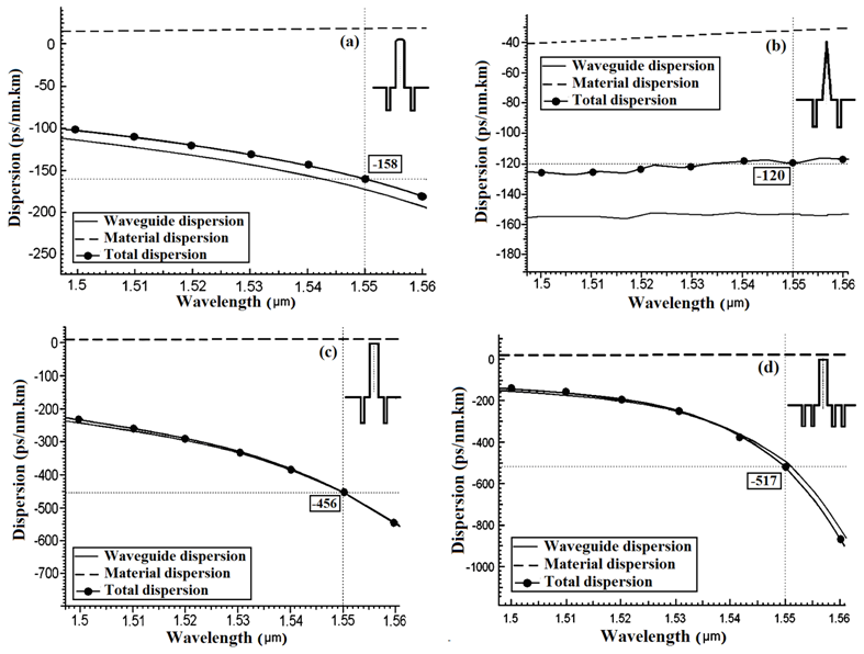 | Figure 4. Dispersion of the designed DCFs (a) Graded index, (b) Triangular index, (c) Step index with one ring region, and (d) Step index with two ring regions |
5. Analysis of Macrobending Losses
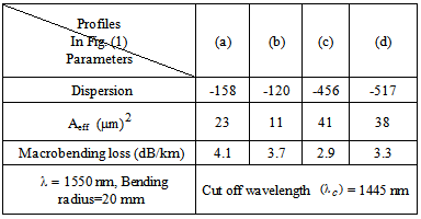
- The determination of macrobending loss of the four designed profiles of DCFs is based on Eq. (4) of Snyder-Love model [28]. Fig. 5 shows the results of the analysis of macrobending losses in terms of bending radius for different designed DCFs at 1550 nm wavelength. Based on the obtained results, as shown in Fig. (5), we note that the macrobending losses with bending radius of 20 mm for graded and triangular indices are 4.1 dB/km and 3.7 dB/km, respectively.
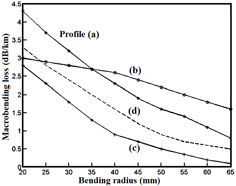 | Figure 5. Macrobending loss as a function of bending radius for different profiles of Fig. (1) at 1550 nm wavelength |
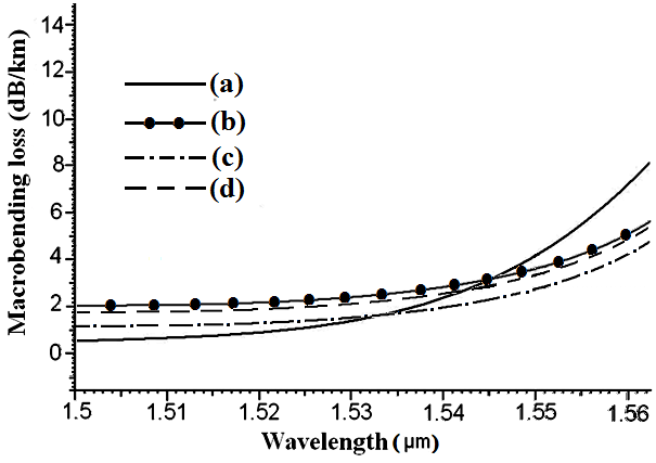 | Figure 6. Macrobending losses of the designed DCFs as a function of wavelength. (a) Graded index, (b) Triangular index, (c) Step index with one ring region, and (d) Step index with two ring regions |
|
6. Conclusions
- In this paper, we have proposed and analyzed four refractive index profiles for optimization of high negative dispersion compensating fibers with low macrobending losses. It is shown that to achieve a high negative dispersion DCFs with low macrobending losses, the ratio of width of ring regions in the inner cladding to the distance between the ring and the core
 should be at minimum and the relative refractive index difference between core and cladding regions
  should be at its higher value.A comparison of results of the analyses of different refractive index profiles of proposed DCFs show that highest negative dispersion, namely, -517 ps/nm.km, is achieved in the step index profile with two rings in the inner cladding. The lowest negative dispersion is achievable by a DCF with triangular index profile that was obtained as -120 ps/nm.km.The lowest macrobending loss among the four DCFs, is that of the one-ring step index profile with value of 2.9 dB/km.