-
Paper Information
- Paper Submission
-
Journal Information
- About This Journal
- Editorial Board
- Current Issue
- Archive
- Author Guidelines
- Contact Us
International Journal of Optics and Applications
p-ISSN: 2168-5053 e-ISSN: 2168-5061
2014; 4(1): 1-6
doi:10.5923/j.optics.20140401.01
A Grating Optical Filter with Angular Selectivity of the Directional Light Transmission
 Abstract
 Reference
 Full-Text PDF
 Full-text HTML
Rustam S. Zakirullin
Department of Heat and Gas Supply, Ventilation and Hydromechanics, Orenburg State University, Orenburg, 460018, Russian Federation
Correspondence to: Rustam S. Zakirullin, Department of Heat and Gas Supply, Ventilation and Hydromechanics, Orenburg State University, Orenburg, 460018, Russian Federation.
| Email: |  |
Copyright © 2012 Scientific & Academic Publishing. All Rights Reserved.
An optical filter with thin-film grating layers on both surfaces of the transparent sheet substrate is presented. The gratings are formed by absorptive, reflective, or scattering strips, alternating with directionally transmissive strips. Their relative position on input and output surfaces provides angular selectivity of the light transmission – part of the radiation that has passed through the input gratings is blocked additionally by the output gratings depending on incidence angle. A graphic-analytical calculation method determines the influence of geometric parameters of plane-parallel and coaxial-cylindrical filters on angular characteristics of transmission. At pre-known trajectory of light source relative to the filter pre-adapted angular selective regulation of its light transmission is provided. Architectural glazing to control the transmitted solar radiation without special redirecting devices is the most promising area of application.
Keywords: Optical filter, Gratings with alternating strips, Graphic-analytical calculation method, Angular selective regulation, Directional light transmission
Cite this paper: Rustam S. Zakirullin, A Grating Optical Filter with Angular Selectivity of the Directional Light Transmission, International Journal of Optics and Applications, Vol. 4 No. 1, 2014, pp. 1-6. doi: 10.5923/j.optics.20140401.01.
Article Outline
1. Introduction
- Classical thin-film multilayer filters are optically homogeneous in each layer of the surface coating. Inhomogeneous coatings with thin microporous scattering films[1], metal films with square holes[2], diffraction gratings[3] and photonic crystals[4] have been used in optical filters. All these surface and bulk inhomogeneities are on the micro- and nanoscales, consequently, the phenomena occurring in them belong to the subject matter of physical optics. Research has been carried out in order to improve the characteristics of filters designed to increase the angular tolerance[5] and, conversely, to apply the angular dependence of the transmission spectrum[6]. A single nanoslit in a metal film flanked by dielectric gratings has been proposed[7]. New possibilities for realization of narrow-band transmission filters have been introduced[8]. Some filters have adaptive properties[9, 10].In addition to the known matrix and recursive methods for the calculation of the reflection and transmission coefficients, a modular concept has been described[11]. Directional transmission from a single subwavelength slit in a metal film with periodic dielectric bars was analysed numerically[12]. Properties of the fenestration systems with Venetian blinds have been described by a bi-directional transmission distribution function[13]. Regulation of the directional light transmission of fenestration systems requires the use of additional devices. Smart glass of different types with thin- film coatings[14] and photochromic[15], electrochromic[16] and liquid crystal[17] layers have been used to change the spectral range and intensity of solar radiation. Polarization of the light has been used for invisibility achievement through a window at certain angles of observation[18]. Among all variety there are no optical filters transmitting only the demanded and preliminarily calculated part of incident radiation in different ranges of incidence angles. In this paper, a multilayer grating filter for angular selective regulation of directional light transmission without additional devices is presented. The filters of plane-parallel and coaxial- cylindrical forms are considered. The paper contains:1. Introduction2. Design of a plane-parallel filter 3. A graphic-analytical calculation method4. Dependence of the difference of offsets of refracted beams on the characteristic incidence angle5. Features of the calculation of a coaxial-cylindrical filter6. Potential applications of the filter 7. Conclusions
2. Design of a Plane-parallel Filter
- On both surfaces of a glass substrate the alternating transmissive and absorptive strips of millimetre and submillimetre widths are formed. Absorptive strips can be replaced with reflective or scattering stripes. The gratings formed by alternating strips are fundamentally different from diffraction gratings in size and purpose. Due to the dimensions of inhomogeneities on the surfaces, in contrast to[1–4], optical properties of the filter can be considered exclusively within geometrical optics. Accordingly, a method of calculation of its characteristics is simplified in comparison with the existing methods[11–13].Figure 1 presents the schematic diagram of a grating filter. On surfaces of a plane-parallel sheet substrate of the thickness s the transmissive (widths t1 and t3) and the absorptive (t2 and t4) parallel strips alternate. Like the period of diffraction gratings, the gratings are characterized by the step (repetition period) of the strips, that is, the total width of the two adjacent strips. The steps of the strips can be either equal (in Figure 1: t1+t2=t3+t4), or one period can be an integer multiply of the other (the multiplicity of steps is (t1+t2)/(t3+t4)). Shift of output gratings of the filter relative to input gratings is characterized by incidence angle of the beam passing through centres of the alternating strips. Characteristic angle
 is specified in Figure 1 – at incidence angle of 30o the beam passes through the centres of the transmissive strip on the input gratings and the absorptive strip on the output gratings after refraction at the angle
  Offset l30 of the refracted beam on the output surface with respect to the non-refracted beam at normal incidence angle and the length d30 of the path of the refracted beam through the filter glass are indicated.
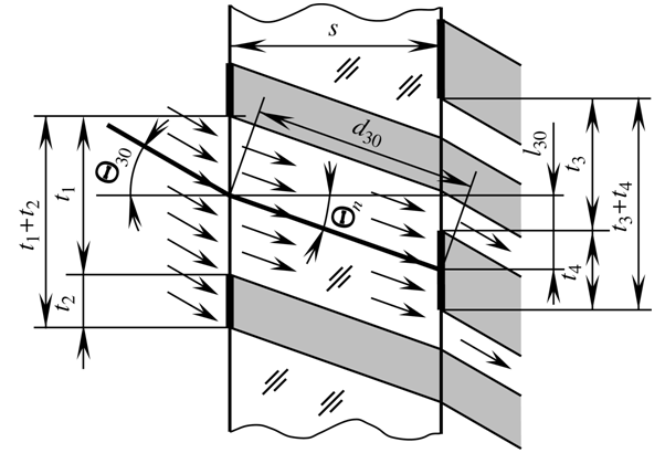 | Figure 1. The schematic diagram of light transmission of a grating filter |
3. A graphic-analytical Calculation Method
- The coefficient of light transmission is defined by a graphic-analytical calculation method[20]. In calculating the coefficient of light transmission
 of the plane-parallel filter for a given incidence angle
 the ratio of the areas considered in Section 2 can be replaced by the ratio of the widths of the strips:
 | (1) |
 | (2) |
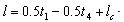
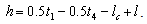
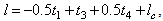
 refractive index n=1.5. The change in the width of light transmission was specified for the four angular ranges with identical characteristics. In the range of incidence angles from 0o to 14.22o the width of light transmission is reduced by equation:
 | (3) |
 | (4) |
 | (5) |
 | (6) |
 | (7) |
 | (8) |
 | (9) |
 | (10) |
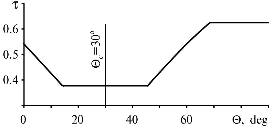 | Figure 2. The angular characteristic of the plane-parallel filter |
 and
and  respectively. At normal incidence the reflection coefficient is equal to
  i.e.
i.e.  For linearly polarized light with an azimuth
  of oscillations of incident wave the components of a vector of electric field are equal to
  At the azimuth
  will be
  hence, intensities of the perpendicularly and collaterally polarized components of the incident wave also will be equal. Then the total reflection coefficient is calculated also, as for natural (not polarized) light:
  Taking into account reflection from the input and output surfaces and absorption under Bouguer- Lambert law, transmission coefficient is equal to[21]:
 | (11) |
 is a natural absorption coefficient of the glass, d is a path of the refracted beam through the glass. This path is calculated under the formula obtained from a rectangular triangle with catheti s and l (l30 in Figure 1) taking into account the equation (2):
 | (12) |
 | (13) |
4. Dependence of the Difference of Offsets of Refracted Beams on the Characteristic Incidence Angle
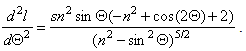
- Equations (3) and (8) to calculate the areas of decreasing and increasing the width of light transmission only differ in signs in front of the difference of offsets of the refracted beams (lc-l and l-lc). Consequently, the value of light transmission coefficient is determined by the difference between the offset at the given and the characteristic incidence angles. Figure 3 shows the dependence of this difference on the incidence angle for the characteristic angles of the filter through every 10 degrees with decreasing and increasing the width of light transmission. The differences of the offsets are shown in units relating to the glass thickness. Refractive index is n=1.5.
 | Figure 3. The dependence of difference of the offsets of refracted beams on the incidence angle at different characteristic angles of the filter |
 | (12) |
5. Features of the Calculation of a Coaxial-cylindrical Filter
- Graphic-analytical method for calculating the characteristics of light transmission is applicable not only for filters with the simplest plane-parallel form. Input and output surfaces of the filter may be non-parallel planar or curvilinear. At a complex movement of a light source and a filter relative to each other (for example, path of the sun relative to the window), the plane of incidence is changed continuously, in contrast to Figure 1. The schemes with non-parallel incident beams are possible in optical systems and lighting devices. In Figure 4 the divergent beams, incident on the filter with curved surfaces are shown. One mutual position of the light source and the filter is selected as the characteristic position. The sizes and configuration of alternating strips of the input gratings are selected in advance. Then traces of these strips on the output surface, formed by refracted beams are defined. Alternating strips of the output gratings (their boundaries shown in Figure 4 by dotted lines) are arranged symmetrically with respect to these traces under the characteristic position of the light source and the filter. To calculate the directional light transmission by equation (1) at different positions of the light source and the filter the corresponding areas are determined.Figure 5 shows the scheme of calculating filter with coaxial-cylindrical surfaces of radii R1 and R2 (filter glass thickness s=R2-R1). The beams 1 are falling on the input surface at the characteristic angle
 measured from the horizontal. In contrast to the plane-parallel filter, at alternating strips of equal width (the length of the arcs in Figure 5) on the input gratings the widths of strips on the output gratings are different. In addition, the values of the angles of incidence
 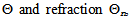 the offsets l and lengths d of paths of the refracted beams are increasing also. The filter with transmissive strips of the output gratings coinciding with traces of transmissive strips of the input gratings, has a maximum transmission at characteristic angle. The Figure 5 shows that at incidence of the beams 2 under different angle the light transmission is reduced.
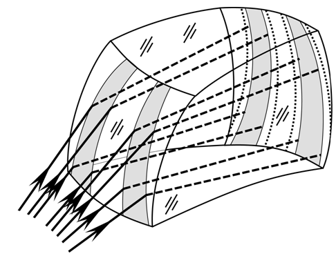 | Figure 4. The scheme of determining traces of alternating strips on the output surface of the filter |
 | Figure 5. The scheme for calculating a coaxial-cylindrical filter:  – central angle, R2 and R1 – radii of input and output cylindrical surfaces – central angle, R2 and R1 – radii of input and output cylindrical surfaces |
 | (13) |
 | (14) |
 | (15) |
 is expressed in radians, R is the radius of the circle (R2 and R1 at the input and output gratings).Equations (13)–(15) are also valid for calculating parameters of the filter with concentric spherical surfaces (in the planes of incidence).
6. Potential Applications of the Filter
- Application of the considered method presents opportunities for the creation of a novel family of filters for many different purposes. In particular, such a filter would be useful for architectural glazing to control the light transmitted into the room in a way that depends on the incidence angle without the use of additional redirecting devices. The alternating strips adapted to the trajectory of the sun relative to the specified window (for example, in the hottest season of the year) may be used on the surfaces of window glazing. Compared with sun-blinds and other devices, the filter does not require manual or automatic control, is easy to use in windows with bent and inclined surfaces, and creates the possibility of dividing the window area into zones with different characteristics of light transmission.Except the calculation of protection from the sun at known latitude of district for a given window with a known azimuth and parameters of surrounding buildings, the complex calculation for providing invisibility from the windows of opposing buildings, and also reduction of thermal losses with long-wavelength radiance from the heating devices is possible. For such bilateral regulation of light and heat transmission it is possible to apply more than two gratings with different optical and geometrical parameters.When necessary the angular selective regulation of light transmission, the use of the filter in other areas such as vehicles, production of optical systems, lighting equipment and eyeglasses is possible.
7. Conclusions
- In this paper, a novel grating optical filter for the angular selective regulation of light transmission and a graphic-analytical method for calculating its parameters are presented. The regularities of calculation for the plane-parallel and cylindrical-coaxial filters are obtained that need to be taken into account to achieve the desired angular characteristics of regulation.Preliminary selection of the geometric parameters of alternating strips of filter gratings allows to pre-adapt the regulation of light transmission at the pre-known trajectory of the light source. This approach opens up possibilities for a novel family of the filters with wide applicability in various fields, particularly in architectural glazing.