-
Paper Information
- Previous Paper
- Paper Submission
-
Journal Information
- About This Journal
- Editorial Board
- Current Issue
- Archive
- Author Guidelines
- Contact Us
International Journal of Optics and Applications
p-ISSN: 2168-5053 e-ISSN: 2168-5061
2013; 3(4): 40-52
doi:10.5923/j.optics.20130304.02
Modelling of Compound Parabolic Concentrators for Photovoltaic Applications
 Abstract
 Reference
 Full-Text PDF
 Full-text HTML
A. Antonini1, M. Stefancich2, J. Coventry3, A. Parretta4, 5
1Italian Institute of Technology, Via Morego 30, 16163 Genova (GE), Italy
2Masdar Institute of Technology, Abu Dhabi, United Arab Emirates
3Wizard Power Pty Ltd, 11 McKay Gardens, Turner ACT 2612, Australia
4Physics Department, University of Ferrara, Via Saragat 1, 44122 Ferrara (FE), Italy
5ENEA C.R. “E. Clementel”, Via Martiri di Monte Sole 4, 40129 Bologna (BO), Italy
Correspondence to: A. Antonini, Italian Institute of Technology, Via Morego 30, 16163 Genova (GE), Italy.
| Email: |  |
Copyright © 2012 Scientific & Academic Publishing. All Rights Reserved.
In this paper ways of using compound parabolic concentrators as primary optical elements for concentrated photovoltaics are evaluated. The problems related to these classical non-imaging optical elements for photovoltaics applications have been evaluated by modelling different types of linear and point focus concentrators. Particular consideration is given to the issues of manufacturability and cost. The non-uniformity of the flux resulting at the concentrator exit aperture has been considered and some solutions are proposed in order to reduce adverse effects on performance, as well as to increase the angular tolerance of the system.
Keywords: Solar Concentrators, Photovoltaic Conversion, Optical Design
Cite this paper: A. Antonini, M. Stefancich, J. Coventry, A. Parretta, Modelling of Compound Parabolic Concentrators for Photovoltaic Applications, International Journal of Optics and Applications, Vol. 3 No. 4, 2013, pp. 40-52. doi: 10.5923/j.optics.20130304.02.
Article Outline
1. Introduction
- Concentrator photovoltaics (CPV) systems[1,2] in use today can be divided, in first instance, into two main categories: Fresnel lens refractors and parabolic reflectors. Both can be either point focus (3D) or linear focus (2D) concentrators. The concept of the compound parabolic concentrator (CPC) as a primary concentrator has received some attention in the field of building integrated PV, but only for low concentration (<5x) non-tracking applications [1-3] with few exceptions[4,5]. For solar tracking applications, CPCs offer the possibility of high solar concentration ratios, in principle approaching the theoretical limits[6,7]. However, one of the largest hurdles in the use of CPCs for primary optics in PV concentrators is their unwieldy character and the necessary high material usage. This can in part be offset by reducing the length of the CPCs with the so called truncated CPCs, or T-CPCs, which use far less material with only a minor reduction in concentration ratio and optical efficiency[6,8]. Despite this improvement, the surface area of the primary optical component remains high compared to a lens or a parabolic mirror. In this paper, some new possibilities for cheap and easily manufactured CPCs will be discussed, as alternative of the more diffused concentrators based on lenses or parabolic troughs for the medium and medium-high levels of concentration positioned on trackers for large scale, field applications.CPCs offer some technical advantages: compared to a classic parabolic reflector, a CPC can be used with a less precise tracking system, due to the flat optical efficiency response, opening up the possibility of using cheaper commercial trackers not normally suitable for CPV; moreover, compared to a Fresnel lens, the optical efficiency of a CPC is higher. The best designed lenses currently available show optical efficiencies <90%[9,10], while the performances of CPCs can be limited with good approximation only by the reflectivity of the optical surface; indeed, the smoothness of the CPC’s surface helps to strongly reduce the manufacturing defects limiting more complex, structured designs. Therefore, optical efficiency can be higher than 90% with advanced reflective films or coatings, such as those discussed in this paper. Additionally, some of these materials permits to filtering unwanted portions of the solar spectrum, which is advantageous in minimizing cooling requirements for the solar cell.In common with most high concentration PV systems, the use of a flux homogenizer could be considered. As discussed in this paper, the flux profile at the outlet aperture of a CPC is highly non-uniform, and therefore the impact on cell performance for a concentrator cell can be deleterious. The design of the homogenizer suited to a CPC is discussed.
2. Background
- Descriptions of the CPC began appearing in literature in the mid-1960s[11,12]. As described by[6], the CPC was used for many different applications, ranging from high-energy physics to solar energy collection. In the field of solar energy, CPCs have mainly been used in solar thermal applications, most commonly as static linear collectors focusing light onto evacuated tubes at low concentration (~1.5x). There are applications where CPCs are used as the primary concentrator with photovoltaic cells, and other where they have been considered as secondary, non-imaging concentrator stage for some PV concentrator systems. Some projects have looked at the use of CPC troughs for combined PV-thermal (PV/T) applications[13]. In Sweden, Brogren firstly explored the use of CPCs for PV/T applications that require water for space heating[14], then further investigated[15,16]. One of the advantages that CPCs offer with respect to conventional imaging systems (parabolic mirrors and some Fresnel lenses) is their higher tolerance to misalignments with respect to the sun disk direction. Since CPCs approach the behaviour of ideal concentrators, their optical efficiency can be kept closed to unity up to the acceptance angle with a reduction factor for the entrance flux of only the cosine of the misalignment angle. As a consequence, for a given optical concentration ratio, they show the largest acceptance angle. The requirement on tracking accuracy is therefore lower, compared to other concentrators with the same concentration ratio.Most Fresnel lens systems concentrate light onto single solar cells with a point focus approach, rather than onto dense arrays of series connected cells. The significant advantage of this approach is that the problems of cell current mismatch are largely avoided (cells will still need to be series connected with other cells to build voltage, but, if the optical efficiency of each lens is the same, then cell currents should also be well matched). Single cells are able to tolerate a reasonably high degree of light non-uniformity, however, as discussed by[17,18], there can be a reduction in efficiency. In addition, when lenses for high concentration are used in conjunction with multi-junction cells, the effect of the non-uniformity can be a more serious problem because of the different light deflections for the different wavelengths converted by the cells in stack[19]. This problem is avoided for concentrators using reflective optics. Secondary flux homogenisers can be employed to give near uniform light distribution on the cells. They are frequently used for both lens systems[19,20] and parabolic dishes [21-23]. The simplest flux homogenisers are rectangular boxes with reflective sidewalls (i.e. a kaleidoscope). Solid blocks made of plastic or glass, using the principles of total internal reflection, may realize the same design. However, care must be taken to avoid melting due to strongly focused spots of concentrated light.
3. CPC Design
- The CPCs can be designed to concentrate light in either two or three dimensions. Obviously, the 2D-CPC has a lower concentration factor. According to[6], they can be designed following the Eq.s (1, 2), as a function of the concentration ratio C(ND), the required acceptance angle θi and the refractive index nout of the material at the exit aperture, for a CPC with ND dimensions:
 | (1) |
 | (2) |
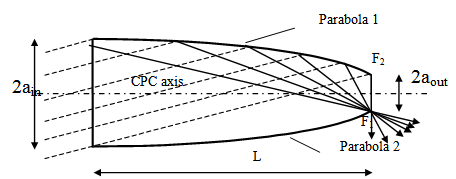 | Figure 1. Geometrical construction of a CPC; the dashed lines represent rays tilted of the acceptance angle of the structure |
4. 2D Concentrator Systems
- 2D-PV concentrator systems have been extensively studied, both theoretically and experimentally, with both reflecting mirrors[24,25] as well as with lenses[26,27]. The 2D-CPCs are not commonly used in PV applications because the length of the two parabolic reflective walls appears to be excessive for large scale purposes. For example, for a concentration factor of 30x on a 4-cm wide cell (the same size used in the EUCLIDES project[24]), the length of an ideal CPC collector results 19m long. Even an halved-CPC is too long for any practical applications. The 2D-CPC is an ideal concentrator in terms of light concentration factor for a given acceptance angle, but, for PV applications, the ideal characteristics for the optical efficiency are not strictly required. The necessity for the optical systems, in fact, is to operate at an incident angle range for the impinging radiation at which its efficiency is the highest. In general, for the CPCs, the enhancing of the concentration factor leads to an increasing of the object length; besides, the higher the concentration ratio, the lower the angular acceptance of the system. The shortening of the CPC involves a small loss of concentration and a small gain of angular tolerance, if the truncation is produced in the region of the parabola where the sloping is lower, i.e. from the entrance aperture. So, it is possible to design a truncated CPC concentrator far shorter than the ideal one for a given concentration factor, reducing the length of an ideal CPC of higher concentration ratio and of lower angular acceptance, achieving a structure with higher angular acceptance respect to the ideal one and considerably shorter.Eq. (3) defines a T-CPC, with the main parameters given in Fig 2, as exhaustively described in[2].
 | (3) |
 | Figure 2. Schematic representation of a truncated CPC; the complete CPC of length L is shortened up to the length equal LT |
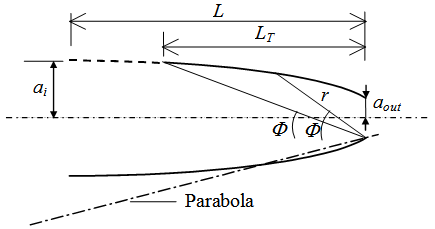
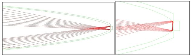 | Figure 3a. Raytrace on a 2D, truncated CPC for a beam of incident rays tilted of 0.6° respect to the CPC axis; the structure is not filled with dielectric material. The incoming beam is the bottom one |
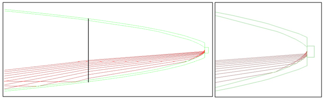 | Figure 3b. The same raytrace on a CPC partially filled at the exit for 2.5 cm with dielectric with n = 1.49 |
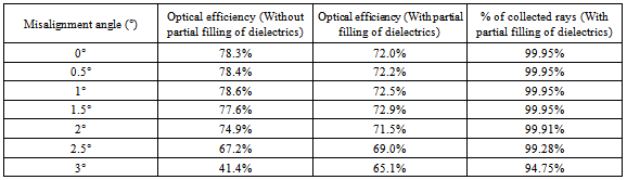
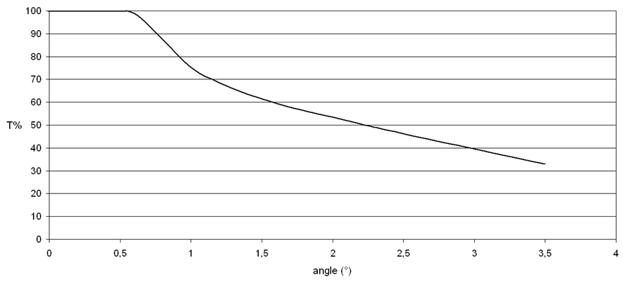 | Figure 4. Transmission-angle characteristic of the partially filled 2D T-CPC |
 | (4) |
 | (5) |
 represent the angles of incidence for the incoming radiation, in spherical coordinates, while
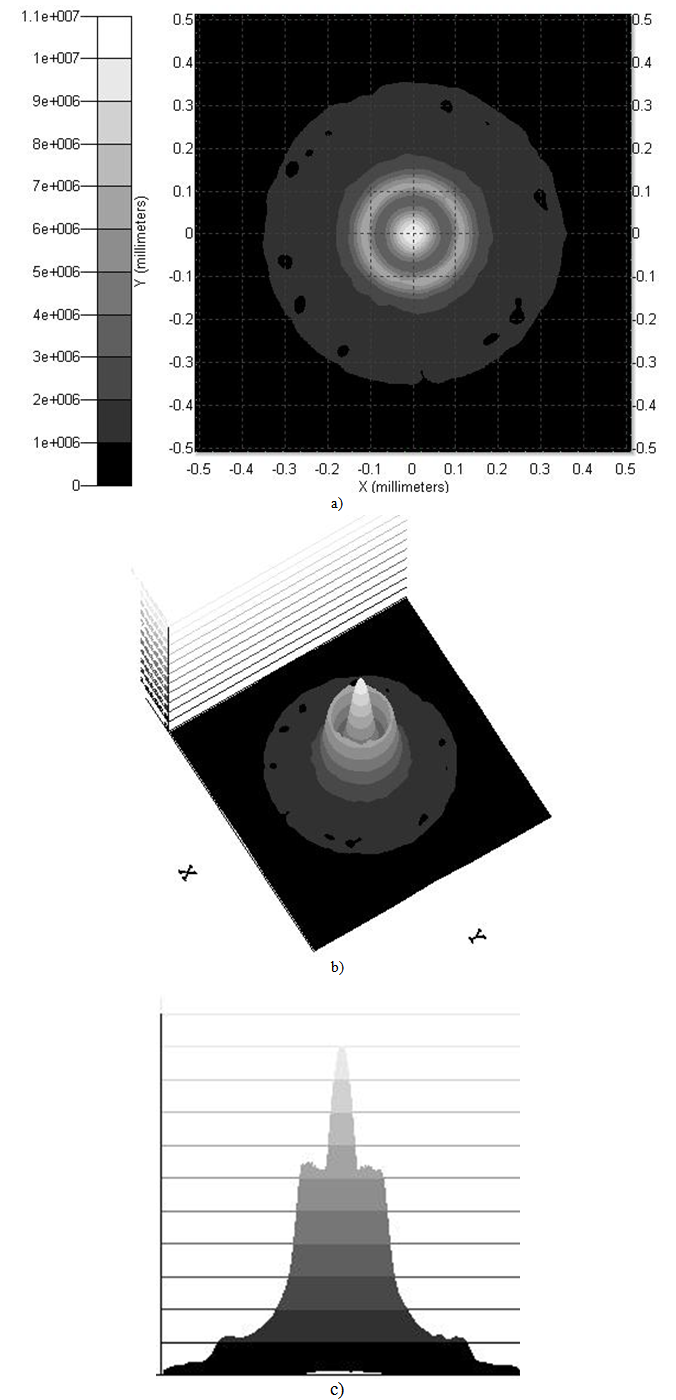
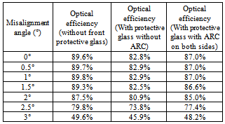
  are the angles indicating the scattering direction. Lsis the scattered radiance, while Ei is the incident irradiance. This optical property has been introduced to consider the slight effect of the light diffusion at the reflector surfaces. Because of the Fresnel reflection at the interfaces of materials of different refraction indexes, portion of the incident light flux is back reflected at the interfaces of the protective glass and of the encapsulant; this factor of losses, common with every concentrator system using lenses, can be strongly reduced depositing an antireflection layer on the surfaces, which are, in this case, all planar.The very thin and long illuminated area of this proposed design has the additional advantage of a very high perimeter/surface ratio for the PV device, which permits to cool down the cells using passively, maximizing the thermal spreading effect at the receiver level.The necessity of flux uniformity on a single cell significantly depends on the particular kind of cell employed; indeed, the cell size, the contact pattern and coverage, the doping levels and the external circuit configurations play all an important role. In the supposed case of Sliver cell used for the 2D-CPCs system, there’s a fairly high tolerance for non-uniformity on the device, because the emitter contact is placed on the side of the device, and its small dimension is in the direction perpendicular to the incoming radiation, which is of the order of the electrons diffusion length, for Si with lifetime higher than 200µs. For symmetrical reasons, the uniformity along the long dimension of the device is ensured, so uniform light could be expected along the string of series connected cells. A flux profile along the short side of the cell is graphed in Fig. 5 for different misalignments, with an encapsulating material with the optical properties of PMMA filling the CPC up to 25mm from the cell plane.
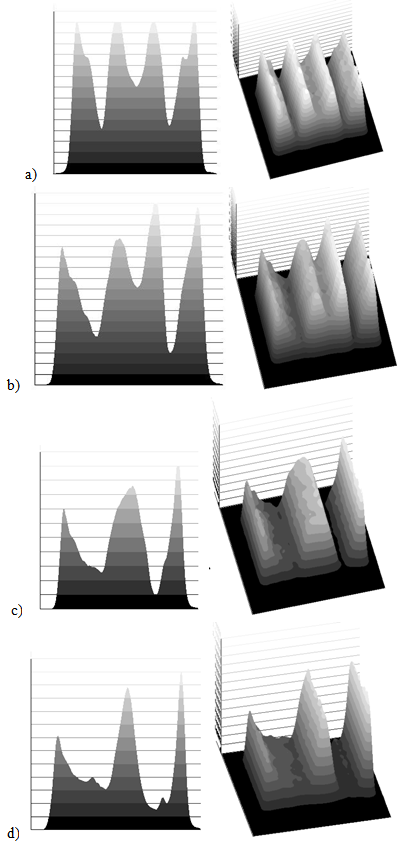 | Figure 5. Lateral (left) and 3D view (right) of the energy flux distribution on a sector of the receiver for the 2D, 30× CPC considered, from optical simulations, for four different angle of misalignment (including the solar divergence effect): a) 0°; b) 0.2°; c) 0.4°; d) 0.6° |
5. 3D Concentrator Systems
- In the case of 3D-CPCs it’s possible to consider a system assembly similar to that used with a 3D-lenses concentrator. An illustration of an array of these 3D-CPCs objects is shown in Fig. 6.
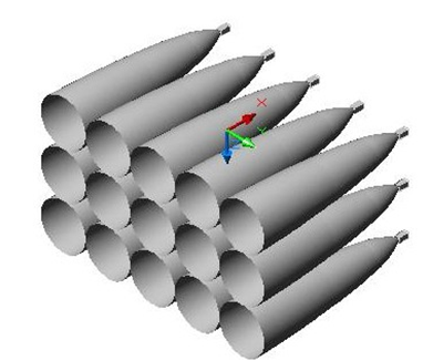 | Figure 6. 3D view of an array of 3D-CPCs, each one with a terminal kaleidoscope for the light flux homogenisation |
 | Figure 7. Top (a), 3D (b) and lateral view (c) of the energy light flux distribution at the exit aperture of the 115× 3D CPC; the intensity scale is in arbitrary units |
|
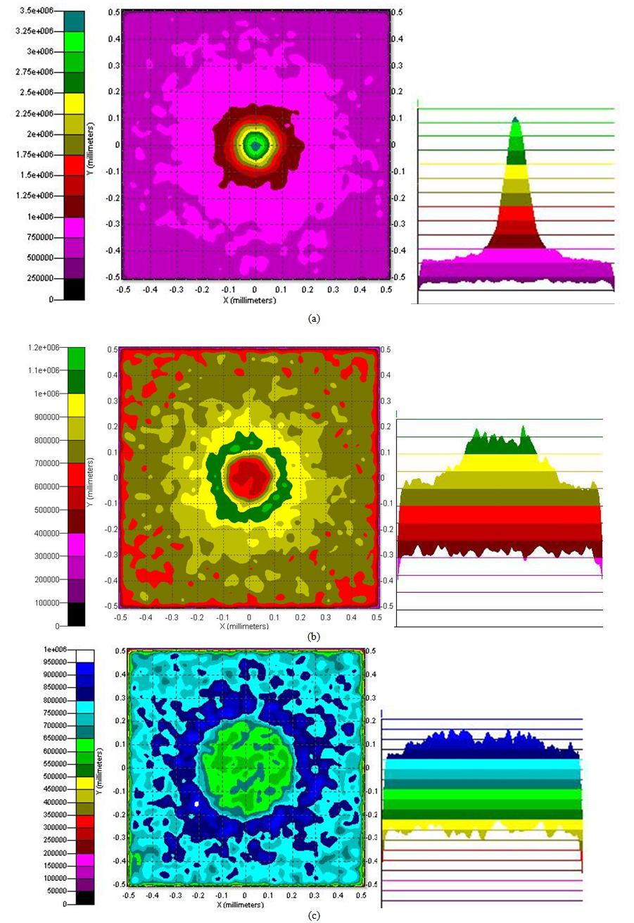 | Figure 8. Flux distribution on the target (map on the left and lateral profile on the right), without dielectric, for different mixer lengths: (a) 2 cm, (b) 2.5 cm, (c) 3 cm |
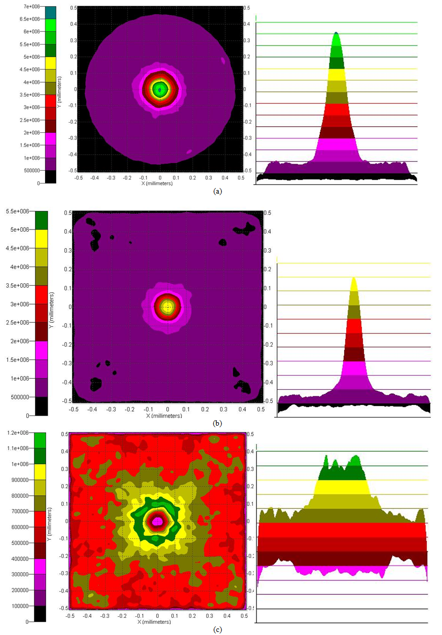 | Figure 9. Flux distribution on the target (map and lateral profile) for different mixer lengths: (a) 2 cm, (b) 2.5 cm, (c) 3 cm, with dielectric filling the kaleidoscope structures and part of the exit of the CPC |
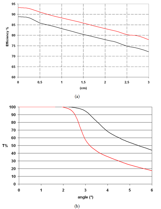 | Figure 10. Optical efficiency vs. kaleidoscope length (a) and transmission angle curve (b) for the 3D-CPC with and without partially filling with dielectric (black and red line respectively) |
|
6. Materials
- Because of the particular geometries required for the surface profiles, the fabrication of the structure can be done by plastic moulding. Computer controlled machining tools can work surface profiles with the CPCs curvature, with a precision level of 0.01mm; the smooth curvature required for these objects takes out the fabrication problems, own of Fresnel lenses, of achieving very sharp corners. The reflectance of the surface can be ensured by metallization with Al, Ag or applying reflective films; in any case the reflective coating must be properly covered with polymeric layers acting as protective barriers against moisture.The large interest in high reflective, low cost materials for solar concentrator, both for PV as well as for thermal application has lead to a large body of literature on this issue. Reflective materials have very good optical properties, even for large scale and low cost production[34-36]. For the here modelled structures, both reflective adhesive films as well as evaporated metal coatings directly deposited on the concentrator surfaces can be evaluated. For the particular geometries of the CPCs, the specular reflectance of the surfaces has to be evaluated at high angles of incidence for the light beam. Metallic reflectors have high insensitivity to the light impinging angle, as shown in the measured results in Fig. 11 for a glass coated with silver, tested for two different light wavelengths. The peak reflectance at higher angles in Fig. 11b is due to the Fresnel reflection. Nevertheless, multi-layer polymeric films also demonstrate very high reflectance for all the incidence angles[38].
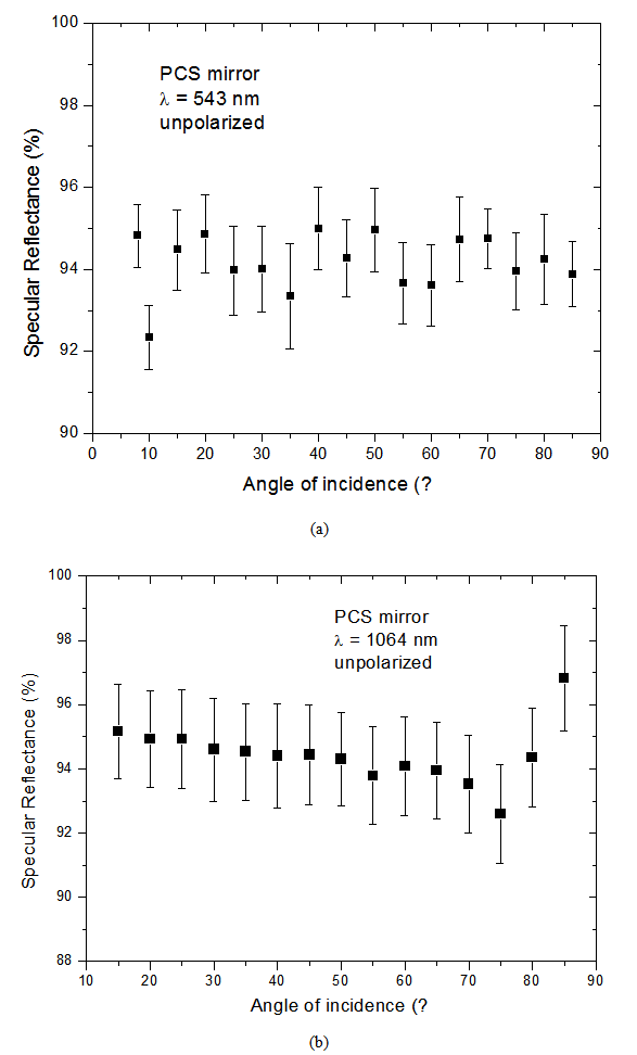 | Figure 11. Experimental results of specular reflectance for a silvered mirror at different angles of light incidence, for two different wavelengths, 543 nm (a) and 1063 nm (b). The measurements have been carried out at the glassed side of the mirror |
7. Conclusions
- The use of some CPC designs as primary concentrators for CPV has been described. Both 2D and 3D CPC structures have been evaluated and some particular solutions have been selected for possible photovoltaic applications. Historically, the large reflective area required for CPCs has limited their use to being secondary collectors or concentrators for low level of concentration, but, considering the very low price of currently available, high efficiency film reflectors, or the possibility of industrially coating small size structures with high reflective metals, this family of optical objects can be considered as a competitive choice for CPV applications.The industrial development of very narrow linear concentrator cells has opened up the possibility of linear micro-concentrators. The particular shape of this kind of cells is suitable for linear concentrators, where each cell represents an element of a string of cells along a trough. The small width of the cells allows the use of CPCs, a class of concentrators not normally employed for large scale photovoltaic applications because of their intrinsically large dimensions, despite the fact that they have almost ideal non-imaging optical properties. By moving toward very small devices, it is possible to achieve concentrators of reasonable size with the inherent advantages of this class of optical object, i.e. their good tolerance at misalignment errors and the possibility of employing low cost but with very high reflective materials leading to high optical efficiency. Moreover, the very thin width of the cell permits efficient cooling at medium level concentration ranges, increasing the overall system efficiency.3D-CPCs can be employed in the range of 100×, permitting very high optical efficiency (closed to 90%) for real devices produced with available industrial technology. The detrimental effect of the high non-uniformity in the light distribution at the target can be corrected with low optical losses, using a kaleidoscopic transparent dielectric material, acting for total internal reflections, working as light guide, and for mixing the radiation concentrated by the truncated CPC.
References
| [1] | Mallick, T.K., Eames, P.C., Norton B., 2006, Non-concentrating and asymmetric compound parabolic concentrating building facade integrated photovoltaics: An experimental comparison, Solar Energy, 80(7), 834-49. |
| [2] | NabinSarmah, Bryce S. Richards, Tapas K. Mallick, 2011, Evaluation and optimization of the optical performance of low-concentrating dielectric compound parabolic concentrator using ray-tracing methods, Applied Optics, 50(19), 3303-3310. |
| [3] | Yuehong Su, Saffa B. Riffat, Gang Pei, 2012, Comparative study on annual solar energy collection of a novel lens-walled compound parabolic concentrator (lens-walled CPC), Sus-tainable Cities and Society, Vol. 4, 35-40. |
| [4] | Antonimi, A., Butturi, M.A., Di Benedetto, P., Uderzo, D., Zurru, P., Milan, E., Stefancich, M., Armani, M., Parretta, A., Baggio, N., 2009, Rondine® PV concentrators: Field results and developments, Progress in Photovoltaics: Res. Appl., 17(7), 451-459. |
| [5] | Hatwaambo, S., Hakansson, H., Nilsson, J., Karlsson, B., 2008, Angular characterization of low concentrating PV-CPC using low cost reflectors, Solar Energy Materials and Solar Cells 92(11), 1347-1351. |
| [6] | W.T. Welford and R. Winston, High Collection Nonimaging Optics, Academic Press, San Diego, 1989. |
| [7] | Smestad, G., Ries, H., Winston, R., Yablonovitch, E., 1990, The thermodynamic limits of light concentrators, Sol. Energy Mater., 21(2–3), 99-111. |
| [8] | Parretta, A., Martinelli, G., Stefancich, M., Vincenzi, D., Winston, R., 2003, Modelling of CPC-based photovoltaic concentrator, Proc. of SPIE, Vol. 4829, pp. 1045-1047. |
| [9] | Araki, K., Emery, K., Siefer, G., Bett, A.W., Sakakibara, T., Kemmoku, Y., Ekins-Daukes, N.J., Lee, H.S., Yamaguchi, M., 2005, Comparison of efficiency measurements for HCPV module with 3J cells in 3 sites, Proc. 31st IEEE PVSC, pp. 239-242. |
| [10] | Jing, L., Liu, H., Lu, Z., Zhao, H., 2010, Design of compound Fresnel-R lenses for new high-efficient concentrator, Proc. of SPIE, Vol. 7785, pp. 77850K-77850K-10. |
| [11] | Hinterberger, H., Winston, R., 1966, Efficient Light Coupler for Threshold Čerenkov Counters, Rev. Sci. Instrum., 37(8), 1094-1095. |
| [12] | Baranov, V.K., Melnikov, G.K., 1966, Study of the illumi-nation characteristics of hollow focons, Sov. J. Opt. Technol., Vol. 33, pp. 408-411. |
| [13] | M. Brunotte, A. Goetzberger, and U. Blieske, Two-stage concentrator permitting concentration factors up to 300x with one-axis tracking, Solar Energy, 56(3), 285-300. |
| [14] | Brogren, M., Nostell, P., Karlsson, B., 2000, Optical Efficiency of a PV-Thermal Hybrid CPC Module, Proc. Eurosun 2000 - ISES Europe Solar Conference, Copenhagen, Denmark. |
| [15] | Mohd. YusofHj. Othman, BaharudinYatima, Kamaruzzaman Sopianb, Mohd. Nazari Abu Bakara, 2005, Performance analysis of a double-pass photovoltaic/thermal (PV/T) solar collector with CPC and fins, Renewable Energy, 30(13), 2005-2017. |
| [16] | David A.G. Redpath, Harjit Singh, Christopher Tierney, Philip Dalzell, 2012, An Experimental Comparison of two Solar Photovoltaic - Thermal (PVT) Energy Conversion Systems for Production of Heat and Power, Energy and Power, 2(4), 46-50 |
| [17] | Franklin, E., Coventry, J.S., 2002, Effects of Highly Non-uniform Illumination Distribution on Electrical Perfor-mance of Solar Cells, Proc. ANZSES Solar Conference, Newcastle, Australia. |
| [18] | Antonini, A., Stefancich, M., Vincenzi, D., Malagù, C., Bizzi, F., Ronzoni, A., Martinelli, G., 2003, Contact grid optimization methodology for front contact concentration solar cells, Solar Energy Materials and Solar Cells. 80(2), 155-166. |
| [19] | Leutz, R., Suzuki, A., Akisawa, A., Kashiwagi, T., 2001, Flux uniformity and spectral reproduction in solar concentrators using secondary optics, Proc. ISES Solar World Congress, Adelaide, Australia. |
| [20] | Leutz, R., Suzuki, A., Akisawa, A., Kashiwagi, T., 2001, Nonideal concentration of nonimaging linear Fresnel lenses, Proc. Nonimaging Optics: Maximum Efficiency Light Transfer VI, San Diego, CA. The International Society for Optical Engineering, 2001, pp.100-109. |
| [21] | Ries, H., Gordon, J.M., Lasken, M., 1997, High-flux photo-voltaic solar concentrators with kaleidoscope-based optical designs, Solar Energy 60(1), 11-16. |
| [22] | Chen, M.M., Berkowitz-Mattuck, J.B., Glaser, P.E., 1963, The Use of a Kaleidoscope to Obtain Uniform Flux Over a Large Area in a Solar or Arc Imaging Furnace, Applied Optics 2(3), 265-272. |
| [23] | Kreske, K., 2002, Optical design of a solar flux homogenizer for concentrator photovoltaics, Applied Optics, 41(10), 2053-2058. |
| [24] | Luque, A., Sala, G., Arboiro, J.C., Bruton, T., Cunningham, D., Mason, N., 1997, Some Results of the EUCLIDES Photovoltaic Concentrator Prototype, Prog. Photovoltaics: Res. Appl., Vol. 5, pp. 195-212. |
| [25] | Coventry, J.S., 2005, Performance of a concentrating photo-voltaic/thermal solar collector, Solar Energy, 78(2), 211-222. |
| [26] | Leutz, R., Suzuki, A., Akisawa, A., Kashiwagi, T., 2000, Shaped nonimaging Fresnel lenses, J. Opt. A: Pure Appl. Opt. 2(2), 112-116. |
| [27] | Leutz, R., Suzuki, A., Akisawa, A., Kashiwagi, T., 1999, Design of a nonimaging Fresnel lens for solar concentrators, Solar Energy, 65(6), 379-387. |
| [28] | Franklin, E., Blakers, A., 2004, SLIVER® Cells for Con-centrator Systems, Proc. 19th EPSEC, Paris, France. |
| [29] | Blakers, A.W., Deenapanray, P.N.K., Everett, V., Franklin, E., Jellett, W., Weber, K.J., 2005, Recent Developments in SLIVER Cell Technology, Proc. 20th EPSEC, Barcelona, Spain. |
| [30] | V. Díaz, J. Alonso, J.L. Alvarez, C. Mateos, The Path for Industrial Scale Production of Very High Concentration PV Systems, Proc. 20th EPSEC, June 6-10, 2005, Barcelona, Spain. |
| [31] | Anton, I., Sala, G., 2005, Losses caused by dispersion of optical parameters and misalignments in PV concentrators, Prog. In Photovoltaics: Res. Appl. 13(4), 341-352. |
| [32] | R. Winston, R, C. Gee, Nonimaging light concentrator with uniform irradiance, US Patent 6,541,694 B2, April 1, 2003. |
| [33] | Leutz, R., Ries, H., 2003, Squaring the Circle - The Use of Microstructures for Converting and Homogenizing Beam Patterns, Proc. SPIE Vol. 5186, Design of EfficientIllumi-nation Systems, 106, Nov. 10, 2003; doi:10.1117/12.506792. |
| [34] | Nostell, P., Roos, A., Karlsson, B., 1998, Ageing of solar booster reflector materials, Sol. Energy Mater. Sol. Cells, 54(1-4), 235. |
| [35] | B.M. Clive, “Very low cost PV concentrators”, ETSU S/P2/00349REP, DTI/Pub URN 01/1120. |
| [36] | J. Harrison, “Investigation of Reflectivity Materials for the Solar Cooker”, Florida Solar Energy Center, 24-12-2001. |