-
Paper Information
- Paper Submission
-
Journal Information
- About This Journal
- Editorial Board
- Current Issue
- Archive
- Author Guidelines
- Contact Us
International Journal of Optics and Applications
p-ISSN: 2168-5053 e-ISSN: 2168-5061
2013; 3(3): 15-18
doi:10.5923/j.optics.20130303.01
Point Diffraction-Reference Surface Method for Testing Optical Flats
Ogaro Elijah Nyakang’o1, Geoffrey Kihara Rurimo2, Patrick M. Karimi1
1Department of Physics Kenyatta University, Nairobi, Kenya
2Department of physics Jomo Kenyatta University of Agriculture and Technology, Nairobi, Kenya
Correspondence to: Geoffrey Kihara Rurimo, Department of physics Jomo Kenyatta University of Agriculture and Technology, Nairobi, Kenya.
| Email: |  |
Copyright © 2012 Scientific & Academic Publishing. All Rights Reserved.
We present a point diffraction-reference surface interferometer that can either use a pinhole or a single-mode fiber as a point diffraction source. The interferometer configuration employs a two-step flat surface measurement procedure to provide relative measurement of optical flats. In the interferometer configuration, the first reference flat is maintained in the same position for both first and second measurement while the test flat is replaced by a second reference flat in the second measurement. This mode of measurement allows subtraction of errors introduced by the first reference flat, the beamsplitter and the auxiliary optics as they are not moved from their positions during measurements.
Keywords: Point Diffraction, Optical Flats Measurement, Interferometers
Cite this paper: Ogaro Elijah Nyakang’o, Geoffrey Kihara Rurimo, Patrick M. Karimi, Point Diffraction-Reference Surface Method for Testing Optical Flats, International Journal of Optics and Applications, Vol. 3 No. 3, 2013, pp. 15-18. doi: 10.5923/j.optics.20130303.01.
Article Outline
1. Introduction
- The accuracy of planeness metrology has made significant progress in the last decades due to novel interferomentry measurement methods. Particularly noticeable measurement method is one which use a liquid surface as a natural reference flat in the Fizeau interferometry configuration[1]. However, problems with vibrations of the liquid surface, thermal gradients, surface particles and the meniscus due to the walls of the container are all critical to the uncertainty of such measurement. A precise measurement method described in[2, 3] to replace the liquid surface test technique is the “three-flat test” method which has been in use for decades now. The measurement and analysis techniques of the “three-flat test” method has been extended further to determine the flatness deviations along several sections of each flat surface[4-7]. Other measurement and analysis techniques on the extension of the “three-flat test” method are extensively discussed in several publications[8-11].But even with the advancement of the analysis methods in the “three-flat test” method, little attention is paid to errors contributed by the beamsplitter and the auxiliary optics. The term auxiliary optics is used here to refer to the other optics outside the interferometer such as collimators and imaging lenses. In this paper, we present a point diffraction-reference surface interferometer configuration that is using a two-step flat surface measurement procedure to eliminate the errors.
2. The Point Diffraction-Reference Surface Interferometer
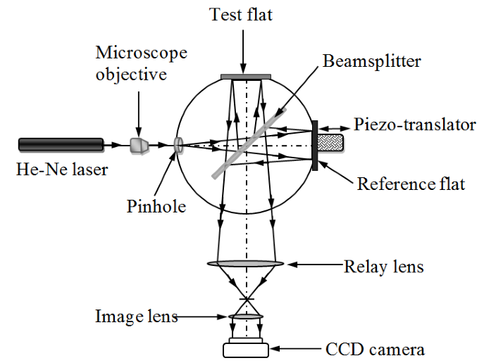
- In the point diffraction-reference surface interferometer configuration presented here, a He-Ne laser source is used to illuminate a pinhole which acts as a point diffraction source. The diffracted spherical wavefront from the pinhole is split by the beamsplitter to form the reference and test spherical wavefronts. The point diffraction wavefront reflected by the test flat is an aberrated spherical wavefront carrying the surface information of the test flat. If this aberrated spherical wavefront is allowed to interfere with the spherical reference wavefront reflecting from the reference flat, we can measure the wavefront aberrations of the test flat. However, the beamsplitter and the auxiliary optics in the interferometer also introduce errors into the measurement. The measurement errors due to the beamsplitter and the auxiliary optics can be eliminated using a two-step interferometry measurement procedure.
2.1. First-Step Measurement
- Figure 1 shows the point diffraction-reference surface interferometer configuration which depicts the first-step surface figure measurement of the test flat. The beams diffracting from the pinhole aperture have perfect spherical wavefronts over a finite range defined by the diameter of the pinhole aperture relative to the wavelength of the light source used. The diffracted spherical wavefronts is split by the beamsplitter into measurement and reference wavefronts. The measurement wavefront illuminate the test flat normally and reflects back to the beamsplitter. The reference wavefront also illuminates the reference flat normally and reflects back to the beamsplitter where it recombines and interferes with the measurement wavefront. The resulting interferogram recorded on a CCD camera, includes phase errors due to test flat, reference flat, beamsplitter and the auxiliary optics. The combined wavefront phase errors are analysed using standard phase extraction algorithms[14].
 | Figure 1. Phase errors measurement due to test flat, reference flat and auxiliary optics |
2.2. Second-Step Measurement
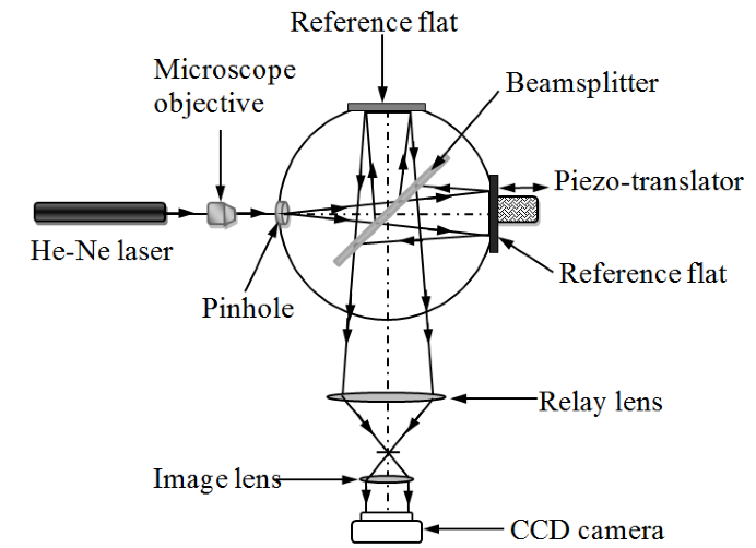
- In the second-step measurement, the test flat is then removed and replaced with a reference flat that is identical with the first reference flat as in figure 2. The diffracted spherical wavefronts is again split by the beamsplitter into two reference wavefronts. The two reference wavefront illuminates the reference flats normally and reflects back to the beamsplitter where they recombines and interferes. The resulting interferogram recorded on a CCD camera, includes phase errors due to reference flats, beamsplitter and the auxiliary optics. The combined wavefront phase errors are again analysed using standard phase extraction algorithms.
 | Figure 2. Phase errors measurement due to reference flats and auxiliary optics |
 difference between the reference flat and the test flat is obtained. The relative surface figure
  of the test flat is related to the phase error
  by,
by, | (1) |
 to
to  rms accuracy is sufficient, the surface figure error of the standard reference flat must be less than
  rms. It is also important to simplify the interferometer by eliminating parts that can compromise on accuracy of measurements. The principle axis of both the measurement and reference beams should be normally to the test flat and the reference flat respectively. The aspect of the angle of incidence at the test flat and reference flat is particularly important since the point diffraction source generate nearly ideal spherical wavefronts. Due to the diverging nature of the point diffraction wavefront, if the measurent beam is incidence on the test flat at oblique angles, the reflected beam will reveal an elliptical outline. Simiraly, if the reference beam is incidence on the reference flat at oblique angles, the reflected beam also shows an elliptical outline which is critical to the measurement accuracy[12]. It is therefore absolutely necessary to have an incident angle as close as possible to normal incidence so as to reduce the elliptical effect on measurement accuracy.The point diffraction described in this paper is based on a pinhole which provides the diffracted wavefronts. However, with the advancement of fiber fabrication technology, single-mode fibers can be used as a point diffraction source that provides high quality diffraction wavefronts. For instance the beams diffracting from the single-mode fiber of core diameter 3.5 µm and numerical aperture of 0.13 have perfect spherical wavefronts with deviation from sphericity demonstrated to be
  [13].
[13].3. Experimental Results
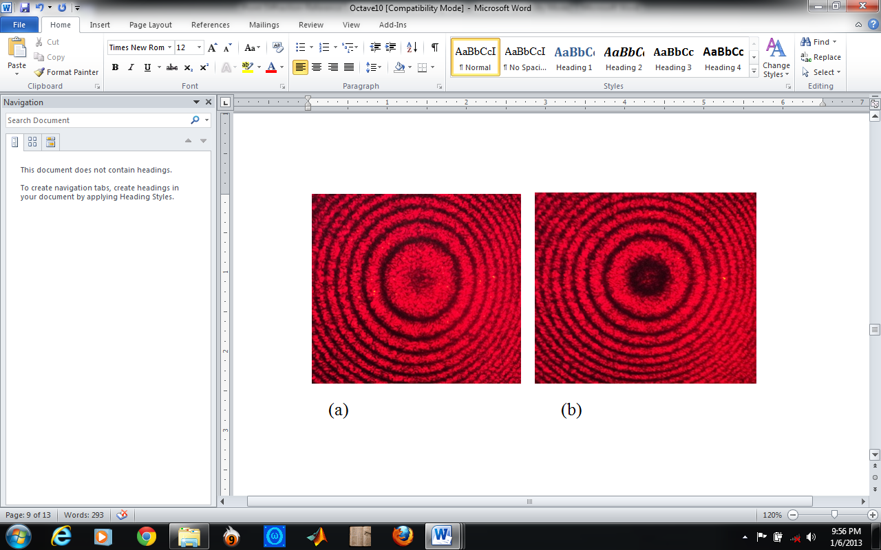
- To demonstrate the point diffraction-reference surface interferometer configurations, an experimental set up of the interferometer is as shown in figures 1 and 2. The diameter of the pinhole used is 10 µm and the microscope objective is 10x with a numeral aperture of 0.25. A beam of HeNe laser (λ= 632.8 nm) is used as the light source and figure 3 shows a typical fringe patterns obtained in the experiment.
 | Figure 3. Fringe patterns recorded for normal incidence of the point diffraction beam on the test and reference flats: (a) First-step measurement (b) Second-step measurement |
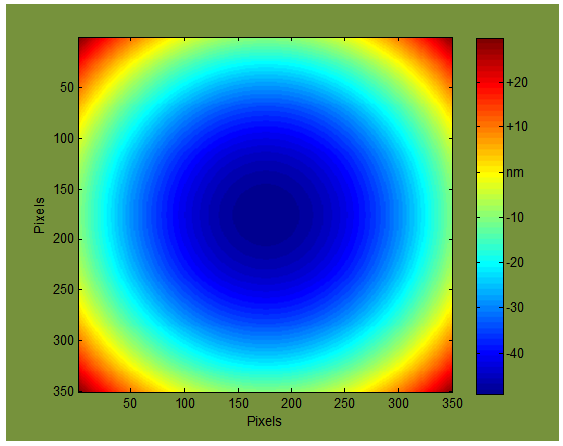
 | Figure 4. Measured profile of the flat surface, with piston and tilt removed |
4. Conclusions
- By simplifying the interferometer and using a two-step flat surface measurement procedure, the measurement errors due to the beamsplitter and the auxiliary optics are easily eliminated so as to provide relative measurement of test flats. Using this procedure, the surface quality of an optical flat can easily be verified during and after a fabrication process because the beamsplitter and the auxiliary optics are all kept in exactly the same positions throughout the two-step procedure.
ACKNOWLEDGEMENTS
- The work presented here is supported by the optical facility at Jomo Kenyatta University of Agriculture and Technology.
 Abstract
 Reference
 Full-Text PDF
 Full-text HTML