-
Paper Information
- Previous Paper
- Paper Submission
-
Journal Information
- About This Journal
- Editorial Board
- Current Issue
- Archive
- Author Guidelines
- Contact Us
International Journal of Optics and Applications
p-ISSN: 2168-5053 e-ISSN: 2168-5061
2012; 2(5): 76-79
doi: 10.5923/j.optics.20120205.04
A Possible Use of Fiber-Optic Ring Resonator as a Nano-Scale Optical Sensor for Detection of Physical Quantities
Melika E. Seraji 1, Faramarz E. Seraji 2, H. Golnabi 1, 3
1Department of Physics, Science and Research Branch, Islamic Azad Univ., Tehran, Iran
2Optical Communication Group, Iran Telecom Research Center, Tehran, Iran
3Institute of Water and Energy, Sharif University of Technology, Tehran Iran
Correspondence to: Faramarz E. Seraji , Optical Communication Group, Iran Telecom Research Center, Tehran, Iran.
| Email: |  |
Copyright © 2012 Scientific & Academic Publishing. All Rights Reserved.
This paper presents a proposed fiber-optic ring resonator with a resonance loop made of a conventional single-mode optical fiber as a nano-scale sensor for measurement of physical quantities, such as pressure and temperature. The operational theory of the resonator as an optical sensor is presented, where the effects of characteristic parameters of the resonator on the sensor response is investigated. It is shown that the behavior of sensor response with respect to some particular physical quantities is linear and is capable of detecting measurand variations of the order of 100 nanometers. The proposed sensor is suitable for design of hydrophones used in submarine communications.
Keywords: Nano-scale, Optical Sensors, Finer-optic Ring Resonator
Cite this paper: Melika E. Seraji , Faramarz E. Seraji , H. Golnabi , "A Possible Use of Fiber-Optic Ring Resonator as a Nano-Scale Optical Sensor for Detection of Physical Quantities", International Journal of Optics and Applications, Vol. 2 No. 5, 2012, pp. 76-79. doi: 10.5923/j.optics.20120205.04.
Article Outline
1. Introduction
- In the last two decades, fiber-optic ring resonators (FORRs) with fiber and waveguide structures have been used in several applications such as biosensors[1], optical switching[2], add/drop multiplexers[3], laser resonators[4], dispersion compensators[5], optical bistability[6], optical filters[7]. Recently, performance analyses of FORR under steady and dynamic states are reported, where the resonator responses in terms of characteristic parameters, are investigated[8, 9]. More recently, the use of FORR for tunable optical filters is analysed, where the resonance loop of the FORR was made of photonic crystal fibers[10]. A nano-opto-mechanical pressure sensor based on ring resonator is designed, fabricated and characterized for pressures ranging from 0 kPa to 60 kPa. The sensitivity and resolution of the pressure sensor is 1.47 pm/kPa and 1.36 kPa, respectively[11]. A novel refractometric sensor in the form of an embedded optical nanowire loop resonator is investigated experimentally, where a sensitivity as high as 700 nm/RIU and a refractive index resolution as low as 10-7 is achieved[12]. A digital optical sensor based on two cascaded ring resonators with different free spectral ranges to measure refractive index is proposed, which has shown a high sensitivity of the order of 105 nm/RIU[13].Yet in another report, a method is proposed theoretically to simultaneously measure refractive-index (RI) and temperature changes using optical ring resonators. The analysis has shown that the RI and temperature detection limits can be achieved on the order of 10-7 RI unit and 10-3 K at a wavelength of 780 nm[14]. Unlike the other methods[11-13], in the present paper, by considering the steady state response of the FORR[9], an analysis of possible use of an FORR as a nano-scale sensor for measurement of physical quantities such as pressure and temperature is presented. In the present analysis, it is shown that if the resonance loop is exposed to a physical quantity of mechanical nature, the output characteristics of the FORR will change linearly in a specified range of wavelengths in response to nano-scale variations of sensing length.
2. Structure of FORR Based Sensor
- A basic structure of an FORR is made of a 2×2 optical directional coupler with a resonance loop constructed by connecting an input port to one of the output port. In Fig. 1, the proposed FORR to measure a physical quantity is shown, where its resonance loop of length
 is exposed to a physical quantity, such as acoustic waves. The characteristic parameters of the FORR are loop transmission coefficient
  , coupler coupling coefficient
  , coupler insertion loss
  , and loop delay time
  .For our analysis of the FORR response as an optical sensor, without of loss of generality, the attenuation of the loop is assumed to be only due to macrobending, while other attenuation mechanisms such as intrinsic and joint losses are neglected. The loop transmission coefficient is obtained by
  , where
  is the attenuation coefficient due to macrobening loss in terms of dB/m.
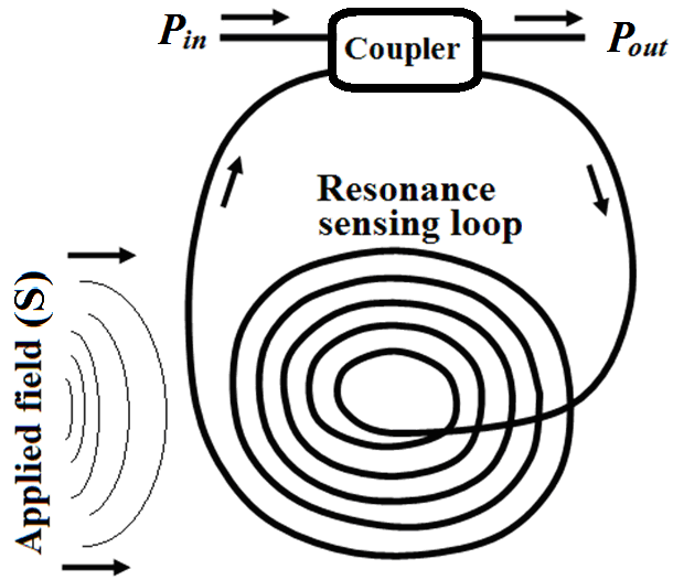 | Figure 1. The proposed nano-scale sensor based on FORR |
 is the average length of the loop and
  is the refractive index of the fiber core, the phase change
  in the optical path length of
  due to an applied physical quantity
  will be as
  [11], which shows that the physical quantity causes independent changes of the loop length and the refractive index of the core. If we use a birefringent fiber for the resonance loop, the polarization phase angle obtained in propagating mode due to two perpendicular polarization modes
  is given as
  [11]. On the other hand, the average phase of propagating mode with angular frequency of
  in the loop with delay time of
  will be
  . Therefore, from polarization phase angle
  the loop delay time is obtained as
  , where
  is the speed of light in a vacuum. If
  is the signal of angular frequency
  from a laser diode (LD) modulated by
  , is applied to the input port of the sensor, the response after
  circulations of the propagating mode in the loop, can be expressed as[10]:
 | (1) |

 and
and  are constants for a given FORR,
  is the modulation coefficient of the LD signal,
  is the optical frequency deviation (Hz/mA),
  is the modulation frequency,
  is the peak of modulating current of LD,
  is the amplitude modulation coefficient, and
  is the angle between optical frequency deviation and amplitude modulation current of the LD.
3. Response of the Sensor
- The steady state response of the FORR in terms of phase of circulating field through the resonance loop in the wavelength range of 1.4325 to 1.4410
 from Eq. (4) is illustrated in Fig. 2, using different values of loop length
  and the following specific parameters:
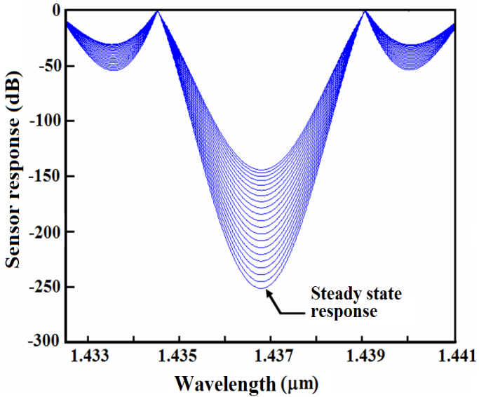 | Figure 2. Sensor responses under steady state and applied fields as a function wavelength |
 incurs decreasing variations due to different applied measurand quantities.In Figure 3, the slope of the curve
  can be a characteristic response of a given sensor based on a particular FORR. This curve may be approximated by a linear differential equation of the form expressed as:
 | (2) |
 is a constant of integration, in terms of dB.The linear nature of Eq. (2) with a sharp slope can provide a sensitive measurement of a measurand physical quantity applied on the resonant sensing loop of the resonator. By a minute investigation of the response curves in Figure 2 reveals that the sensor response is also dependent on the slope of the individual curve for different loop length variations. In the linear regime of the response curves, a measurand physical quantity is applied and the corresponding slope angles are calculated.
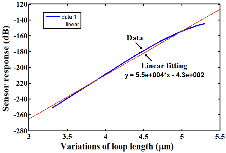 | Figure 3. Variation of sensor response in terms of loop length variation at 1.4367  |
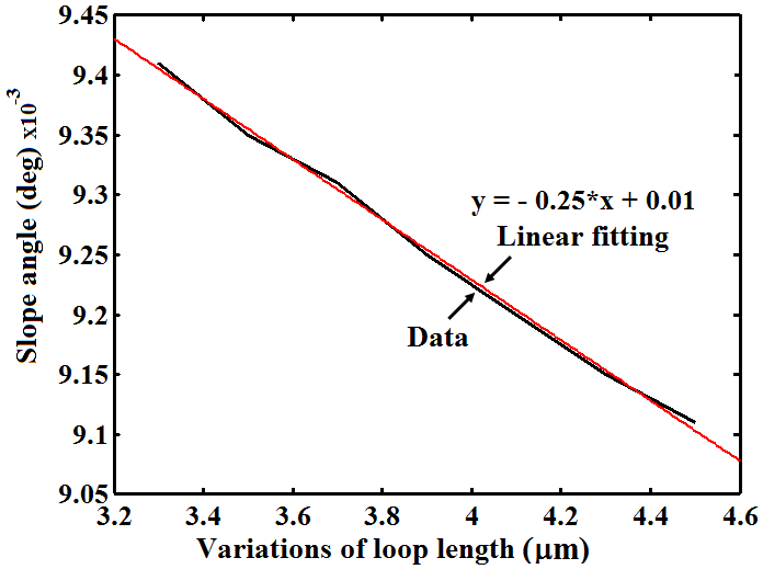 | Figure 4. Variations of slope angle versus loop length variations  |
 versus loop length
  are illustrated for a step of 200 nm. As shown, the range of loop length variations from 3.3
  to 4.5
  has reduced the slope angle from 9.41×10⁻³ to 9.11×10⁻³ deg. The slope of the curves
  in this case can also be approximated by a linear differential equation to represent the response in Figure 4 as follows:
 | (3) |
 is a constant of integration equal to 0.01 in terms of degree. In this case, the response curve has a mild slope angle as compared with the case in Eq. (2). indicating a lesser sensitivity to measurand quantity.
4. Effects of FORR Parameters on Sensor Responses
- The parameters of the FORR and laser source can also influence on the sensor response at some particular conditions[8, 9]. In our analysis, we focus on effects of the FORR parameters such as


 , and for the sake of analytical simplicity, we ignore that of laser source. The effects of other parameters are under investigation whose results will be reported elsewhere. Using Eq. (1), the effects of parameters

 and
and  on the sensor response is illustrated in Figure 5. It is indicated that the effects of
  and
and  , lowers the response at two points
  and
and  to a minimum level. When the value of
  equals to that of
  the effects of
  will be more pronounced. Moreover, the effects of these parameters on the sensor response in some depicted ranges in Figure 5 behave linearly that may be used as a tool to control the output response.
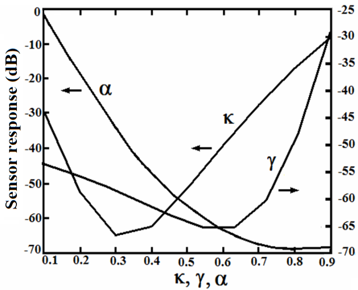 | Figure 5. The effects of   and and  on the sensor response on the sensor response |
 on the sensor response are nearly linear in the range of 0.1 to 0.6. Therefore, the variations of
  may also be a means of measurements of physical quantities. As it is shown, over the best linear range of
  (from 0.1 to 0.6), a detectable variation of -70 dB in the sensor response is observed.
5. Conclusions
- By using a fiber-optic ring resonator, a nano-scale sensor for possible measurements of physical quantities is proposed and its performances are analyzed in terms of characteristic parameters of the ring resonator. The theoretical analysis shows that if a physical quantity, such as under-water acoustic wave, causes a step change of 100 nm in the resonance loop length, the sensor response would be linear and detectable. In addition, it is shown that by changing the transmission coefficient of the resonance loop via a physical quantity in the range of 0.1 to 0.6, the variations of the sensor response would be linear, which may also be used as a criterion for measurement of physical quantities. The theoretical results also show that the slope angle of the sensor response changes with applied measurand field. The measurable change may be as low as 100 nm. It is worthy to mention that the proposed sensor configuration, based on fiber-optic ring resonator, is presented for the first time, which of course requires more theoretical investigations with an experimental data supports. However, the results of this analysis may be used in design of hydrophones utilized in submarine communications.
 Abstract
 Reference
 Full-Text PDF
 Full-Text HTML