Vamara Dembele, Khalid Assid, Faiçal Alaoui, Abdel Karim Nassim
Laboratoire Instrumentation de Mesure et de Contrôle, Equipe Métrologie Optique et Traitement Image, Université Chouaib Doukkali-FSJ, BP 20 El Jadida 24000, Morocco
Correspondence to: Khalid Assid, Laboratoire Instrumentation de Mesure et de Contrôle, Equipe Métrologie Optique et Traitement Image, Université Chouaib Doukkali-FSJ, BP 20 El Jadida 24000, Morocco.
| Email: |  |
Copyright © 2012 Scientific & Academic Publishing. All Rights Reserved.
Abstract
The purpose of the present work is the use of the Phase evaluation CWT algorithm to extract the phase from squeezing interferogram. The squeezing interferometry technique generates a spatial carrier interferogram named squeezed interferogram by numerical combination of M shifted fringes patterns. The M shifted fringes patterns are digitally generated from combination of two π/2 shifted fringe patterns. From squeezed interferogram the phase is extracted in wavelet domain using CWT algorithm which leads directly to the phase distribution without the complex step of phase unwrapping. Simulated fringe pattern are used to test our technique and real fringe pattern are used to improve the accuracy of this technique.
Keywords:
Optical Phase Interferometry, Squeezing Interferometry, Phase Evaluation Algorithm, CWT Wavelet Transform
Cite this paper: Vamara Dembele, Khalid Assid, Faiçal Alaoui, Abdel Karim Nassim, Squeezed Carrier Interferogram for Wavelet Phase Recovery, International Journal of Optics and Applications, Vol. 2 No. 4, 2012, pp. 38-42. doi: 10.5923/j.optics.20120204.02.
1. Introduction
Many whole field optical techniques provide the measurement data encoded as the phase of a periodic intensity profile. The obtained image is called a fringe pattern. The fringe pattern analysis generally consists of the phase evaluation methods[1, 2] employed to measure various physical magnitudes in variety of scientific and engineering fields. The phase evaluation methods can be classified as methods without a spatial carrier such as the phase shifting methods[3-5] and methods with a spatial carrier such as the Fourier transform method[6, 7] and the wavelet method[8, 9]. For the wavelet phase extraction algorithm, the spatial carrier is introduced digitally and the entire process is carried out directly in the computer[10]. A high potential accuracy is attained when the carrier frequency value is conveniently selected[11]. It is not evident to have easily such a value, especially for experimental fringe patterns. The aim of this work is to determine optical phase distribution from spatial carrier interferogram named squeezed interferogram in the wavelet domain. The squeezing interferometry technique[12] generates a squeezed interferogram by numerical combination of M shifted fringes patterns. Several techniques have been used successfully in fringe pattern demodulation[13]. In this paper we propose to use continuous wavelet transform CWT[14, 15] to demodulate this carrier interferogram. It leads directly to the phase distribution avoiding the complex step of phase unwrapping.The paper is organized as follows. Section 2 contains the digital M shifted fringes patterns generation. We then presented the Squeezing Interferometry Technique in section 3. Section 4 is devoted to phase evaluation by wavelet transform analysis. Computer simulation and experimental results are exposed in sections 5 and 6 respectively. Finally, conclusion is presented in section 7.
2. Synthetic Shifted Fringe Patterns Generation
The intensity of the interference pattern is formulated by the sinusoidal dependence on the spatial coordinates (x, y) of the image plane | (1) |
Where A(x, y) is the background. The term B(x,y) is the modulation intensity and ϕ (x, y) is the optical phase.In our work, we will generate numerically multiple interferogram with known phase-shift amount between them from only two π/2 shifted interferograms.The cosine fringe pattern is | (2) |
The π/2 shifted fringe pattern is | (3) |
After removing the background A(x,y) by a high pass filter, the resultant fringe patterns are: | (4) |
 | (5) |
We propose to combine numerically the interferogram and its quadrature
  with cos(β) and sin(β) respectively which leads to the β shifted fringe pattern
 | (6) |
 | (7) |
By this way, numerical generation of multiple shifted interferograms with desired phase steps, from only two primary interferograms, will enable us to have a single blended carrier interferogram by squeezing technique.
3. Squeezing Interferometry Technique
The principle of squeezing interferometry[12] is based on transforming M temporal-spatial phase shifted fringe patterns by a blending technique into a single carrier fringe pattern and then demodulating this carrier interferogram to retrieve the phase.Squeezing interferometry rearranges the data of M shifted interferograms with size LxL to a spatial linear carrier interferogram with extended size MxLxL, which converts the temporal phase shift to the spatial carrier.A sequence of M phase shifted interferograms can be written as | (8) |
With m=0, 1,…M-1. The normalized phase shift frequency f=1/M and the phase shift step is
is  | (9) |
Squeezing interferometry rearranges the data of the M interferograms to obtain the squeezed frequency carrier interferogram by: | (10) |
Intermixing the M fringe patterns by this squeezing technique, we obtained a squeezed fringe pattern . The fringe pattern representation of this re-arrangement is defined by
 | (11) |
With x'=1, 2,…MxL and φ(x',y) is the unknown phase.The  added phase to the phase of interest is known as the phase modulated carrier. In previous works, the choice of the spatial carrier was a critical step since it was governed by the following condition:
  | (12) |
The condition in Equation 12 cannot lead automatically to the suited value of . This problem was avoided by the use of squeezing interferometry technique which leads easily to suitable values of
 .Ones constructing the squeezed interferogram as in Equation 11, it is easy to demodulate the phase by a wider range of Interferometric techniques such as wavelet or Fourier techniques. In this paper, we present a phase evaluation method, based on Paul wavelet algorithm, which directly yields the phase gradient from the squeezed fringe pattern. The spatial phase distribution being obtained by integration of the gradient; there is no need to perform phase unwrapping
4. Wavelet Optical Phase Extraction
Wavelets offer a powerful method to quantify how energy is spatially distributed at multiple scales[14]. A good review of wavelet theory has been published by Daubechies[15].In this study, the phase mapping of the fringe pattern is obtained by wavelet phase evaluation method[8]. From a carrier fringe pattern, the continuous wavelet transform is used to extract the localized spatial frequencies. The phase gradient is performed simply from the modulus of the wavelet transform by extracting the extremum scales. The phase distribution is obtained by integration.The one-dimensional wavelet transform of the carrier fringe pattern intensity, in the x’ direction, is given by | (13) |
Where βx’ is the phase modulated carrier and ψ*s,ξ(x’) is the conjugate analyzing wavelet obtained for the shift ξ and the scale s.Exploiting the wavelet localization property and assuming a slow variation of the modulation intensity, the wavelet transform becomes | (14) |
By introducing Paul mother wavelet of order n[8] formulated by | (15) |
And using Parseval identity, the modulus of the wavelet transform is equal to | (16) |
Where m1 is the localized spatial frequencies given by | (17) |
The phase gradient is performed simply from the modulus of the wavelet transform by extracting the extremum scales S. | (18) |
This leads to the phase by integration.
5. Computer Simulation Results
To evaluate the performance of our method, the following phase distribution was simulated | (19) |
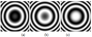
The intensity distribution of fringe pattern of size of 256x256 pixels shown in Figure 1(a) is given by the equation | (20) |
In the following, we present the results given for M=3. | Figure 1. the cosine and sine fringes patterns by numerical simulation |
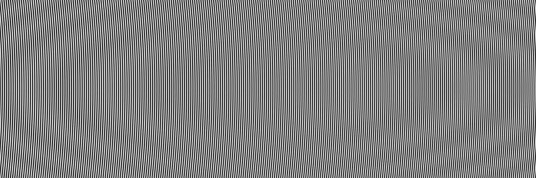
 | Figure 2. the synthetic fringes pattern generated from the cosine and sine fringes patterns, are shifted by β=2π/3 |
 | Figure 3. the squeezed fringe pattern obtained by the squeezing technique |
The sine fringe pattern is depicted in Figure1(b). The fringes pattern generated synthetically from the two fringes pattern are shown in Fig.2. The carrier fringe pattern is shown in Fig.3 where the carrier value is β=2π/3.To evaluate the performance of phase evaluation methods, we have calculated the fidelity f defined by | (21) |
Where Iideal is the ideal simulated phase and I is the retrieved phase. The fidelity quantifies how well image details are preserved. A fidelity value close to 1 will indicate that the retrieved phase is similar to the simulated one. The retrieved phase and the simulated phase are depicted in Figure 4(a) and 4(b), the fidelity value is 0.925.To inspect the M effect on the sensitivity of our method, we conducted a study on different simulated fringe patterns. For different values of M; it was found that the best results were achieved when M=9.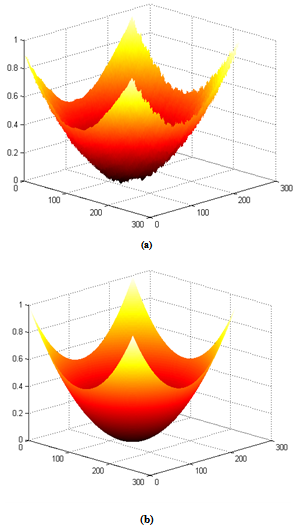 | Figure 4. (a) the retrieved phase, (b) the simulated phase |
All the results are summarized in Table 1, we can clearly see that the fidelity f presents the best values when M=9.| Table 1. Fidelity values for different simulated phases and different values of M |
| | | M=3 | M=5 | M=7 | M=9 | M=11 | | Phase 1 | 0.925 | 0.970 | 0.973 | 0.996 | 0.979 | | Phase 2 | 0.586 | 0.972 | 0.979 | 0.986 | 0.982 | | Phase 3 | 0.614 | 0.873 | 0.873 | 0.898 | 0.891 | | Phase 4 | 0.802 | 0.961 | 0.965 | 0.975 | 0.953 | | Phase 5 | 0.671 | 0.972 | 0.980 | 0.984 | 0.981 |
|
|
In Fig.5 we illustrated the simulated fringe patterns used on Table 1 and the corresponding obtained phases for M=9.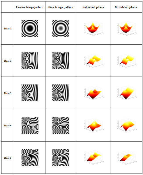 | Figure 5. Results obtained for various simulated phases when M=9 |
6. Experimental Results
To illustrate the use of our method for real applications, we tested its performance on a rough ground finish, aluminium surface from a hard disk drive assembly. Changes were induced by tilting the surface and recording interferograms before and after. Figure 6 shows the two-π/2 shifted fringe patterns with 9 fringes of tilt.A comparative study was conducted for different values of M. Compared to the Phase Shifting Algorithm results; the retrieved values for f are presented in table 2. Here again; 9 synthesized frames are the most suited to construct the squeezed interferogram shown in Figure 7 that leads to the phase with a high accuracy.| Table 2. Fidelity values for different values of M. |
| | | M=3 | M=5 | M=7 | M=9 | M=11 | | F | 0.992 | 0.993 | 0.993 | 0.994 | 0.993 |
|
|
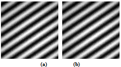 | Figure 6. (a). the cosine Fringe pattern for an aluminium transducer suspension assembly from a hard disk drive that was tilted between measurements. (b). the corresponding sinus fringe pattern |
 | Figure 7. the squeezed fringe pattern obtained for M=9 |
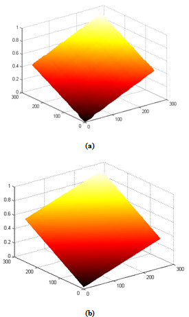 | Figure 8. (a). Retrieved phase using our method for M=9, (b). Retrieved phase with Phase Shifting Algorithm |
As it is shown in figure 8(a) and figure 8(b); the result is of the same order of accuracy to DSPI measurements using the Phase Shifting Algorithm. It is worth noting that our method gives the phase distribution without unwrapping and from only two-π/2 shifted interferograms
7. Conclusions
In this paper, we have presented a method for phase recovery from squeezed fringe pattern with carrier value β= 2π/M using the wavelet phase evaluation method. From two π/2 fringe patterns, we generated numerically M shifted fringe patterns. Combining the M shifted fringe patterns by squeezing interferometry technique; we obtained a spatial carrier interferogram. Applying the wavelet phase evaluation method, we have obtained the phase distribution with a good accuracy avoiding the complex step of phase unwrapping and the critical conveniently frequency carrier selection.
ACKNOWLEDGEMENTS
We want to thank Dr Joseph W. Goodman for his constructive and helpful comments. We also want to thank Dr Neal Brock and Dr J. C. Wyant from 4D technology© for providing us the experimental shifted fringe patterns.
References
| [1] | SR. Sirohi, SF. Chau, ‘Optical Methods of measurement’, Marcel Dekker Inc. (1999) |
| [2] | VB. Dorrio, LL. Fernandez, ‘Phase- evaluation methods in whole-fields optical measurement techniques’, Meas. Sci. Technol., Vol. 10, pp.33-55 (1999) |
| [3] | K. Creath, ‘Phase – measurement interferometry techniques’, In Wolf E (ed.): Progress in optics Vol. XXVI. pp. 349–393 Elsevier Science, Amsterdam (1988) |
| [4] | G. Lai and T. Yatagai, ‘’Generalized phase-shifting interferometry’’, J. Opt. Soc. Am. A 8, 822–827 (1991). |
| [5] | D. Malacara, S. Manuel, and M. Zacarias, ‘Interferogram Analysis for Optical Testing’, 2nd ed., Optical Engineering and Science Taylor & Francis, (2005) |
| [6] | MS. Takeda, S. Kobayashi, ‘Fourier transform methods of fringe pattern analysis for computer based topography and Interferometry’, Opt. Soc. Am, Vol. 72, pp.1156-1160 (1982) |
| [7] | K. Freischland and C. L. Koliopoulos, “Fourier description of digital phase measuring interferometry,” J. Opt. Soc. Am. A 7, 542-551 (1990) |
| [8] | M. Afifi, A. Fassi-Fihri, M. Marjane, K. Nassim, M. Sidki, S. Rachafi, ‘Paul wavelet based algorithm for optical phase distribution evaluation’, Opt Commun, Vol. 211, pp. 47-51 (2002) |
| [9] | L. R. Watkins,“Phase recovery from fringe patterns using the continuous wavelet transform,” Opt. Lasers Eng., vol. 45, pp 298–303 (2007) |
| [10] | E.M. Barj, M. Afifi, A.A. Idrissi, S. Rachafi, K. Nassim, ’A digital spatial carrier for wavelet phase extraction’, Optik - International Journal for Light and Electron Optics, Vol. 116, Issue 11, 17, pp. 507-510 (2005) |
| [11] | K. Assid, F. Alaoui, V. Dembele, S. Houmairi, M. Sidki, A. Nassim, ‘Normalized Hilbert Huang Transform-NHHT applied to Phase extraction in Wavelet Domain’ The Open Optics Journal, Vol. 6 (2012) |
| [12] | M. Servin, M. Cywiak, D. Malacara-Hernandez, J. C. Estrada, and J. A. Quiroga, ‘Spatial carrier interferometry from M temporal phase shifted interferograms: Squeezing Interferometry’, Opt. Express 16(13), pp. 9276–9283 (2008) |
| [13] | Q. Kemao, ’Windowed Fourier transform for fringe pattern analysis’, Applied Optics, Vol. 43, No. 13, (2004) |
| [14] | Kaiser G. ‘A Friendly Guide to Wavelets’, Birkhauser: Boston; (1994) |
| [15] | Daubechies I. ‘Ten Lectures on wavelets’, society for industrial and applied mathematics. Philadelphia: PA; (1992). |


 and its quadrature
  with cos(β) and sin(β) respectively which leads to the β shifted fringe pattern


 is
is 

 . The fringe pattern representation of this re-arrangement is defined by
 added phase to the phase of interest is known as the phase modulated carrier. In previous works, the choice of the spatial carrier was a critical step since it was governed by the following condition:
 . This problem was avoided by the use of squeezing interferometry technique which leads easily to suitable values of
 .Ones constructing the squeezed interferogram as in Equation 11, it is easy to demodulate the phase by a wider range of Interferometric techniques such as wavelet or Fourier techniques. In this paper, we present a phase evaluation method, based on Paul wavelet algorithm, which directly yields the phase gradient from the squeezed fringe pattern. The spatial phase distribution being obtained by integration of the gradient; there is no need to perform phase unwrapping


 Abstract
 Reference
 Full-Text PDF
 Full-text HTML