-
Paper Information
- Next Paper
- Paper Submission
-
Journal Information
- About This Journal
- Editorial Board
- Current Issue
- Archive
- Author Guidelines
- Contact Us
International Journal of Optics and Applications
2012; 2(4): 34-37
doi: 10.5923/j.optics.20120204.01
Confinement Loss and GVD for HF and AHAOF by FEM
 Abstract
 Reference
 Full-Text PDF
 Full-Text HTML
Akbar Zendehnam , Mahmoud Mirzaei , Razieh Solgi
Department of Physics, Faculty of Science, Arak University, Arak, 38156-8-8349, Iran
Correspondence to: Akbar Zendehnam , Department of Physics, Faculty of Science, Arak University, Arak, 38156-8-8349, Iran.
| Email: |  |
Copyright © 2012 Scientific & Academic Publishing. All Rights Reserved.
An analysis of the confinement loss and Group Velocity Dispersion (GVD) due to their importance is performed by means of the finite element method for two kinds of fibers, an Air-Hole Assisted Optical Fiber (AHAOF) and a Holy Fiber (HF). Both structures are based on a subset of a triangular array of cylindrical air holes; the cross sections of these inclusions are circular and the refractive index of the AHAOF core is higher than clad, and a missed central hole forms the HF core. The group velocity dispersion shows different behaviours in different ranges of wavelength also numerical results which we obtained agree well with the results of the other reported methods for HF dispersion but the results of the AHAOF dispersion were different from the outcome of the finite difference method for this fiber. The numerical results indicate that confinement loss increases with increasing wavelength and they show that the confinement loss of AHAOF is higher than HF because the smaller air holes in structure of HF can confine fields in the core region more than AHAOF.
Keywords: Finite Element Method, Group Velocity Dispersion, Photonic Crystal Fibers
Article Outline
1. Introduction
- Photonic crystal fibers (PCFs) guide the electromagnetic field by means of an arrangement of air holes that run down the entire fiber length. In the holy fibers the air holes reduce the average refractive index around the solid core and guidance can be ascribed by total internal reflection. Conversely in the photonic band gap fibers the average core index could be lower than the average cladding index and the guidance is due to the photonic band gap in the transverse direction. One of the appealing characteristics of such fibers is that their dispersion and modal properties can be controlled significantly by varying the size (diameter) of the air-holes, their number, and their positions[1]. In both cases a lossless propagation is possible only if the air hole arrangement is of infinite extent and, of course, if a lossless material is used. A fiber can be considered as confinement lossless if the field leakage is negligible with respect to the material losses. To investigate leaky modes properties, in order to find guidelines for the design of lossless fibers, numerical models with proper boundary conditions must be adopted. In fact, periodic boundary conditions or perfect electric or magnetic conductor boundary conditions which usually are employed in the numerical models affect the transverse Poynting vector flow of the numerical solutions.Among the full vectorial methods used in modelling PCFs[2–7], the finite-element method (FEM) is particularly effective for handling curved interfaces with high accuracy, and it is obviously a good choice for the analysis of combined circular and elliptical shapes. The numerical method used in this study is FEM which is adequate and suitable for the analysis of general dielectric waveguide geometries. Although it has complicated equations to solve and needs to spend long time, it is more accurate than the other methods[8-11]. It has been already successfully applied to investigate dispersion properties of triangular and cobweb PCFs[12]. The fiber cross-section representation is very accurate as the domain is divided into subdomains with triangular or quadrilateral shapes, where any refractive index profiles can be properly represented. Applying the variational FEM procedure to the curl-curl equation for magnetic field H, one obtains an eigenvalue equation (1) [12]:
 | (1) |
 is the global magnetic field vector,
  is the propagation constant, and
  and
and  are both sparse matrices. The symmetry of the fiber cross-section is exploited to reduce CPU time and memory requirements. Solving the eigenvalue equation yields the effective indices of guided modes
 , where
  is the wave vector in free space.
2. Results and Discussion
2.1. Air-Hole-Assisted Optical Fiber (AHAOF)
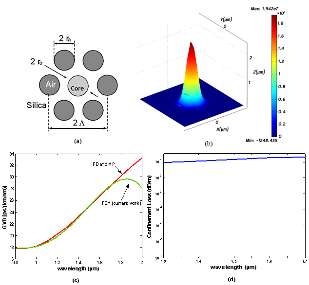 | Figure 1. (a)Schematic of an air-hole assisted optical fiber(Core index 1.45, silica cladding index1.42,  , ,  , ,  ,); (b)Magnetic field plot of the fundamental mode (y-polarization); (c)Calculated GVD curve (material dispersion not considered); (d)Calculated confinement loss curve, against wavelengths ,); (b)Magnetic field plot of the fundamental mode (y-polarization); (c)Calculated GVD curve (material dispersion not considered); (d)Calculated confinement loss curve, against wavelengths |
 ,
,  and n =1 (for air holes).While it is trivial to take into account the material dispersion by changing the refractive index at each wavelength, small differences in GVD between different approaches are better appreciated by excluding material dispersion. As for this figure, the GVD is constant at low wavelengths (
 ) and afterward increases linearly with a sharp slope up to about 1.7µm, then the plot related to the FEM starts to decrease with wavelength but for other methods continues to increase. It is predicted that this behaviour is because of the dimension of the air holes are getting close to wavelengths (for
 ). In Figure 1(d) the variation of the confinement loss against wavelength (1300-1700nm) for AHAOF is given, which is increasing linearly with smooth slope.
2.2. Holy Fiber (HF)
- A HF (Figure 2(a), triangular array with circular air holes is shown) is analysed with the FEM. In holey optical fibers, a mode is guided if its effective mode index satisfies
 [14], where
  is the refractive index of silica, and
  is the effective index of the fundamental space-filling mode (FSM)[14, 15] of the infinite periodic cladding.
  is an important parameter in the effective index model of holey fibers, which can give estimation of the number of guided modes and the effective mode areas[16, 17]. The field plot for the fundamental mode is shown in Figure 2(b). In Figure 2(c) the curves of the calculated GVD versus wavelength from FEM and FD mode solvers and the localized function method are given. It shows that calculated GVD for all of the mentioned methods is increases with an almost sharp slope up to about 1μm wavelength and after that is roughly constant up to about 1.4μm and then start to reduce sharply. The plots reduction at higher wavelengths are not in a excellent agreement and FD method gives a lower value for GVD at
 . The confinement loss versus wavelength for this fiber is given in Figure 2(d); which is almost linear and increases with wavelength. The confinement loss of HF is less than AHAOF also its plot slope is lower in the same ranges of wavelength (1300- 1700nm), so it is more beneficial to use them (HF) in some applications which need constant or low confinement loss. Increasing the number of air hole rings affects the confinement loss of microstructure fibers generally. Although the amount of confinement loss is reduced by increasing the number of air hole rings(is illustrated in[18]) plot gradient of curves increases thus using the holy fibers with less number of ring holes even with higher confinement loss is more beneficial.
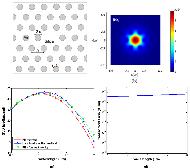 | Figure 2. (a)Calculation window of the holey fiber ( ), silica refractive index of 1.45 is assumed at all wavelengths); (b)Field plots of the y-polarized fundamental mode; (c)Calculated GVD curves; (d)Calculated confinement loss curve, versus wavelength ), silica refractive index of 1.45 is assumed at all wavelengths); (b)Field plots of the y-polarized fundamental mode; (c)Calculated GVD curves; (d)Calculated confinement loss curve, versus wavelength |
3. Conclusions
- The confinement loss and group velocity dispersion of two types of microstructured optical fibers against wavelength were demonstrated by finite element method successfully. The confinement loss of type1 (AHAOF) is higher than type2 (HF) because the smaller air holes in structure of type2 can confine fields in the core region more than type1. The calculated GVD curves for both structures are in complete adjustment to the other calculated methods. The confinement loss is a linear function of wavelength in both structures (in the communication wavelength range
 ).
).