International Journal of Optics and Applications

2012;  2(3): 20-28

doi: 10.5923/j.optics.20120203.02

Tuning of Wavelengths for Producing Eye Safe Laser Using Second Order Nonlinear Processes

Kireet Semwal1, S. C. Bhatt2

1Applied Science Department, GB Pant Engineering College, Pauri (Garhwal), Uttarakhand, India

2Department of Physics, HNB Garhwal University Srinagar (Garhwal), Uttarakhand, India

Correspondence to: Kireet  Semwal, Applied Science Department, GB Pant Engineering College, Pauri (Garhwal), Uttarakhand, India.

Email:

Copyright © 2012 Scientific & Academic Publishing. All Rights Reserved.

Abstract

We are introducing here conversion of eye hazardous laser to the eye safe region by Optical Parametric Oscillation (OPO) method, using nonlinear optical crystals. The practical optical parametric oscillator device consists of a nonlinear crystal enclosed in an optical resonant cavity pumped by Nd:YAG laser. Optical parametric devices generate broadly tunable coherent optical radiations by the phase-matching nonlinear optical interaction of an intense laser beam with this nonlinear crystal. In this process the high energy pump photon is converted into a pair of lower frequency signal and idler photons while conserving the total energy and momentum. Tunability of the signal-idler pair is usually achieved by changing the crystal birefringence of the angular dependence of the extraordinary index of the nonlinear crystal. The output energy is an eye safe radiation at either, or both the signal and idler wavelengths.

Keywords: Optical parametric oscillation (OPO), nonlinear optics, Phase Matching, Eye safe Laser

1. Introduction

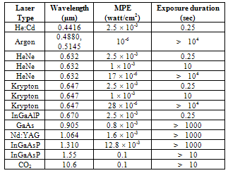
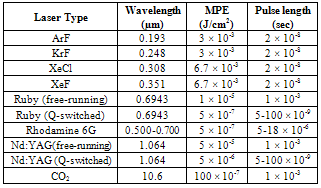
Laser application have proliferate in recent years and, as to be expected, their presence is no longer confined to the laboratory or places where access to their radiation can be controlled. One obvious application where this is so, is Military operations where various devices such as laser range finders, target designators, and secure communications equipment elevate the risk of exposure, specifically eye exposure, to unacceptable levels. Although the need for eye protection in the laboratory and other controlled areas has been appreciated since the invention of the laser, the use of lasers in circumstances where safety or the risk of loss of vision, has made adequate eye protection essential. It is found that laser with operating wavelengths in the region of approximately 0.4 µm to 1.4 µm (i.e. visible and near infrared) is the eye hazardous portion of optical spectrum, because in this region it is transmitted by the cornea and the lens serves to focus the laser beam on the retina. Thus, the actual laser power density entering the eye can be increased by some 105 by the time the light gets to the retina, and burn it without any time lag. This hazardous wavelength region often called ocular focus region [1]. Whereas wavelengths beyond this region are absorbed in the cornea, lens, and vitreous humor of eye, and therefore laser cannot make direct impact on the retina. In this region our eye is relatively safe, and there is only thermal injury to eye. Therefore retinal damage is often more severe than corneal damage.
Eye damage may not only result from laser light coming directly from the laser, but may also by light coming from secondary light path i.e. reflection, refraction, scattering etc. For extremely high-power laser, even diffuse reflections may be capable of causing eye damage [2] [3].
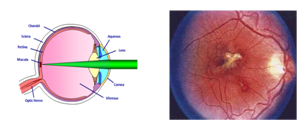
Figure 1. Construction of eye and eye injury by laser
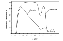
Figure 2. Eye transmission and absorption
The effect of pulsed lasers is dependent on the intensity and duration of the pulse. For the same energy output the hazards due to Q-switched or mode-locked lasers are generally greater than pulsed outputs at the same energy output. Maximum permissible values of exposure (MPE) based on damage to the retina, derived from measurements of damage over the visible region, are given in table-1 for cw laser and in table-2 for pulsed laser [4-6].
Outside the visible light region below a wavelength of about 0.4μm the safe exposure level recommended by BS4803 (British Standard) should not exceed 130 J/m2 per day, or 2.16 W/m2 for 1 minute, or a corresponding higher density over a shorter period. At infrared wavelengths above about 1.4 μm the maximum density from a single pulse should be limited to 1kJ/m2 and for continuous exposure the average level should be limited to 500 W/m2 [5]. Maximum exposure levels at the skin, excluding the eye, are taken as the same for all lasers at 1kJ/m2 for a single pulse and 1kW/m2 for continuous exposure.
Table 1. Ocular MPE values for cw laser
     
Table 2. Ocular MPE values for pulsed laser
     
The American National Standards Institute (ANSI) Standard Z136 [5] gives maximum permissible exposure (MPE) levels for different lasers and modes of operation. The MPE is based on power intensities corresponding to a factor of 10 less than the level at which a 50 per cent probability of causing ocular damage exists.The ANSI Standard is very comprehensive, covering the entire optical spectrum, and anticipates almost every possible contingency, including MPE levels for the eye and body, for direct and indirect exposure, for various pulse and exposure durations including single pulse, repetitively pulsed, and cw operation. The MPE are generally higher than those proposed by BS4803, except for pulses of short duration. The most important thing to notice that the maximum permissible exposure numbers are really very small! The second most important thing to notice is that pulsed lasers are a good deal more dangerous (lower MPE) than continuous wave (cw) lasers [3].
During the last many years much effort have been made to develop eye safe lasers (i.e. using materials such as Er:YAG, Er:glass etc.), basically for rangefinders using single pulse of very high intensity, but at a eye-safe wavelength [4]. With lasers of this eye safe kind, range measurement capabilities of 10 km or more have been obtained. The main disadvantage of these rangefinders is their complexity, power efficiency and reliability [5]. Nd:YAG laser removes most of these discrepancies and therefore used as a superior rangefinder. The only problem in using Nd:YAG laser is, its emission in ocular region (i.e., 1.064 μm). Which is particularly in the near infrared region, where the laser often significantly powerful. Thus it is possible to acquire severe retinal damage from a laser beam that we cannot see. Optical parametric oscillation (OPO) is a device to convert this eye hazardous radiation into the safe region.
Optical parametric devices generate broadly tunable coherent optical radiation by the phase-matched nonlinear interaction of an intense laser beam with a suitable nonlinear crystal. In this process the high energy pump photon is converted into a pair of lower frequency signal and idler photons while conserving the total energy and momentum. Tunability of the signal-idler pair is usually achieved by changing the crystal birefringence through its angular dependence of the extraordinary index of the crystal. The practical optical parametric oscillator (OPO) device is a second order nonlinear process which consists of a nonlinear crystal enclosed in an optical resonant cavity at either or both the signal and idler wavelengths and pumped by eye hazardous Nd:YAG laser.

2. Second Order Nonlinear Processes:

In the regime of conventional optics, the electric polarization vector P is simply assumed to be linearly proportional to the electric field strength E of an applied optical wave, i.e.
(1)
where ε0 is the free-space permittivity, χ is the susceptibility of a given medium and a plot of P versus E is a straight line. The relation (1) is valid for the field strengths of conventional sources. The quantity χ is a constant only in the sense of being independent of E; its magnitude is a function of the frequency. With sufficiently intense laser radiation this relation does not hold good and has to be generalized to equation (2), which can be written in the vector form, as by a power series
(2)
where is a second – rank (linear) tensor (9 components xx, xy, xz, yx,……..), where is a third -rank (nonlinear) tensor (27 components, xxx, xxy, xxz, xyx,…….), and is a forth-rank (nonlinear) tensor (81 components, xxxx,xxxy, xxxz, xxyx,……). The values of the tensor coefficients are functions of frequency and temperature. The subscripts m, n, and o etc. denotes different frequency components, and i, j, k and l are Cartesian indices that run from 1 to 3. For small field strength the polarization is proportional to the electric field E and is accounted for by the polarizatbility tensor . All of the optics discussed so far has been linear optics encompassed in the term . This term represents optical phenomenon that are proportional to the electric field and are at the frequency of incoming wave [1][6].
The term is responsible for all of the two-wave effects. This includes second harmonic generation (two fields at ω to make one at 2ω) and parametric oscillation (one field at ω1 and other field at ω2 to create fields at ω1 - ω2 and ω1 + ω2). This also includes optical mixing, and the Pocals effect (change of index of refraction with applied electric field). The nonlinear polarization tensor vanishes in the crystals that have a center of symmetry (i.e. crystal symmetry). In these crystals second harmonic generation is not possible. As a result of, many of the components of will be zero or equal to other components of the tensor. Thus the second-order polarization and the corresponding monochromatic components of the optical field:
(3)
where denotes the second-order susceptibility that is a third-order tensor. Desmond [7] simplified , and replaced by a nonlinear optical coefficient dil (Coulomb/Volt2), according to the following relationship:
(4)
i.e., the nonlinear optical coefficient dijk is symmetric in j and k and according to Khun[1] , here,ε0, is the permittivity of free space, some authors excludes ε0 from the d coefficient, in this case d [As/V2] = 8.855 10-12 d [m/v]. The conversion from the cgs system to MKS units becomes d [As/V2] = 3.68 10-15 d [esu]. In most practical situations the tensor equations containing dijk can be simplified to non-tensor form in which dijk is replaced by deff, is the effective nonlinear coefficient for the interaction dependent on crystal symmetry and propagation direction in the medium.

2.1. Second Harmonic Generation:

The simplest second-order process is that of second-harmonic generation (SHG). In this process, an intense laser beam of angular frequency ω1 (= ω) is passed through a crystal having nonzero value of , such that the beam emerging from the crystal contains the angular frequencies ω1 of the input beam and also ω2 = 1, twice the frequency of the input beam. This can be shown to occur by considering the second order nonlinear polarization term . Under certain conditions (like phase matching), it is possible to covert nearly all of the original frequency of the beam to the second harmonic frequency. Thus, second harmonic generation is a process where a wave at frequency ω is converted into one at frequency 2ω. The second-order nonlinear effects can occur in the non-centrosymmetrical crystals only [8]. In the dielectric dipole approximation, isotropic media and centrosymmetrical crystals cannot be used to generate second-order nonlinear effects. Therefore, the media for SHG should be the crystals having no inversion symmetry. This requirement is the same as that for the piezoelectric effect; thus all SHG crystals are piezoelectric crystals although the physical mechanisms for these two effects are not related to each other.
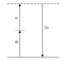
Figure 3. Second harmonic generation
Figure-3 shows the energy-level diagram for a simple picture of second harmonic generation. However, it can also be consider from the photon standpoint. In Figure two photons of the fundamental frequency ω, each with energy ħω, combining to produce energy 2ħω. The energy levels ħω and 2ħω are shown in dashed lines because they are not eigen states of the material in which the second harmonic radiation is generated but are instead levels of the combined material-photon beam system. In that sense they are known as virtual levels, since they are not levels that accrue population. Instead, two photons of frequency ω are destroyed and one photon of frequency 2ω is simultaneously created, as indicated in figure. The most common application is in the conversion of near-infrared light (such as 1.064 μm of an Nd:YAG laser) into visible light (such as green at 532 nm).
Optical second harmonic generation was first demonstrated by Franken in 1961[9]. In 1962, Armstrong et. al.[10] wrote their seminar paper “Interaction between Light Waves in a Nonlinear Dielectric”. Which include optical second harmonic generation as one of the many analyzed cases. In 1962, Maker et. al.[11], first observed the oscillation of second harmonic generation with crystal length. The concept of phase matching were proposed in 1962 by Kleinman[12] and Maker et. al.[11]. The phase matching condition for second harmonic generation is
(5)
Here, n1 is the index of refraction at ω and n2 is the index of refraction at 2ω, λ1 is the wavelength of the fundamental wave, and Δk is called the phase mismatch factor that is proportional to the refractive index difference at frequency ω and 2ω. This factor plays a very important role in the processes of nonlinear multi-wave mixing. In general, the refractive index of a medium is always a function of frequency (dispersion effect), i.e., n1n2; only in some special cases we may have n1 = n2.

2.2. Optical Sum, Difference Frequency Generation & Optical Parametric Oscillation

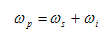
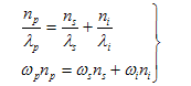
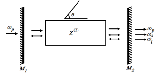
In the second-harmonic generation, considered the combination (addition) of two photons of the same frequency to produce a single photon of twice the frequency. It can now to generalize this process to allow for the case in which the two photons have different frequencies ω1 and ω2. These include second harmonic terms (involving 2ω1 and 2ω2), and two new terms involving ω1 + ω2 and ω1 - ω2. The new term involving ω1 + ω2 generates a new frequency that is the sum of the two original frequencies and is thus known as sum frequency generation. The term involving the difference between the two frequencies, ω1 - ω2 , is referred to as difference frequency generation. In the process of difference frequency mixing, the frequency ω2 is amplified while the frequency ω3 is being generated. In the process of optical parametric oscillation (OPO) the intense input laser beam at frequency ωp is known as the pump frequency, when passes through a nonlinear material, generates the desired frequencies ωs (signal frequency) and the frequency ωi (idler frequency) [13] shown in Figure-4.
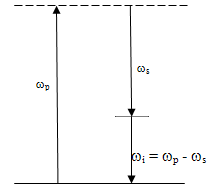
Figure 4. Optical parametric oscillation
The amplification can be enhanced by placing the optical harmonic (nonlinear) crystal within an optical cavity in which the mirrors are specifically made reflective at either one of these two frequencies, or for both. Thus the intensity at those frequencies will build up within the cavity, by Fabry-Perot interferometer. Such an amplification process is known as an optical parametric oscillator (OPO). Of course, either ωs or ωi can be tunable laser to generate amplified tunable output. This process is used most often in the infrared frequency range, where tunable lasers are not as readily available as in the visible portion of the frequency spectrum [14]. The output of an optical parametric oscillator (OPO) is similar to that of a laser. The energy conservation requires that
(6)
Here ωp, ωs, and ωi are the frequencies of the pump, signal and idler wave. For a given ωp, there can be a continuous range of choices of ωs and ωi. This, in fact, is the origin of the tunability of the optical parametric oscillator. The specific pair of frequencies that will be emitted is dictated by the momentum conservation condition, or phase matching condition: kp = ks + ki, that must also be satisfied in order to ensure that the signal waves generated in different parts of the nonlinear crystal are in phase and add coherently [15]. For collinearly propagating waves this may be written
(7)
Here np, ns and ni are the refractive indices of the pump, signal and idler wave and λp, λs and λi there corresponding wavelengths respectively. The pump signal is usually provided by a laser and, therefore λp is fixed. However, if the refractive indices are varied, the signal and idler frequencies will tune.
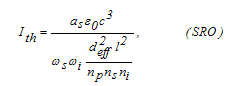
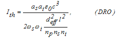
Figure 5. Singly-Resonant Optical Parametric Oscillator
Under an appropriate arrangement for the angle (or temperature) of a given nonlinear crystal, the above two requirements (Eq. (6) & (7)) can be satisfied and oscillations at two different frequencies ωs, and ωi can be achieved. Based on this working condition, if we slightly change the angle of the crystal, the refractive index relation between these three waves will be changed; therefore the oscillating frequencies will be smoothly tuned to different values [16][17]. After passing through the output-coupling mirror the transmitted pump beam is blocked by a filter. The further separation between the signal beam and idler beam can be done by using appropriate spectral filters or optical dispersive elements. Various optical cavity designs, including stable, unstable, or metastable cavity configurations, can be employed for OPO purpose. The criteria of selection of cavity designs are same as that for laser cavity devices [11].
The requirements of nonlinear crystals for optical parametric oscillation are essentially the same as that for SHG. In other words, the nonlinear materials must be non- centrosymmetrical crystals, highly transparent for pump, signal, and idler beams, able to fulfill the phase matching by using angle-tuning or temperature-tuning. In principle, all commonly used SHG crystals used for OPO purpose. A possible simple implementation of the optical parametric oscillator is shown schematically in Figure-5.The OPO consists of a suitably oriented nonlinear optical crystal in a Fabry-Perot cavity. The cavity mirrors are coated to transmit the pump wave and reflect either the signal wave only or both the signal and idler waves. In the former case, the oscillator is known as the singly resonant oscillator (SRO), and, in the latter case, it is known as the doubly resonant oscillator (DRO). The threshold for oscillation of the singly resonant oscillator is [17-19]
(8)
and that for the doubly resonant oscillator is
(9)
where Ith is the threshold intensity; as and ai are the fractional round-trip power losses of the signal and idler waves; deff is the effective nonlinearity of the OPO crystal; l is the crystal length; np, ns, and ni are the refractive indices of the pump, signal, and idler waves, respectively; ε0 is the permittivity of free space, and c is the speed of light. Clearly, the threshold for the singly resonant oscillator will be higher than that for the doubly resonant oscillator. The threshold pump intensity Ith for a singly resonant OPO having a reflection of the pump beam from OPO output coupler is given by [20][21][22]
(10)
where
(11)
is the coupling constant, tp is the pulse width (FHWM) of the pump pulse, and γ = 1(at threshold) is the ratio of the backward to forward pump amplitude in the OPO cavity, 2αL is the round trip loss of the OPO crystal (≈ 0.01), L is the optical length of OPO cavity, leff is the effective length of the nonlinear crystal, R is the output coupler reflectivity, gs is the mode coupling coefficient (≈ 0.85), np, ns and ni are the refractive indices of pump, signal and idler wavelengths (np =1.748, ns = 1.737, ni = 1.771) [20], λs and λi are the wavelengths of signal and idler waves. The effective nonlinear coefficient for the Type-II KTP crystal non-critical-phase-matching OPO is given by [23]
(12)
The difference between the refractive indices of the ordinary and extraordinary beam is known as birefringence Δn. The value of Δn is zero along the optic axis z and maximum in the direction normal to this axis. The refractive indices of the ordinary and extraordinary beams in the plane normal to the z axis are termed the principal values and are denoted by no and ne, respectively. The refractive index of the extraordinary wave ne is, in general, a function of the polar angle θ between the z axis and the vector k. It is determined by the equation [1][6][13][19][24]
(13)
For an extraordinary wave the normal to the tangent does not coincide with the wave vector k but is rotated from it by the birefringence angle or walk-off-angle:
(14)
where the upper signs refer to a negative crystal and the lower signs to a positive one.
When the phase matching is achieved by choosing a direction of propagation which is not at 900 to the crystal optic axis is called ‘critical phase matching’. When the power flow of the e-wave is not along the direction of k, the fundamental (o-wave) and the second harmonic propagate along the crystal, the power generated in the second harmonic will separate from the fundamental leading to what is referred to as ‘walk off’. For phase matching at θm = 900, φ =0 and there is no walk off. Hence when possible, 900 phase matching is desirable. This is referred to as ‘noncritical phase matching’[24-27]. According to Desmond Smith[26], having chosen a particular phase-matching geometry, which can then determine the value of deff. The value of deff can usually be optimized by adjusting the other angle that fixes the final propagation direction,, while maintaining θ = θm. Here θ is the angle of propagation with respect to the z-axis and is the angle to the x-axis in the x-y plane.

2.3. Nonlinear Optical Materials

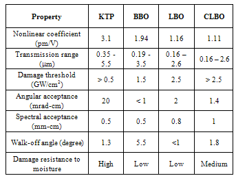
For generating new frequencies from existing lasers via harmonic generation and difference generation, they must (1) be resistant to optical damage, (2) have high mechanical hardness, (3) exhibit good thermal and chemical stability, (4) be capable of being grown in useful sizes, and (5) have the appropriate phase-matching properties. The second harmonic crystals must have no inversion symmetry (i.e. non-centrosymmetric). Bulk second-order nonlinear materials are generally inorganic crystals. A number of semiconductors are useful for second harmonic generation when used in waveguides.
The nonlinear crystals can be classified into two groups according to their physical properties. Crystals grown from water solutions are fragile, hygroscopic, and sensitive to thermal shock. The crystals of this group, to which KDP and its isomorphs belong, are somewhat difficult to handle because the crystals are soft, and the polished faces may be fogged if they are held with bare hands or exposed to humid atmosphere. On the other hand, the crystals are easy to grow, they are available in large sizes, and they are of excellent optical quality. Crystals grown from the melt are relatively hard, nonhygroscopic and less sensitive to thermal shock. Important members of this group crystals are LiNbO3 (LBO) , Ba2NaNb5O15 (BBO) and KTiOPO4 (KTP). KTP possesses good optical properties, a large acceptance angle, large temperature acceptance, a large nonlinear coefficient, and high optical damage thresholds [16][23][28][29].
Table 3. Properties of some important nonlinear crystals [27]
     
In 2001, Glenn W. Baxter et. al., reported on their paper, a singly resonant, single-axial-mode, optical parametric oscillator (OPO) based on periodically KTiOPO4. Signal (1.68 µm) and idler (2.90 µm) optical bandwidths have been narrowed to < 400 MHz by use of a diffraction grating at grazing incidence. The OPO generates 370 µJ of signal radiation when pumped by 3.1 mJ of 1.064 µn radiation [30]. Goran Hansson, et. al., in October 2001, demonstrates signal beam at 1.56 µm and idler at 3.33 µm, when RbTiOAsO4 is pumped at 1.064 µnm [31]. Kastsuhiko Miyamoto, and Hiromasa Ito, in 2007, tuned the KTP OPO by changing the crystal angle by galvano scanner, the mid IR source is tuned from approximately 5 to 10 µm at a phase matching angle of 510. While the pump wavelength was controlled in the 1.95-2.2 µm range [32]. In 2008, Wenyong Cheng, et. al., found eye safe laser at 1573 nm wavelength from a laser-diode side pumped actively Q-switched Nd:YAG / KTP intracavity optical parametric oscillator [33]. In 2010 Mikael Siltanen, et. Al., reports in their paper a continuous-wave singly resonant optical parametric oscillator pumped by a widely tunable titanium-doped sapphire ring laser. It produces up to 0.8 W of mid-infrared power. The wavelength tuned from 2.5 to 3.5 μm or from 3.4 to 4.4 μm[34]. In 2011, Markku Vainio, et.al.[35], in their paper shows wavelength tuning and stability characteristics of a singly resonant continuous-wave optical parametric oscillator (cw OPO) in the proximity of signal-idler degeneracy have been studied and M. Vainio and L. Halonen [36], studied about stable operation of a cw optical parametric oscillator near signal-idler.

3. Result & Discussion

The active laser medium consists of an antireflection-coated Nd:YAG laser rod transverse pumped by laser diode arrays. Two diode laser bars of total power 12 W transversely pumps, a 40 mm long, 5 mm diameter Nd:YAG laser rod. The diode-laser array has maximum pulse width 100 ms, repetition rate 50 Hz with a total input of 120 mJ at 808 nm from the two transverse laser diodes. Up to, 40 mJ TEM00 mode energy is obtained by Nd:YAG at 1064 nm. The 42 cm long laser cavity is formed by two Plano concave confocal mirrors, with 5 m radius of curvature. The rear mirror M1 is 100 % reflective dielectric coated for wavelength at 1064 nm whereas output coupler M2 is having 70 % reflective coating at 1064 nm. The bandwidth of laser spectra is 0.2 nm. The TEM00, mode is obtained by keeping an aperture in front of mirror M2.
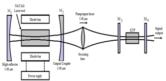
Figure 6. Schematic diagram for the Nd:YAG eye safe laser system
Since the peak absorption of YAG rod with Neodymium doping is 808.7 nm. The maximum and broad absorption bands are between 805 to 810 nm. The material for the diode laser arrays is used AlGaAs. The pump source consists of two 3 cm long electrically operated diode bars which are placed parallel to the laser rod. Each diode array has an average output power of 6 Watts for a total pump power of 12 Watts. The threshold of the laser is at 5.5 A per diode array which in turn corresponds to 4 W of diode pump power. The slope efficiency of the laser is thus approximately 33%. The current supplied to each of the diode arrays is 10 A.
The OPO consists of a 15 × 10 × 10 mm KTP crystal, placed within the 4.5 cm OPO resonator consisting plane mirrors M3 and M4. Mirror M3 is highly reflective (100 %) for the signal wavelength, while mirror M4 is 85 % reflective for the signal wavelength and highly reflective for pump and idler wavelengths. The KTP OPO is pumped by this 1064 nm, diode-pumped Nd:YAG laser with a TEM00 transverse mode. The laser beam is set normal to the z-axis (c-axis), which indicates θ = 900. The KTP crystal is cut so as to achieve type-II non-critical phase matching x-cut (θ = 900 and =00) as it maximizes effective non-linear coefficient and has large angular acceptance angles, for a pump wavelength of 1064 nm (Nd:YAG).
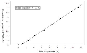
Figure 7. Output characteristics of the single transverse mode laser
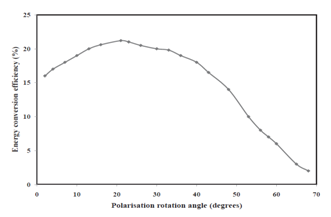
Figure 8. Conversion efficiency with the variation of angle of crystal
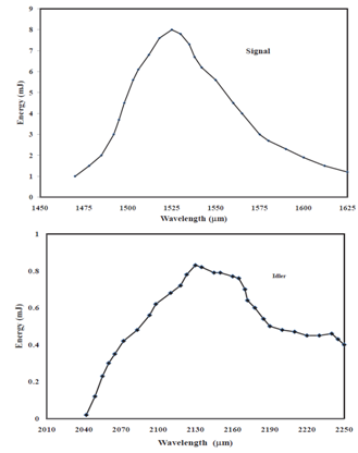
Figure 9. Variation of signal & idler energy with wavelengths
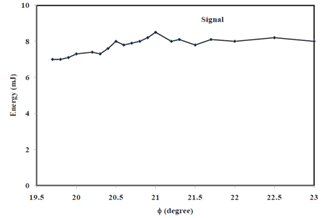
Figure 10. Signal energy at a polarization angle
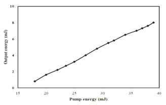
Figure 11. OPO energy as a function of pump energy
The input pump energy is fixed at 40 ± 0.6 mJ and the pump beam had a diameter of 2 mm (1/e2 intensity point), a divergence of 0.8 mrad. The largest signal energy is obtained at the point of normal incidence, at phase matching angle of θ =900 and = 210. For this configuration, the direction of propagation is along x-axis. The polarization of the pump wave and signal wave is along y-axis (o-wave) whereas idler wave is polarized in the x-z plane (e-wave). This propagation angle is very close to the value calculated using the Sellmeier coefficient for parametric generation.
It is difficult to find a signal set of Sellmeier coefficients that is accurate throughout the transparency range of a nonlinear crystal and valid for different χ(2) processes. The output energy at 1525 nm is 8 mJ, corresponding to an energy conversion efficiency of 21 %. Figure-9 shows the calculated signal wavelength as a function of phase- matching angle θ for = 0 in type-II KTP OPO pumped at 1064 nm. In the non-critically phase-matched configuration the refractive indices are ns = 1.73, np = 1.73, and ni = 1.82. The round trip loss of the OPO crystal is 2αl = 0.01, included losses due to the optical coatings on the crystal faces. The mode-coupling coefficient gs is approximately unity at threshold.
For pump wavelength of 1064 nm, it generates a signal wave at 1525 nm and idler beam at 2130 nm. The input and output faces of the KTP crystal were antireflection coated at 1064 nm and 1525 nm. For focusing the pump laser beam (1064 nm) inside the crystal a convex lens of focal length 100 cm is employed. The focused pump beam spot size within the crystal is measured to be 2 ± 0.1 mm. The OPO output principally is a signal beam at 1525 nm, it is also detected other harmonics for different orientations. This wavelength is beyond the ocular region, thus the output laser is safe for eye.

4. Conclusions

Thus Optical parametric devices generate broadly tunable coherent optical radiation by the phase-matched nonlinear interaction of an intense laser beam in a suitable nonlinear crystals such as KTP etc. In this process the high energy pump photon is converted into a pair of lower frequency signal and idler photons while conserving the total energy and momentum. Tunability of the signal-idler pair is usually achieved either by changing the crystal birefringence through its temperature dependence or by the angular dependence of the extraordinary index of the crystal.
In summary, we have demonstrated the operation of Nd:YAG eye-safe laser, pumped with two-dimensional side pumping diode-laser array. The wavelength from the Nd:YAG is 1.064 μm, which is not safe for the eye. The diode array is pulsed at 50 Hz, at power of 12 W, and energy of 120 mJ, pumpes the Nd:YAG laser operating at 1064 nm, and generates a 40 mJ pulse. A singly resonant extracavity KTP OPO pumped by this pulsed Nd:YAG laser. The output energy is an eye safe radiation at 1525 nm, with 8 mJ, corresponding to an energy conversion efficiency of 21 %, in a type-II, NCPM x-cut KTP crystal (15×10×10 mm) placed in a plane-parallel resonator. The measured OPO threshold pump intensity is in good agreement with the theoretically one. The KTP crystal is used so that when pumped at 1064 nm, it is simultaneously phase matched for optical parametric generation at the signal and idler wavelengths. The KTP crystal is cut along the θ= 900 =210 direction. The OPO output principally is a signal beam at 1525 nm, which beyond the ocular region, hence the output laser is safe for eye.

References

[1]  K. J. Kuhn; Laser Engineering, Prentice Hall Pub., 1998.
[2]  J. K. Franks; SPIE, 1419, 2-8 (1991).
[3]  L. R. Marshall, A. D. Hays, H. J. Kasinski, and R. Burnham; SPIE, 1419, 141-152 (1991).
[4]  R. D. Stultz, D. E. Nieuwsma, E. Gregor; SPIE, 1419, 64-74 (1991).
[5]  D. C. Winburn; “Practical Laser Safety”, 2d ed. (New York: Marcel Dekker, Inc. 1990.
[6]  J. Y. Huang, Y. R. Shen, C. Chen, and B. Wu; Appl. Phy. Lett., 58, 1579 (1991).
[7]  S. Desmond Smith; Optoelectronic Devices, (Prentice Hall Pub., 1995).
[8]  P. F. Moulto; Opt. Photon News, August 1990, p. 20
[9]  P.A. Franken, A. E. Hill, C. W. Peters, and G. Weinreich; Phys. Rev. Lett., 7, 118 (1961).
[10]  J. A. Armstrong, N. Bloembergen, J. Ducuing, and P. S. Pershan; Phys. Rev., 127, 1918 (1962)
[11]  P. D. Maker, R.W. Terhune, N. Nisenoff, and C.M. Savage; Phys. Rev. Lett., 8, 24 (1962)
[12]  D.A. Kleinman; Phys. Rev., 128, 1761 (1962)
[13]  W. Boyd, Non-Linear Optics (Boston, MA; Academic Press, (1992).
[14]  Qiang Liu, Bin Shi, Mali Gong, Yuezhu Wang Qi Wang; Opt. Eng. 42 (11), 3265-3269 (2003).
[15]  M. Katz, D. Eger, M. B. Oron, and A. Hardy; J. Appl. Phys., 92, 7702 (2002).
[16]  S. Wang, V. Pasiskevicius, J. Hellstrom, F. Laurell, and H. Karlsson, “First-order type-II quasi-phase-matched UV generation in periodically poled KTP”, Opt. Lett. 12, 978-980 (1999).
[17]  J. E. Bjorkholm, A. Ashkin, R. G. Smith; IEEE J. Quant. Electr. QE-6,797 (1970).
[18]  S. J. Brosnan and R. L. Byer; IEEE J. Quant. Electron. QE-15, 415 (1979).
[19]  Walter Koechner, Solid State Laser Engineering, 5rh ed., (Springer Berlin 1999).
[20]  L. R. Marshall and A. Kaz; J. Opt. Soc. Am., B10 (9), 1730 (1993).
[21]  R. Dabu, A. Stratan, C. Fenic, C. Luculescu and L. Muscalu; Opt. Eng., 40 (3), 455 (2001).
[22]  Liviu Neagu,et al, “Compact eye safe laser sources based on OPOs with KTP or PPKTP crystals”, Science Direct, Optics & Laser Technology, 39, 973-979, (2007).
[23]  S. He Guang, and H. Liu Song; Physics of Nonlinear Optics, (World Scientific Pub., 1999).[29] (Ed.), Tunable Laser Applications, 2nd Ed. (CRC, New York, 2009).
[24]  V.G. Dmitrieve, G.G. Gurzadyan, and D.N. Nikogosyan; Handbook of Nonlinear Optical Crystals (Berlin; Springer-Verlag, 1991).
[25]  M. V. Hobden; J. Appl. Phys., 38, 4365 (1967).
[26]  J. E. Midwinter, J.Warner; Brit; J. Appl. Phys., 16,1135 (1965).
[27]  H. P.Webber, E. Mathieu, K. P. Meyer; J. Appl. Phys., 37, 3584 (1966).
[28]  F. Zernike, J. E. Midwinter; Applied Nonlinear Optics (John Wiley & Sons, New York, 1973).
[29]  M. Bass, P. A. Franken, J. F. Ward, and G. Weinreich; Phys. Rev. Lett., 9, 446, (1962).
[30]  Glenn W. Baxter, Philip Schlup, Lain T. McKinnie, Jonas Hellstrom, and Fredrik Laurell, Optical Society of America, 6659-6662; 40 (36) (2001).
[31]  Goran Hansson, Halan Karlsson, and Fredrik Laurell, Applied Optics, 5446-51; 40 (30) (2001).
[32]  Kastsuhiko Miyamoto, and Hiromasa Ito, Optical Society of America, 274-276; 32 (3) (2007).
[33]  Wenyong Cheng, Schengzhi Zhao, Zhuang Zhuo, Xiaomin Zhang, Yun Wang, Optics and Lasers in Engineering, 12-17; 46 (2008).
[34]  Mikael Siltanen, Markku Vainio and Lauri Halonen “Pump-tunable continuous-wave singly resonant optical parametric oscillator from 2.5 to 4.4 μm”, Vol. 18, No. 13 / OPTICS EXPRESS 14087-14092 (2010)
[35]  Markku Vainio, Cécile Ozanam,Ville Ulvila and Lauri Halonen, “Tuning and stability of a singly resonant cw optical parametric oscillator close to degeneracy”, Vol. 19, No. 23 / OPTICS EXPRESS 22515-527( 2011)
[36]  M. Vainio and L. Halonen, “Stable operation of a cw optical parametric oscillator near the signal-idler degeneracy,” Opt. Lett. 36(4), 475–477 (2011).