| [1] | L. F. Stokes, M. Chodorow, and H. J. Shaw, “All-single-mode fiber resonator,” Opt. Lett., vol. 7, pp. 288-290, 1982. |
| [2] | G. Soundra. Pandian and Faramarz E. Seraji, “Optical pulse response of a fibre ring resonator, ” IEE Proc.-J, vol. 138 (3), pp. 235-239, 1991. |
| [3] | M. Sumetsky, Y. Dulashko, and A. Hale, “Fabrication and study of bent and coiled free silica nanowires: Self-coupling microloop optical interferometer,” Opt. Exp., vol. 12, pp. 3521-3531, 2004. |
| [4] | M. Sumetsky, “Optical fiber microcoil resonator,” Opt. Exp., vol. 12, pp. 2303-2316, 2004. |
| [5] | Huilian Ma, Shijin Wang, and Zhonghe Jin, “Silica waveguide ring resonators with multi-turn structure,” Opt. Commun., vol. 281, pp. 2509-2512, 2008. |
| [6] | N. Talebi and M. Shahabadi, “Analysis of a lossy microring using the generalized multipole technique,” Progress in Electromagnetics Research, PIER, vol. 66, pp. 287-299, 2006. |
| [7] | G. Soundra Pandian and Faramarz E. Seraji; “Analysis of a fibre-optic ring resonator with polarization effects: Application to polarization,” J. Mod. Opt., vol. 39 (5), pp. 991-1001, 1992. |
| [8] | R. W. Boyd, J.H. Heebner, “Sensitive disk resonator photonic biosensor,” Appl. Opt. vol. 40, pp. 5742-5747, 2001. |
| [9] | Sai T. Chu, B. E. Little, Wugen Pan, Taro Kaneko, Shinay Sato, and Yasuo Kokubun, “An eight-channel add-drop filter using vertically coupled microring resonators over a cross grid,” IEEE Photon. Technol. Lett., vol. 11 (6), pp. 691-693, 1999. |
| [10] | D. G. Rabus, M. Hamacher, and H. Heidrich, “Active and passive microring resonator filter applications on GaInAsP/InP,” Proc., 13th Int. Conf. on Indium Phosphide and Related Materials, IPRM, 14-18 May 2001, Nara, Japan, Pap. ThA1-3, pp. 477-480, 2001. |
| [11] | Fufei Pang, Feng Liu, Xiuyou Han, Haiwen Cai, Ronghui Qu, Zujie Fang, “Analysis of a second-order polarization-independent filter made of a single ring resonator and a Sagnac interferometer,” Opt. Commun., vol. 260, pp. 567-570, 2006. |
| [12] | Sanjoy Mandal, Kamal Dasgupta, T.K. Basak, S.K. Ghosh, “A generalized approach for modeling and analysis of ring-resonator performance as optical filter,” Opt. Commun., vol. 264, pp. 97-104, 2006. |
| [13] | P.P. Yupapin, P. Saeung, C. Li, “Characteristics of complementary ring-resonator add/drop filters modeling by using graphical approach,” Opt. Commun., vol. 272, pp. 81-86, 2007. |
| [14] | P. Saeung, P.P. Yupapin, “Generalized analysis of multiple ring resonator filters: Modeling by using graphical approach,” Optik, vol. 119 (10), pp. 465-472, 2008. |
| [15] | S. Dilwali and G. S. Pandian, “Pulse response of a fiber dispersion equalizing scheme based on an optical resonator,” IEEE Photon. Technol. Lett., vol. 4 (8), pp. 942-944, 1992. |
| [16] | Hao Shen, Jian-Ping Chen, Xin-Wan Li, Yi-Ping Wang, “Group delay and dispersion analysis of compound high order microring resonator all-pass filter,” Opt. Commun., vol. 262, pp. 200-205, 2006. |
| [17] | Y. Dumeige, C. Arnaud, and P. Féron, “Combining FDTD with coupled mode theories for bistability in micro-ring resonators,” Opt. Commun., vol. 250, pp. 376-383, 2005. (Erratum: Opt. Commun., vol. 272 p. 279, 2007). |
| [18] | P. P. Yupapin, “Coupler-loss and coupling- coefficient- dependent bistability and instability in a fiber ring resonator,” Optik, vol. 119 (10), pp. 492-494, 2008. |
| [19] | Otto Schwelb, “Crosstalk and bandwidth of lossy microring add/drop multiplexers,” Opt. Commun., vol. 265, pp. 175-179, 2006. |
| [20] | Junqing Li, Li Li, Jiaqun Zhao, and Chunfei Li, “Ultrafast, low power, and highly stable all-optical switch in MZI with two-arm-sharing nonlinear ring resonator,” Opt. Commun., vol. 256, pp. 319-325, 2005. |
| [21] | Rostami, “Low threshold and tunable all-optical switch using two-photon absorption in array of nonlinear ring resonators coupled to MZI,” Microelectron. J., vol. 37, pp. 976-981, 2006. |
| [22] | P. P. Yupapin, P. Chunpang, “An experimental investigation of the optical switching characteristics using an optical Sagnac interferometer incorporating one and two ring resonators,” Opt. & Laser Technol., vol. 40, pp. 273-277, 2008. |
| [23] | J.L.S. Lima, K.D.A. Sabóia, J.C. Sales, J.W.M. Menezes, W.B. de Fraga, G.F. Guimarães, A.S.B. Sombra, “Optical short pulse switching characteristics of ring resonators,” Opt. Fiber Technol., vol. 14 pp. 79-83, 2008. |
| [24] | S. L. McCall, A. F. J. Levi, R. E. Slusher, S. J. Pearton, R. A. Logan, “Whispering-gallery mode microdisk lasers,” Appl. Phys. Lett., vol. 60 pp. 289-291, 1992. |
| [25] | D. Garus, R. Hereth, F. Schliep, “Design considerations for Brillouin–Ringlaser gyroscopes,” in: Conf. Proc. Symp. on Gyro Tech. (DGON). Stuttgart, p. 2.0, 1994. |
| [26] | K. Kalli, D.A. Jackson, “Ring resonator optical spectrum analyzer with 20-kHz resolution,” Opt. Lett., vol. 17 (15), pp. 1090-1092, 1992. |
| [27] | B.E. Little, S.T. Chu, J.V. Hryniewicz, P.P. Absil, “Filter synthesis for periodically coupled microring resonators,” Opt. Lett., vol. 25 (5), pp. 344-346, 2000. |
| [28] | T. Kominato, Y. Ohmori, N. Takato, H. Okazaki, M. Yasu, “Ring resonators composed of GeO2-doped silica waveguides,” IEEE J. Lightwave Technol., vol. 12, pp. 1781-1788, 1992. |
| [29] | R. Adar, Y. Shani, C.H. Henry, R.C. Kistler, G.E. Blonder, N.A. Olsson, “Measurement of very low-loss silica on silicon waveguides with a ring resonator,” Appl. Phys. Lett., vol. 58 (5), pp. 444-445, 1991. |
| [30] | K. Oda, S. Suzuki, H. Takahashi, H. Toba, “An optical FDM distribution experiment using a high finesse waveguide-type double ring resonator,” IEEE Photon. Technol. Lett., vol. 6 (8), pp. 1031-1034, 1994. |
| [31] | Faramarz E. Seraji, “New methods for rotation sensing by using a two-coupler fiber-optic ring resonator,” Jap. J. Appl. Phys., Part 1, vol. 32 (4), pp. 1661-1667, 1993. |
| [32] | Faramarz E. Seraji and G. S. Pandian, “Dynamic response of a fiber optic ring resonator with sinusoidal phase modulation of the loop,” J. Mod. Opt., vol. 38, pp. 671-676, 1991. |
| [33] | G. S. Pandian and Faramarz E. Seraji, “Dynamic analysis of a fibre-optic ring resonator excited by a sinewave-modulated laser diode,” Jap. J. Appl. Phys., Part 1, vol. 29 (10), pp. 1967-1973, 1990. |
| [34] | Diqing Ying, Huilian Ma, Zhonghe Jin, “Dynamic resonance characteristic analysis of fiber ring resonator,” Opt. Fiber Technol., vol. 15, Issu. 1, pp. 15-20, 2009. |
| [35] | Faramarz E. Seraji, “Steady-state performance analysis of fiber-optic ring resonator,” Prog. Quant. Electron.(Elsevier), vol. 33, pp. 1-16, 2009. |
| [36] | Faramarz E. Seraji, “Dynamic response of a fiber-optic ring resonator: Analysis with influences of light-source parameters,” Prog. Quant. Electron. (Elsevier), vol. 33, Issu. 2-4, pp. 110-125, 2009. |
| [37] | K. Saleh, P.H. Merrer, O. Liopis, and G. Cibiel, “Optical scattering noise in high Q fiber ring resonators and its effect on optoelectronic oscillator phase noise”, Opt. Lett., vol. 37 (4), pp. 518-520, 2012. |
| [38] | Bo Chen, John Bracken, Frances Verleyen, Yong Wang, Chang-qing Xu, “Analysis of all-optical intra-cavity wavelength conversions in fiber ring resonators”, Opt. Commun., vol. 247, Iss. 1-3, pp 57-64, 2005. |
| [39] | J. A. Bracken and C. Q. Xu, “All-Optical Wavelength Conversions Based on MgO-Doped LiNbO3 QPM Waveguides Using an EDFA as a Pump Source” IEEE Photon. Technol. Lett., vol. 15, no. 7, pp. 954-956, 2003. |
| [40] | T. Mizumoto and Y. Naito, “Dependence of the output phase on the asymmetry of 3-dB directional couplers” J. Lightwave Technol., vol. 8 (10), pp. 1571-1576, 1990. |
 Abstract
 Reference
 Full-Text PDF
 Full-Text HTML
 and
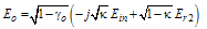
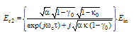
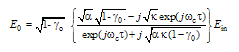
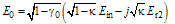
and  the electric fields of light waves at ports (1), (2), (3), and (4), respectively, the complex field amplitudes at ports (3) and (4), under steady state operation, can be expressed as[1,35].
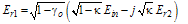
 is the power coupling coefficient of the coupler and
  is its fractional intensity loss.For an ideal condition and based on conservation of energy[35,40], the electric fields
  are related by:
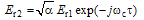
 is the loop delay time,
  is the optical angular frequency, and
  is the power transmission coefficient of the loop fiber expressed as
  , where
  is the attenuation coefficient (in dB/m) of the loop fiber, L is the length of the loop (in m).
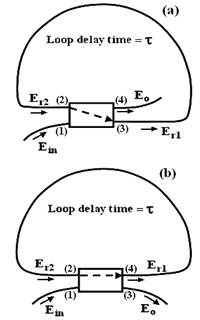
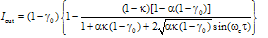
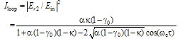
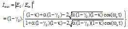
 at port (4) and the loop intensity
  at port (2) both normalized to input intensity can be shown, respectively, as:
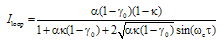
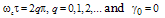
 at which the loop intensity
  builds up to a maximum value and the output intensity
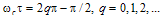
  reduces to a minimum value. By inspection of Eq. (8), the condition for resonance is found to be
 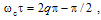 , where q is an integer. Equation (8) shows that at resonance, the value of the output intensity
  becomes a minimum. The additional condition required to make
  to become zero at resonance can be shown as:
 we have
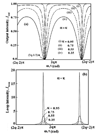
  . Figure 2 shows the theoretical output and loop intensities of the CCORR as a function of
  for different values of
  .We note that for all values of
  , the output response dips to zero, and loop intensity peaks to a maximum value, indicating the resonance condition. As the value of
  decreases, the sharpness of the resonance response decreases as well.When
  , it can be shown that at resonance when
  , the maximum developed loop intensity
  is:
is: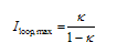
 . A reduction of the value of
  from 0.95 to 0.75 causes the maximum loop intensity to decrease from 19 to 3. We note that in Fig. 2(b) the resonance response is not sharp when the value of
  is small.
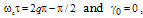 the normalized output intensity can be shown by:
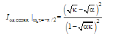
 and
and 
 can be derived as:
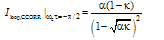
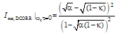
 at
at  as a function of
  and α. The normalized output intensity is equal to
  for
for  , is zero when
  , and is unity at
  . According to Eq. (14), under the resonance condition, if
  , the theoretical value of
  tends to be large when κ tends to unity. But when
  , the power coupling in the coupler of the CCORR will be 100 percent, resulting in a zero loop intensity.
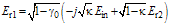

 from Eq. (18) can be shown as:
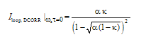
 and
and  . The additional condition for the output intensity
  to become zero at resonance is given by:
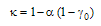
 will be:
 of the DCORR as a function of
  and Fig. 4 illustrates the normalized loop intensity
  , assuming
  and
and  .
. whereas in the latter it occurs at
 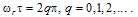 . The major difference between two configurations lies in the value of
  , where in the DCORR, when value of
  is lower, the finesse of the resonator will be higher, while in case of the CCORR is reverse. Moreover, we note that at resonance conditions, at whatsoever value it maybe, the loop intensity in CCORR is nearly twice the value in the DCORR.For practical reasons, the CCORR configuration in Fig. 1(a) is usually employed, since such a configuration can be fabricated by using a single length of an optical fiber without a need of any splice joint. To obtain high finesse or to make α as large as possible, it is desirable to avoid a splice joint in the loop fiber. To fabricate the configuration of DCORR in Fig. 1(b), two separate lengths of optical fibers would be needed to realize the coupler and a splice joint would be required to make the loop.
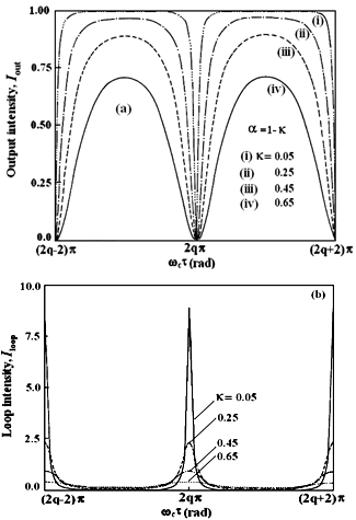
 and
and 
 , and compared the results with the previously reported ORR configuration.The analyses have shown that the characteristic behaviors of both the configurations are the same. The main difference between two ORRs is due to the value of power coupling coefficient of the couplers used for their configurations. Another major point is that in CCORR configuration the loop power is nearly double of the value in the DCORR case. The analytical results given in this article can be useful for selection of ORR configuration for particular applications, such as high power generation and investigation of nonlinear phenomena.