-
Paper Information
- Paper Submission
-
Journal Information
- About This Journal
- Editorial Board
- Current Issue
- Archive
- Author Guidelines
- Contact Us
International Journal of Optics and Applications
p-ISSN: 2168-5053 e-ISSN: 2168-5061
2012; 2(2): 6-14
doi:10.5923/j.optics.20120202.02
Effects of Hydrostatic Pressure and Thermal Loading on Optical Fibers Coated with Multilayer Segmented Young’s Modulus Materials
1Optical Communication Group, Iran Telecom Research Center, Tehran, Iran
2Electrical Eng. Dept., Ghiasodin Jamshid Kashani Institute of Higher Edu., Abyek, Qazvin, Iran
Correspondence to: Faramarz E. Seraji, Optical Communication Group, Iran Telecom Research Center, Tehran, Iran.
| Email: |  |
Copyright © 2012 Scientific & Academic Publishing. All Rights Reserved.
In this paper, we have reported two-layer coated fiber with tightly jacketed layer of segmented Young’s modulus (YM) material. In our proposed model, we have considered six layers out of which first two layers are assumed of soft material and the next four layers consist of hard materials. In our analysis we have dealt with the effects of hydrostatic pressure and thermal loading on microbending loss and refractive index changes of the fiber in radial, tangential, and axial directions. The microbending loss due to lateral pressure was calculated by taking layer thicknesses, Young’s modulus, Poisson’s ratio, hydrostatic pressure, and thermal loading as parameters of different cases of calculations. The results have shown that increase in soft layers’ thickness reduces the fiber losses. The inclusion of successive hard-material layers causes an increase in the fiber loss. Increase of soft material layers’ thickness has caused increase in loss and reaches a minimum value at a particular thickness of the corresponding layer. As a result, it is shown that increase of the YM of soft layers increases the fiber microbending loss while the increase in case of hard layers would decrease the fiber bending loss. In addition, higher Poisson’s ratio of soft layers would increase the loss but its higher values for hard layers would decrease the loss values.
Keywords: Hydrostatic Pressure, Thermal Loading, Optical Fibers, Multilayer Segmented, Young’s Modulus
Cite this paper: Faramarz E. Seraji, Effects of Hydrostatic Pressure and Thermal Loading on Optical Fibers Coated with Multilayer Segmented Young’s Modulus Materials, International Journal of Optics and Applications, Vol. 2 No. 2, 2012, pp. 6-14. doi: 10.5923/j.optics.20120202.02.
Article Outline
1. Introduction
- Due to rapid growth of bandwidth and demands of transmission distance at world wide level, a strong desire is developed in research workers and giant optical fiber producers to improve the fiber properties to meet the challenge of the bandwidth-distance product so as to meet the undergoing next generation networks requirements[1].To meet the demand of such needs in different applications of fiber communication system, wavelength division multiplexing (WDM) and dense wavelength division multiplexing (DWDM) systems have been designed and implemented. These systems are designed in such a way to employ newly designed optical fiber such as large effective area fiber for better performance and reliabilities[1]. To increase the channel bite rate in a long haul transmission, in recent years, optical fiber such as large effective area fiber and non-zero dispersion shifted fibers have been designed to be employed in high-capacity WDM/DWDM transmission system, operating in longer wavelength from 1530 to 1565 nm[2-8].Mechanical pressures and thermal stresses are two main factors that can leave undesired effects on optical fibers resulting in increase of loss in transmission systems. To avoid such adverse conditions, communication fibers in the time of production, are usually coated by polymeric materials with two to three layers of which the inner layer is a soft material to prevent the microbending of the fiber structure, and the outer one that is hard enough to protect the fiber against severe environmental factors[9]. Both the layers in turns have common role of minimizing transmission losses of fibers which mostly comprises of macro- and microbending losses[10-12]. Another major role of the fiber outer layer is to increase the mechanical strength of the produced fiber for which extensive work have been reported (see e.g.,[13-17]).In recent publications, the microbending loss and the radial, axial, and tangential stresses due to hydrostatic pressure and thermal loading have been dealt with and determined for single[18,19] and two-layers polymer coated optical fibers[19-23]. Recently, a Patent on multi-layered coating system is reported where by using three-coating and fou-coating system afforded improvement in microbend performance[24]. Similar reports have been published for calculating microbending loss by considering a third tight layer jacketed over two-layer coated fibers[25, 26]. In the report[25] it is concluded that for minimizing the microbending loss due to lateral pressure, the Poisson’s ratio of primary and secondary coating, and the Young’s modulus of the jacket material should be increased and that of the primary coating should be decreased. A similar conclusion is drawn in case of two-layer coated optical fibers[20]. Recently, we reported an analysis of microbending loss, refractive index change, and stress components of a double-coated optical fiber by considering the effect of temperature rise and hydrostatic pressure on coating parameters such as Young’s modulus and the Poisson ratio[27]. In a more recent report, the transient microbending loss and refractive index changes in a single-coated[28] and tightly jacketed double-coated[29] optical fibers subjected to thermal loading are investigated. In all aforesaid reports, for improving fiber performance, the increase or decrease in the parameters’ values is considered to be step-wise. In this paper, we have extended the analysis of our recent report[30] where a two-layer coated fiber tightly jacketed with a layer of segmented Young’s modulus material was proposed. In our model, within the tight jacket, we considered six layers out of which first two layers are of soft materials and the next four layers consist of hard materials. To comply with the segmented change of the Young’s modulus in the scale of GPa, the successive layers differ slightly in terms of hardness.For our model, we determine the pressure exerted in each layers and then calculate the effects of hydrostatic pressure and thermal variations on microbending losses in fiber. Finally, we determine the tangential, radial, and axial stresses and refractive index changes of different layers.
2. Lateral Pressure and Displacement of Layers
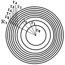 | Figure 1. The proposed two-layer coated fiber jacketed with segmented Young’s modulus materials |
 having three coating layers of thickness
  ,
,  , and
, and  , respectively, where in layer
  , we assume further six sub-layers with respective thicknesses of
  ,
,  ,
,  ,
,  ,
,  , and
, and  , as shown in Fig. 1. Each of these sub-layers is made of different polymeric materials. Let us show the mechanical parameters of these layers with usual notations
  ,
, , and
, and  as Young’s modulus, Poisson’s ratio, and thermal expansion coefficient, respectively. The indices
  in
in  indicate the corresponding fiber or the layer sequences.In our calculations, we assume that first two coating layers are soft and hard coating used usually in communication optical fibers and the next third and fourth layers are of soft materials, and the Young’s modulus of the fourth layer is higher than that of third layer. It is also assumed that the materials of fifth to eighth layers as outer coating are of hard type, which is assumed for better mechanical protection of the fiber.Now we consider the effects of two factors, i.e., hydrostatic pressure
  and the thermal loading
  (thermal drop greater than zero), affecting the refractive index and creating losses in the fiber. First, if we consider only the presence of thermal loading on the fiber and assume
  , it results in development of pressure starting from outermost to innermost layers, which is due to mechanical properties such as Young’s modulus and thermal expansion coefficient of the layers[20]. It is further assumed that the fiber and the coating layers are cylindrically symmetric. Irrespective of visco-elastic theory and by considering the theory of elasticity, the strain-stress relationship can be expressed as[Ref. 31: p. 408, eq. 239b]:
 | (1) |
 is the layer displacement at radius
  from the fiber axis. In one particular layer, the displacements are different at different radii. The ratio
  denotes the tangential strain, and
  and
and  indicate the radial and tangential stresses, respectively. In our analyses, in each layer, we have taken the values of
  and
and  constant to comply with the step change as it is proposed. To determine the layers’ displacements, we are to define the values of
  and
and  .
.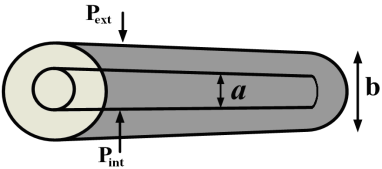 | Figure 2. Cylindrical structure with internal and external diameters of  and and  respectively, under a thermal variation of respectively, under a thermal variation of  and internal and external pressure of and internal and external pressure of  and and  |
 and external radius of
  as shown in Fig 2, is exposed to internal and external pressures of
  and
and  , according to Lamé formula we can write[Ref .31: p. 59, eq. 45]:
 | (2) |
 | (3) |
 and the temperature variation (
 ) and pressure can be expressed as:
 | (4) |
 is the ratio of radii of the coating layers. The radial displacements of the layers at their interfaces are thus given by:
 | (5) |
 | (6) |
 is the (i+1)th layer displacement at ith interface position and
  is the ith displacement at (i+1)th layer interface, where
  is taken from zero to
  , where
  is the maximum value of
  equal to total number of layers minus one.In (5) and (6),
  ,
,  , and
, and  are thermal expansion coefficient, Young’s modulus, and Poisson ratio of the ith layer and,
  , and
, and  are the corresponding parameters at (i+1)th layer. The lateral pressure
  is exerting between (i-1)th and ith for calculating
  and
and  , between ith and (i+1)th, and between (i+1)th and (i+2)th, respectively. It should be noted that for the case of
  , when
  takes the value of
  , the resulting lateral pressure would be the hydrostatic pressure exerted externally on the fiber and
  . As an example, at interface of the fiber with first layer
  , since internal pressure does not exit and core and cladding are assumed to have the same Young’s modulus and nearly equal to thermal expansion coefficients, thus
  and
and  and the radial displacement of the first layer
  is then given as:
 | (7) |
 | (8) |
 ,
,  , and
, and  denote the fiber parameters and
  ,
,  , and
, and  are the corresponding parameters for the first layer. The lateral pressure
  is exerted between the fiber surface and the first layer,
  is between first layer and second one, and
  . In a general form,
  and
and  continue till the desired layer, when we set
  .At all the layers interfaces, the displacements are equal as cylindrical symmetry is assumed for the fiber and the layers, i.e., by equating
  and
and  at each layer interface. The lateral pressure exerted on the fiber and different layers due to thermal change and hydrostatic pressure can be determined by[30]
 | (9) |
 | (10) |
 and
and  are defined as:
 | (11) |
 | (12) |
 | (13) |
 | (14) |
 ,
,  ,
,  , and
, and  are expressed as:
  | (15) |
 | (16) |
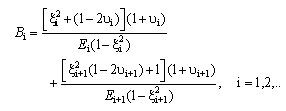 | (17) |
 | (18) |
 | (19) |
 | (20) |
3. Microbending Loss
- Basically microbendings are created in optical fibers during fabrication and installation processes or could be due to hydrostatic pressure and temperature gradient between fiber and the coating materials which have different thermal expansion coefficients that result in shrinkage of the coating on fiber itself and causing microbends along the fiber length[20]. To minimize these external effects, during cabling process, fibers are wrapped with different jackets in several layers[32].The experimental results show that the microbending loss is directly proportional to lateral pressure and is expressed as[18]:
 | (21) |
 is a constant equal to 0.0029 (dB/km)/MPa and
  is the exerting pressure between layer
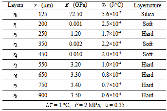
  and the fiber itself. The fiber and coating parameters’ values used in our calculation are given in Table 1.
|
4. Effect of Coating Layer Thickness
- The fiber loss curves due to the effects of different coating layers thickness (from
 to
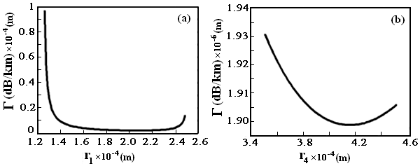
to  ) on fiber loss are illustrated in Fig. 3. An increase of thickness in layers 1st to 3rd and 8th layer causes a reduction in the fiber loss but on the contrary, in layers from 4th to 7th, an increase in loss is observed. It indicates that the presence of few successive hard layers without soft layers in between them causes an increase in fiber loss. It is specifically noted that increase in soft third layer results in loss reduction.
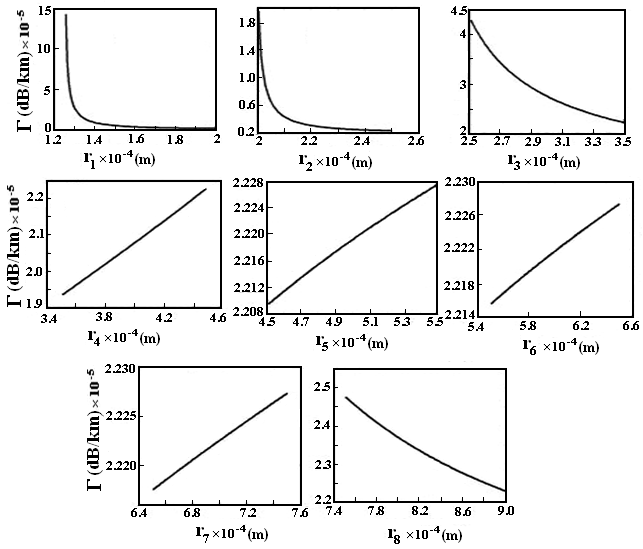 | Figure 3. The effect of coating layers thickness on the loss of fiber with segmented Young’s modulus multilayer-coating |
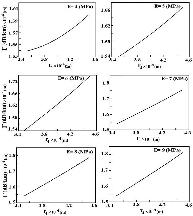 | Figure 5. Variation of loss in terms of 4th layer thickness with Young’s modulus as a parameter |
5. Effect of Young’s Modulus and Poisson’s Ratio
- The effect of Young’s modulus of the multilayer coating materials on fiber loss are shown in Fig. 6, where in each curve two successive layers are considered. It is shown that higher values of Young’s moduli in the first, third and the fourth layers have increasing effects on fiber loss whereas for higher values in layers from fifth to eighth, the loss reduces. We also note that increase of Young’s modulus of 2nd layer would have no effect on fiber loss. On other words, harder the outer layers more will be the fiber resistance to hydrostatic pressures and thermal changes.
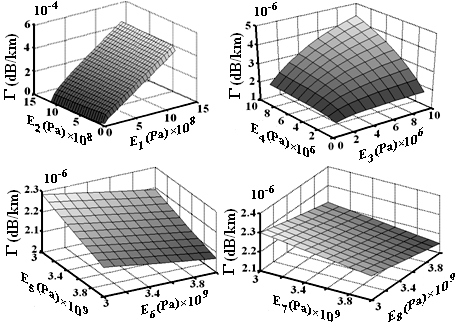 | Figure 6. The effect of Young’s modulus on loss of the fiber |
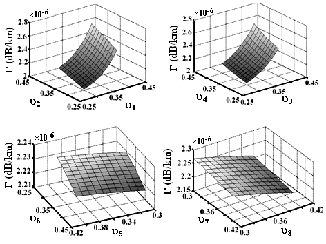 | Figure 7. The effect of Poisson’s ratio on loss of the fiber |
 and hydrostatic pressure
  , as depicted in Fig. 8. It is shown that changes in temperature gradient and in hydrostatic pressure would cause a change in the lateral pressure, which results in corresponding linear increase in fiber loss.
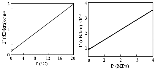 | Figure 8. Effect of hydrostatic pressure and thermal loading on the fiber loss |
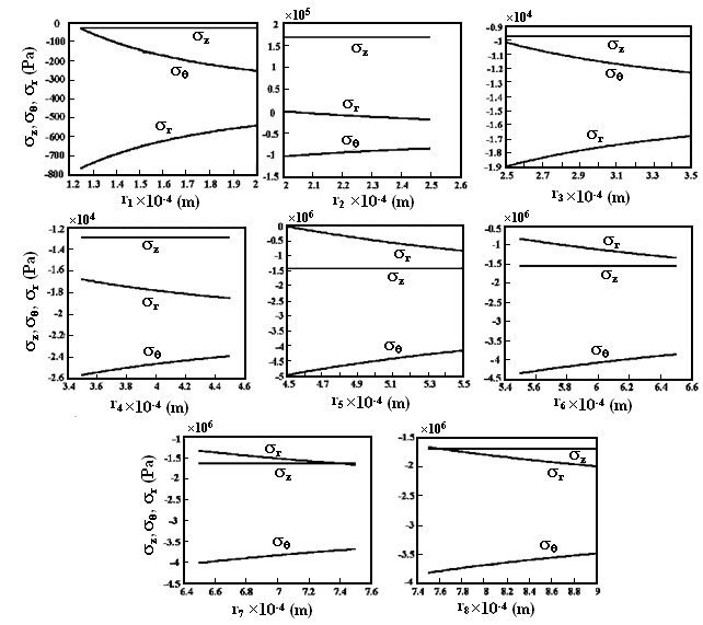 | Figure 9. Radial, tangential, and axial stresses in multilayer-coated fiber with segmented Young’s modulus materials |
6. Radial, Tangential, and Axial Stresses on Coating Layers
- The lateral pressures, which are exerted on multilayers interfaces, develop some stresses within the corresponding layers. Radial and tangential stresses are defined by (2) and (3) and the axial stress is expressed as[31]:
 | (22) |
 | (23) |
 | (24) |
 and the tangential stress
  at ith layer on the fiber are obtained by using
  ,
,  ,
,  , and
, and  in (1) and (2), as follows:
 | (25) |
 | (26) |
 | (27) |
7. Refractive Index Variations in Radial, Tangential, and Axial Directions
- The lateral pressure exerted to fiber by exerted external hydrostatic pressure, would reduce due to presence of different coating layers, but still there would be some effects on the fiber. The exertion of lateral pressure at interface of 1st layer and the fiber itself causes geometrical distortion of fiber structure, resulting fiber thickness changes along radial, axial, and tangential directions and hence change in symmetry of fiber cross-section[33]. The change in refractive index of the fiber would affect mostly on the transmission characteristics of the fiber.The relationship between the refractive index variations along direction with different radial, tangential, and axial stresses are expressed by[34]:
 | (28) |
 | (29) |
 | (30) |
 denotes the refractive index of the fiber before exertion of pressure and thermal change and
  ,
,  , and
, and  are the indices along three directions.
  and
and  are stress-optical constants for ordinary and extraordinary rays equal to 4.2×10⁻⁶/MPa and 6.5×10⁻⁷/MPa, respectively[35]. The parameter values of the designed fiber have been given in Table 1.In Fig.10, the effects of coating layers thickness on fiber refractive index along radial, tangential, and axial directions are plotted. The parameters variations in first and second layers are high for
  <1.410-4 m and
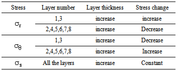
  <2.110-4 m as compared with other layers. This difference could be due to closeness of the the first two layers to the fiber itself.Figs.11 and 12 show the effects of Young’s moduli and Poisson’s ratios of coating layers on refractive index change along radial, tangential, and axial directions, respectively. The effects of hydrostatic pressure and temperature on refractive indices along the radial, tangential, and axial directions are illustrated in Fig.13. Increase of hydrostatic pressure causes refractive index variations increase linearly along the three directions almost with the same slopes. The variation of temperature would cause refractive index changes in all directions. In both the cases, the radial and tangential refractive index changes coincide on each other. All the obtained results of the analyses are summarized in Tables 2 to 4, respectively.
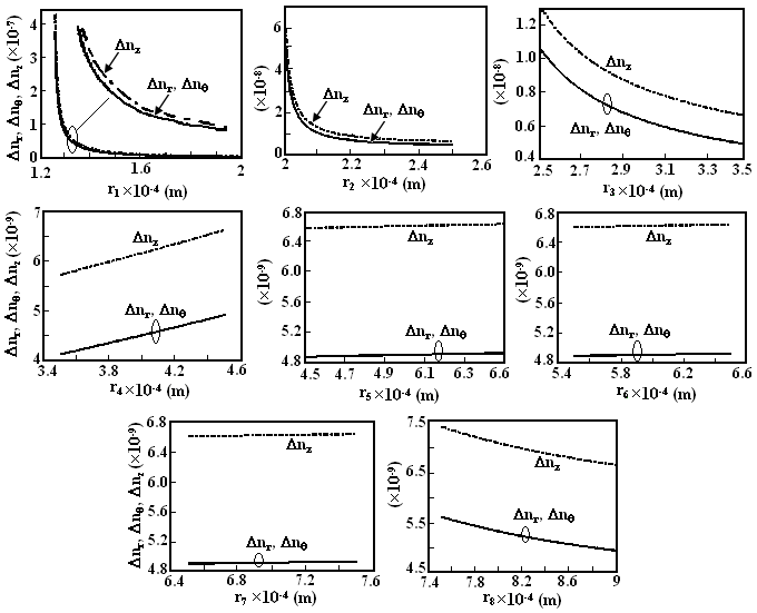 | Figure 10. Effects of different layers thicknesses on radial, tangential, and axial refractive indices of the fiber under hydrostatic pressure and thermal loading |
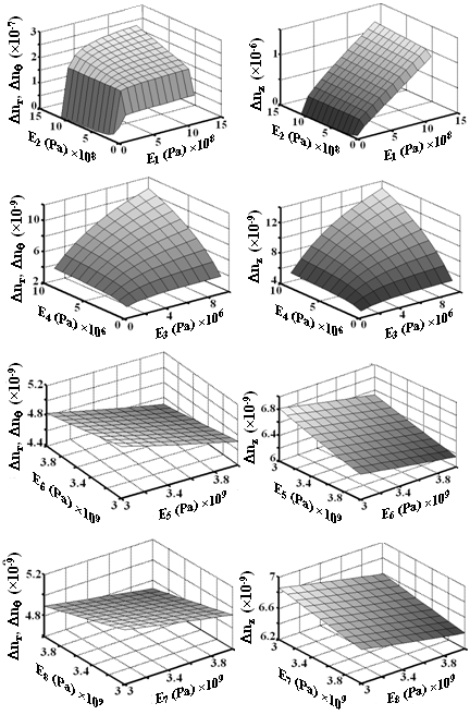 | Figure 11. The effects of Young’s moduli of different layers on radial, tangential, and axial refractive indices of the fiber under hydrostatic pressure and thermal loading |
8. Discussion and Conclusions
- We have presented an alternate version of two-layer coated fiber with tightly jacketed layer of segmented Young’s modulus material. We have considered six layers out of which first two layers are of soft material and the next four layers consist of hard materials. The effects of hydrostatic pressure and thermal loading on microbending loss are analyzed. The lateral pressure and displacement of layers under environmental conditions were determined and have shown that the lateral pressure exerted in different layers is directly proportional to hydrostatic pressure and thermal loading. On the other hand, it is shown that the lateral pressure is related effectively to layers thickness, Young’s modulus, Poisson’s ratio, and thermal expansion coefficients of the polymeric layers.By taking the lateral pressure exerted on fiber into account, the microbending loss developed in the fiber was calculated by considering layer thicknesses, Young’s modulus, Poisson’s ratio, hydrostatic pressure, and thermal loading as parameters of different cases of calculations. The results in different cases have shown that increase in thickness of soft layers 1st, 2nd, 3rd, and 8th reduces the fiber losses. The inclusion of successive layers of soft material (4th layer) and hard materials (5th, 6th, and 7th layers) causes an increase in the fiber loss. Increase of soft material layers’ thickness has caused increase in loss and reaches a minimum value at a particular thickness of the corresponding layer. If two soft layers with nearly same Young’s modulus get adjacent to each other, the minimum loss would transfer to next higher soft layer. But if the next soft layer’s Young’s modulus is a few order of magnitude higher than the previous soft layer, comparatively acts as a hard layer and causes loss increase in the fiber with an increase in its thickness. Increase of Young’s moduli of 1st, 3rd and 4th soft layers would increase the fiber loss but in hard layers from 5th to 8th the loss would decrease. It is shown that higher Poisson’s ratio of soft layers would worsen the loss but in hard layers, its higher value acts oppositely and lowers the loss value.By calculations of orthogonal stresses, it is shown that the axial stress in all the layers remains almost constant. The radial stress in 1st and 3rd soft layers increases with an increase of layer thickness and increase of hard layers and 4th layer thicknesses causes a decrease in radial stress. The tangential stress in soft layers decreases with an increase of layer thickness and increases with increase of hard layer and 4th layer thicknesses. It is shown that, the radial, tangential and axial stresses at interfaces of 5th and 6th, 6th and 7th, 7th and 8th layers are continuous.It is shown that increase of 1st, 2nd, 3rd, and 8th layer thickness would result in reduction of refractive index change. Increase of thickness of 4th layer is accompanied with increase of refractive index change, but the 5th, 6th, and 7th layer thicknesses would cause a slight increase in the refractive index change of the fiber.It is further shown that the refractive index of the fiber increases in three orthogonal directions, when the Young’s moduli of 1st to 4th layer increase, but in case of 5th to 8th layers, the refractive index changes would decrease. Similar condition holds good for the case of Poisson’s ratio, except in layer 5th, instead of reduction there will be an increase in refractive index changes in three dimensions.The presented results, besides in communication fibers, could also be utilized in design of fiber sensors.
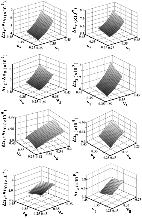 | Figure 12. The effects of Poisson’s ratios of different layers on radial, tangential, and axial refractive indices of the fiber under hydrostatic pressure and thermal loading |
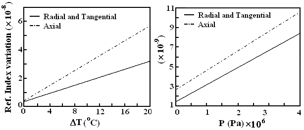 | Figure 13. Effects of hydrostatic pressure and thermal loading on radial, tangential, and axial refractive indices of the fiber |
|
|
|
 Abstract
 Reference
 Full-Text PDF
 Full-text HTML