-
Paper Information
- Next Paper
- Previous Paper
- Paper Submission
-
Journal Information
- About This Journal
- Editorial Board
- Current Issue
- Archive
- Author Guidelines
- Contact Us
International Journal of Optics and Applications
p-ISSN: 2168-5053 e-ISSN: 2168-5061
2012; 2(1): 17-21
doi: 10.5923/j.optics.20120201.02
Analysis of Fresnel Loss at Splice Joint Between Single-Mode Fiber and Photonic Crystal Fiber
 Abstract
 Reference
 Full-Text PDF
 Full-Text HTML
Samira Farsinezhad 1, Faramarz E. Seraji 2
1Excitonics and Nanostructures Laboratory, University of Alberta, Canada
2Optical Communication Group, Iran Telecom Research Center, Tehran, Iran
Correspondence to: Faramarz E. Seraji , Optical Communication Group, Iran Telecom Research Center, Tehran, Iran.
| Email: |  |
Copyright © 2012 Scientific & Academic Publishing. All Rights Reserved.
An analysis of Fresnel loss at splice joint of single-mode fiber (SMF) and two types of photonic crystal fibers (PCFs) using improved full-vectorial effective index methods is presented. The effects of air-hole size (d), air-hole spacing  , longitudinal misalignment between spliced SMFs and PCFs on the Fresnel loss is analyzed and is shown that when
  and the dopant concentration in the core of PCFs increases or the ratio
  decreases, the Fresnel loss will decrease. The results of the analysis may be used by network designers to predict over all loss when employing PCF-based devices in optical fiber networks.
Keywords: Fresnel loss, Single-mode fiber, Photonic crystal fiber
Cite this paper: Samira Farsinezhad , Faramarz E. Seraji , "Analysis of Fresnel Loss at Splice Joint Between Single-Mode Fiber and Photonic Crystal Fiber", International Journal of Optics and Applications, Vol. 2 No. 1, 2012, pp. 17-21. doi: 10.5923/j.optics.20120201.02.
Article Outline
1. Introduction
- In recent years, due to growth of optical communication networks, the splice joint between single-mode fibers (SMFs) as a transmission medium, and photonic crystal fiber (PCF) based devices has attracted more research work. One of the issues at the splice joint of SMFs and PCF-based devices worthy to attend is the reflection of light ray called as Fresnel reflection which is due to a possible change of refractive index at the splice point[1]. This phenomenon causes development of extra loss at the joint.In the early research works, losses due to Fresnel reflection between SMFs were well reported[2-4]. The recent reports focused on the loss at the splice joints between SMF and PCF, where the attempts were made to optimize the spliced PCF parameters such as air-hole spacing
 and air-filling factor
  for reduction of the loss resulting from coupling mechanism between them[5-8].In the reported investigations[5, 8], the core refractive index of the spliced fibers was assumed to be equal and there was no indication of the influence of effective refractive index of PCFs on the loss due to Fresnel reflection. By creating a critical angle of 8 degrees at the end faces of spliced SMFs and hollow core PCFs, the Fresnel reflection may be avoided [1].In connecting the PCF-based devices to SMFs, we should consider the influences of
  on the Fresnel loss at the joint [9]. The presence of air-holes in the cladding region of the PCFs causes change in behavior of the joint which can be studied using effective refractive indices of the spliced fibers[5, 6]. In our previous reports, a mechanism was proposed using improved fully vectorial effective index method (IVEIM) to optimize splice joint of PCFs and SMFs[10]. In this paper, for the first time to our knowledge, we report an analysis of Fresnel loss at the splice joint of SMF and solid core PCFs.In the analysis of the present paper, by using IVEIM[11, 12], we will consider the splice joints between single-mode fiber and two structurally different PCFs, i.e., conventional PCF (CPCF) and raised-core PCF (RCPCF)[13] to investigate the influences of PCFs parameters
  on reduction of Fresnel loss at the splice joint.
2. Formulation of Fresnel loss for Splice joint
- To calculate the Fresnel loss, Fig. 1 is considered for a splice of the fibers where their end facets, at a distance
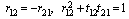
 apart, are assumed parallel to each other. The incident rays are assumed perpendicular to the end facets. The ray transmission from fiber 1 to fiber 2 experiences reflections twice, one at the interface between end facet of fiber 1 and the air gap, and the other between the air gap and the entering facet of fiber 2.In general, in Fig. 1(a), the two co-directional rays (one of them is shown), normal to the plane wave front in fiber 1 after crossing medium n2, strike the front end of fiber 2 and then are transmitted partially into medium n3. For the net amplitude reflection coefficient r, the Fresnel coefficients for each boundary are used with a phase difference of β. We note that the Fresnel coefficients are different for s- and p-polarization.Therefore, we can write the following expressions for r[14]:
 (1)With similar derivation, we can write the net amplitude transmitted into fiber 2 as:
 | (2) |
 is the phase difference, where
  and q=0 in a nonconducting medium for all angles of incidence,
  is the angular frequency of light, and c is the velocity of light in a vacuum.
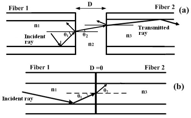 | Figure 1. Demonstration of Fresnel loss at the splice joint of any two fibers (a) D≠0 and (b). D=0 |
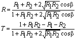
 are used. So based on Fresnel coefficient, we can write the intensity reflectance r as:
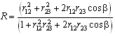 | (3) |
 | (4) |
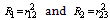 indicate the reflectance between fiber 1 and the air-gap, and between the air-gap and fiber 2, respectively[14]. With reference to Fig. 1(a), at normal incidence for D≠0, the reflectance for both s- and p-polarization and the phase difference β can be shown as[15]:
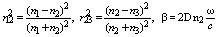 | (5) |
 | (6) |
 | (7) |
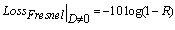
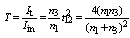
 are the transmitted and incident intensities, respectively. Then the loss due to the Fresnel reflections can be derived as[2, 15]:
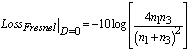 | (8) |
 . Since for D≠0, n2 can be the refractive index of the air-gap (n2=1), the condition for zero Fresnel loss will be
  .With the above discussion, let us now consider the splice between an SMF and a PCF. To be more specific on the light propagation through fibers at splice joint, we can presume that the light sees an effective refractive index rather mere core refractive index, which agrees usually with a practical condition. Under this situation, the influences of PCF parameters
  can bring us the structural effects on the Fresnel loss at the splice point of the SMF and the PCF.Now, to start with our study, we assume a perfect splice between the SMF (fiber 1) and the PCF (fiber 2), i.e., a splice with no longitudinal displacement D=0. Therefore, Eq. (8) reduces to:
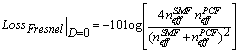 | (9) |
 are the effective refractive indices of the SMF and the PCF, respectively.
3. Numerical Results
- We consider splicing of SMF to a CPCF and a RCPCF in a separate calculation. To determine optimal values of refractive indices of silica cores of the spliced fibers,
 of the SMF,
  of the CPCF, and
  of the RCPCF, we used Sellemier equation and numerical IVEIM method, respectively, which are generally utilized[10, 11, 16,17].The numerical results for
  are illustrated in Fig. 2 in terms of
  for different values of
  . We note that the effective refractive index as a function of
  , experiences higher variations as
  increases. The range of this variation is less in case of the RCPCF.For the splice joints of the SMF to the CPCF and the RCPCF [10, 13], the Fresnel losses, based on Eq. (9), in terms of
  for different values of
  are illustrated in Fig. 3 using IVEIM method. When
  increases, the Fresnel loss will decrease whereas increase of
  would cause an increase in the Fresnel loss for a given
  , as shown in Fig. 3.For higher values of
  , the slopes of the curves decrease, showing a lesser influence of the ratio
  . It is noted that with the same values of
  in Fig. 3(a), the replacement of CPCF with RCPCF in a splice with SMF has caused reductions of the Fresnel loss. As
  increases, this effect is more prominent, as indicated in Fig. 3(b). In fact, at higher values of
  , the Fresnel loss changes linearly and its dependency on
  will be weak. For instance, when
  and
and  , we observe more than 50% reduction of the Fresnel loss when using RCPCF[18].
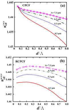 | Figure 2. Calculations of the effective refractive index (a)  and (b) and (b)  by using IVEIM at 1.55 by using IVEIM at 1.55  . . |
 and
and  for different values of
  at 1.55
  . For all values of
  and
and  , all the minima at D=0.39, 1.16, 1.94 μm remain almost constant at low level 0.001 dB, as shown in Fig. 4(a). The maxima of the Fresnel losses change slightly for higher values of
  . When d increases, the maximum Fresnel loss will go higher, as shown in Figs. 4(b) and 4(c). If
  is assumed constant, the Fresnel loss maintains sinusoidal changes with almost zero values at some longitudinal displacements points that do not alter with parameter changes, as these points depend on the ratio
  .In fact, for lower values of
  , when there is longitudinal displacement at the splice joint, the Fresnel loss dose not depend on structural parameters of the PCFs. It is reminded the presence of longitudinal displacement at the splice joints of two fibers causes two reflections.One of the approaches to nullify the Fresnel loss at the splice joint is to maintain the following condition:
 | (10) |
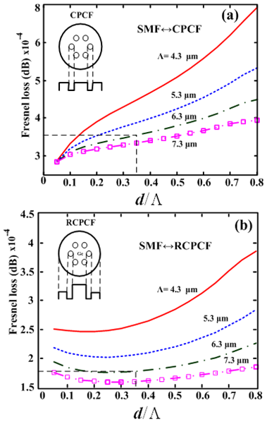 | Figure 3. Calculations of Fresnel losses at perfect splice joints between SMF and (a) a CPCF and (b) an RCPCF, showing the influences of  and and  |
 ,
,  , and implicitly depends on the wavelength.In all the calculations, it is assumed the light strikes the end facets of the fibers at right angle, whereas in practice it is not so. Now, for practical case, we consider an incident angle
  for the input ray for s- and p-polarization (See Fig. 1).For a non-magnetic medium, the reflection coefficients of s –polarization (Rs) and p-polarization (Rp) with a non-zero incidence angle
  and refracted angle
  for D=0 are expressed in general form as[14]:
 | (11) |
 | (12) |
 in Eqs. (11) and (12), the effect of incident angle on Rs and Rp is determined and plotted in Fig. 5 by considering
 µm, and
  It indicates that when the ray is incident at the interface between two spliced fibers with an angle of about 45 deg, the Fresnel loss will be zero. This angle is the well-known Brewster angle at which the reflectance for
  -polarization is zero. Therefore, the validity of considering zero incident angle for small Fresnel loss may be extended to even higher incident angles.
 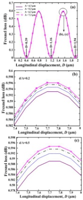 | Figure 4. Variations of the Fresnel loss as a function of longitudinal displacements using IVEIM at 1.55  |
 used for our calculations, we noted that there were almost no changes in the variations of Rs and Rp. This also implies that our assumption of
  being zero is justified.
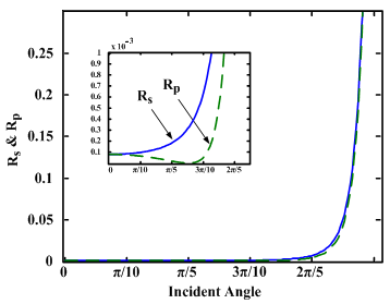 | Figure 5. Reflection coefficients of s- and p-polarization as functions of the incident angle for SMF and PCF splice joint.   =0.345. λ=1.550 =0.345. λ=1.550  n1=1.4701, n3=1.465. n1=1.4701, n3=1.465. |
 and
and  for the PCF-based devices lie in the single-mode region, which are the values resulting in a low Fresnel loss with a reasonable approximation based on present results in Fig. 3 [10, 17, 13].
4. Conclusions
- We presented an analysis of Fresnel loss at splice joint of SMFs and two different types of PCFs (CPCF and RCPCF) by using improved fully vectorial effective index methods. By formulating the dependency of the Fresnel loss on the PCF parameters
 and
and  and including the influences of effective refractive index of the fibers at the splice joint of SMFs and PCFs, the parameters ranges are determined for minimum Fresnel losses.The analysis has shown that when the air-hole radius of spliced PCFs increases or when the RCPCF is used, there will not be a suitable method. Instead, IVEIM method will present better results.It is shown that by increasing the effective index of the core, an increase of
  and a decrease of
  would reduce the Fresnel loss by more than 50%. Our analysis also shows that when using RCPCF, the design and fabrication become more flexible with respect to
  and
and  . By considering a special case of
 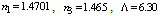 µm, and
  , at an incident angle of about 45 deg. the Fresnel loss will be zero. In addition, it is shown that the effect of incident angle at the splice joint on the Fresnel loss is not considerable.To optimize the Fresnel loss at the splice joint of SMFs and PCFs, three approaches are proposed: 1) use of a material with a known refractive index at the splice joint, 2) control via longitudinal misalignment at the splice joint, and 3) control via PCF parameters
  and
and  .With reference to our recent results[10, 17, 13], we note that the optimized values of
  and
and  for the PCF lie in the single-mode region, which are the values resulting a low Fresnel loss with a reasonable approximation based on present results.
 doi:10.1016/j.ijleo.2010.02.004, (In press).