Nanoscience and Nanotechnology

p-ISSN: 2163-257X    e-ISSN: 2163-2588

2012;  2(3): 22-48

doi: 10.5923/j.nn.20120203.01

Mechanical Milling: a Top Down Approach for the Synthesis of Nanomaterials and Nanocomposites

Thakur Prasad Yadav1, 2, Ram Manohar Yadav3, Dinesh Pratap Singh4

1Department of Physics, The University of Liverpool, Liverpool, L69 3BX, UK

2Department of Physics, Banaras Hindu University, Varanasi-221005, India

3Department of Physics, VSSD College, Kanpur, India-208002

4Avenida Ecuador 3493, Estación Central, Departamento de Física, Universidad de Santiago deChile Santiago-9170124, Chile

Correspondence to: Thakur  Prasad Yadav, Department of Physics, The University of Liverpool, Liverpool, L69 3BX, UK.

Email:

Copyright © 2012 Scientific & Academic Publishing. All Rights Reserved.

Abstract

Synthesis of nanomaterials by a simple, low cost and in high yield has been a great challenge since the very early development of nanoscience. Various bottom and top down approaches have been developed so far, for the commercial production of nanomaterials. Among all top down approaches, high energy ball milling, has been widely exploited for the synthesis of various nanomaterials, nanograins, nanoalloy, nanocomposites and nano -quasicrystalline materials. Mechanical alloying techniques have been utilized to produce amorphous and nanocrystalline alloys as well as metal/non-metal nanocomposite materials by milling and post annealing, of elemental or compound powders in an inert atmosphere. Mechanical alloying is a non-equilibrium processing technique in which different elemental powders are milled in an inert atmosphere to create one mixed powder with the same composition as the constituents. In high-energy ball milling, plastic deformation, cold-welding and fracture are predominant factors, in which the deformation leads to a change in particle shape, cold-welding leads to an increase in particle size and fracture leads to decrease in particle size resulting in the formation of fine dispersed alloying particles in the grain-refined soft matrix. By utilizing mechanical milling various kind of aluminium/ nickel/ magnesium/ copper based nanoalloys, wear resistant spray coatings, oxide and carbide strengthened aluminium alloys, and many other nanocomposites have been synthesized in very high yield. The mechanical milling has been utilized for the synthesis of nanomaterials either by milling and post annealing or by mechanical activation and then applying some other process on these activated materials. This review is a systematic view of the basic concept of mechanical milling, historical view and applications of mechanical milling in the synthesis of various nanomaterials, nanosomposites, nnaocarbons and nano quasicrystalline materials.

Keywords: Mechanical Milling, Nanomaterials, Nanocomposites, Nanostructure, Synthesis, Mechanical Properties, Processing-Structure-Property

1. Introduction

1.1. Mechanical Milling

In mechanical milling (MM), a suitable powder charge (typically, a blend of elemental) is placed in a high energy mill, along with a suitable milling medium. The objective of milling is to reduce the particle size and blending of particles in new phases. The different type of ball milling can be used for synthesis of nanomaterials in which balls impact upon the powder charge[1]. The balls may roll down the surface of the chamber in a series of parallel layers or they may fall freely and impact the powder and balls beneath them. For large scale production with nano size grain, mechanical millings are more economical processes[2]. The kinetics of mechanical milling or alloying depends on the energy transferred to the powder from the balls during milling[3]. The energy transfer is governed by many parameters such as the type of mill, the powder supplied to drive the milling chamber, milling speed, size and size distribution of the balls, dry or wet milling, temperature of milling and the duration of milling[4]. Since the kinetic energy of the balls is a function of their mass and velocity, dense materials (steel or tungsten carbide) are preferable to ceramic balls, and the size and size distribution should be optimized for the given mill[5]. Too dense packing of balls reduces the mean free path of the ball motion, while a dilute distribution minimizes the collision frequency[6]. The temperature during milling can depend on the kinetic energy of the ball and the material characteristics of the powder and milling media. The temperature of the powder influences the diffusivity and defect concentration in the powder influencing the phase transformations induced by milling[7]. Higher temperatures are expected to result in phases which need higher atomic mobility (intermetallics) while at lower temperatures the formation of amorphous phases is expected if the energy is sufficient[8]. Low temperature can also enhance the formation of nanocrystalline phases[9]. In addition, the high strain-rate deformation and cumulative strain accompanying during collisions of balls lead to particle fracture[10]. These competing fracture and coalescence events continue throughout processing. Indeed, a suitable balance between them is required for success with the alloying process. In most application, the balance is such that an approximate steady-state powder size distribution is obtained[11]. In this stage, the particles are often shaped like flakes, and even through a steady-state powder size are found, continued microstructural refinement occurs as a result of the repetitive fragmentation and coalescence events[12].

1.2. Synthesis of Materials by Mechanical Milling: A Historical Development

The synthesis of materials by high energy ball milling of powders was first developed by John Benjamin (1970)[13] and his co-workers at the International Nickel Company in the late 1960's. The goal of this work was the production of complex Oxide Dispersion-Strengthened (ODS) alloys for high temperature structural applications. It was found that this method, termed mechanical alloying, could successfully produce fine, uniform dispersions of oxide particles (Al2O3, Y2O3, ThO2) in nickel-base superalloys which could not be made by more conventional powder metallurgy methods. In addition, reactive alloying components such as Ti, could be incorporated from master alloy powders such that it was clear that "alloying" could occur on the atomic level during the mechanical milling process. Benjamin and his co- workers at Inca Paul D. Merica Research Laboratory also explored the synthesis of other kinds of materials, e.g. solid solution alloys and immiscible systems, and pointed out (Benjamin, 1977) that mechanical alloying (MA), in addition to synthesis of dispersion-strengthened alloys, could make metal composites, compounds, and/or new materials with unique properties[14]. However, one of the major applications of MA so far has been the production of oxide- dispersion-strengthened (ODS) materials[15].

2. Mechanical Milling: Equipment and Process Variables

The milling of materials has been a major component of the mineral, ceramic processing, and powder metallurgy industries. The objectives of mechanical milling include particle size reduction, mixing or blending, particle shape changes and synthesis of nanocomposite. The typical mill used for these purposes has been the high energy ball mill such as tumbler ball mills, vibratory mills, planetary mills, and attritor mills (Szegvari attritor) etc. A detailed description of the different mills available for MM can be found in Suryanarayana handbook [25]; however we have discussed a brief description regarding high energy ball mills.
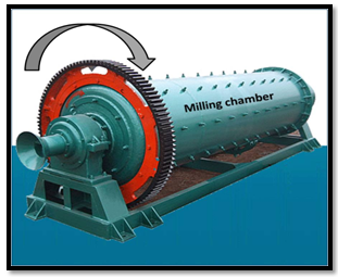
Figure 1. A rock tumbler Ball mills
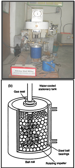
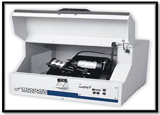
The tumbler ball mill is a cylindrical container rotated about its axis in which balls impact upon the powder charge. The balls may roll down the surface of the chamber in a series of parallel layers or they may fall freely and impact the powder and balls beneath them. The tumbler ball mill is illustrated in Fig. 1. The tumbler ball mill is operated closed to the critical speed beyond which the balls are pinned to the inner walls of the mill because of the centrifugal force dominating over centripetal force. For large scale production tumbler mills are more economical when compared to the other high energy ball mills[26]. While a number of ingenious milling devices were developed early in the century, the one high energy ball mill that has been adopted by industry was invented by Szegvari in 1922, in order to quickly attain a fine sulphur dispersion for use in vulcanization of rubber. This mill is called an attritor or attrition mill and is illustrated in Fig. 2 (a, b). Milling occurs by the stirring action of an agitator that has a vertical rotating shaft with horizontal arms (impellers). The motion causes a differential movement between the balls and the powder is achieved by the horizontal impellers attached to the vertical shaft, which is made to rotate, thus providing a much higher degree of surface contact than is achieved in tumbler ball mills. The kinetic energy imparted to the milling media in either of these kinds of mills also depends on the speed of rotation of the tumbler mill cylinder or the attritor shaft[27]. Tumbler mills may also be considered high energy mills if of sufficiently large diameter (of the order of meters) and operated just short of the critical rotational speed at which centrifugal force "pins" the balls to the mill chamber wall. For large scale production of commercial alloys, attrition mills have been largely replaced by the large tumbler ball mills. Another type of mill that has been used for pilot-size production is the vibratory tube mill. The motion of the balls and particles in a vibratory mill is complicated. The cylindrical container is vibrated and the impact forces acting on the powders are function of the rate of milling, amplitude of vibration, and mass of the milling medium. High- energy milling forces can be obtained by using high vibrational frequencies and small amplitudes of vibration. Several different kinds of laboratory-scale high energy mills have been used for research purposes. The SPEX model 8000 shaker mill has been used extensively for research on small batches of power (~10 cc), especially in the U.S.A (Fig. 3).
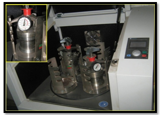
This high energy ball mill agitates the charge of powder and balls in three mutually perpendicular directions at approximately 1200 rpm. It is highly energetic compared to the attrition and vibratory mills. A given reaction can typically take place an order-of-magnitude faster in the SPEX mill than in the typical attritor or vibratory mill. Planetary ball mills have also often been used for research studies (see Fig. 4: a modified Retsch Planetary Ball Mills, PM 400[28]. Several researchers have designed their own high energy milling devices, for example, the single large steel ball (6 cm) in a tungsten carbide bottom steel vial (6.5 cm diameter) attached to a vibrating frame used by Bakker and co- workers[29]. Nanotech uniball mill has been developed by Australian Scientific Instruments, Canberra, Australia, which is widely used at present[30,31]. This mill consists of a stainless steel (inset of figure 4)) horizontal cell with hardened steel balls. The movement of the balls is confined to the vertical plane by the cell wall and is controlled by an external magnetic field whose intensity and direction can be adjusted. Depending on the position of the magnet, the mill can run in either high energy mode (impact prominent) or in low energy mode (shear prominent). Another interesting feature of this mill is the impact velocity and frequency can be independently controlled by controlling the field strength with the help of adjustable magnets.
Figure 2. (a) High energy attritor ball mill (b) Arrangement of rotating arms on a shaft in the attrition ball mill (department of Physics, BHU)
In addition to the above mills, several other mills such as a single large ball in a vibrating frame mill[32], rod mill[33], modified rod mill[34] and other specially deigned mills[35] have been used for MM. The energy of the milling media depends on the internal mechanics of the specific mill, the power supplied to drive the milling chamber, the composition, size, and size distribution of the balls. Since the kinetic energy of the balls is a function of their mass and velocity, dense materials (steel or tungsten carbide) are preferable to ceramic balls, and the size and size distribution should be optimized for the given mill. Too dense packing of balls reduces the mean free path of the ball motion, while a dilute distribution minimizes the collision frequency. Empirically, ball mass-to-powder-mass ratios of 5 to 10 are typically used and are effective. One important process variable is the temperature of the mill and that induced in the powders by the kinetic energy of the milling media. This temperature may be critical for the reactions or transformations in the powders during milling. While there is still some doubt as to the precise temperatures that the powder surfaces may experience, a good deal of experimental, albeit indirect, evidence as well as model calculations suggest modest temperature rise ≈ 100 to 200℃ are likely under most conditions. This question will be addressed in more detail in the next section.
Figure 3. SPEX 8000 mixer/mill in the assembled condition
Figure 4. Planetary ball mill (RETSCH PM 400: department of Physics, BHU)
One serious problem with the milling of fine powders is the potential for significant contamination from the milling media or atmosphere. If steel balls and containers are used, iron contamination can be a problem. It is most serious for the highly energetic mills, e.g., the SPEX shaker mill, and depends on the mechanical behaviour of the powder being milled as well as its chemical affinity for the milling media. Extended milling times in a high energy shaker mill can result in iron contamination of > 10 atomic percent in some refractory metal powders. In order to minimize such contamination, less energetic mills - such as the vibratory mill - may be used, or other more inert milling media can be used such as tungsten carbide. In extreme cases, balls and container lining can be made of the same or similar alloys as the composition of the powders being processed.
The other potential source for contamination of the powders is the milling atmosphere. If milling is carried out in air, significant contamination with oxygen, or in some cases with nitrogen, can occur. Oxygen contamination is, of course, most severe in reactive metals such as Al, Ti, Zr, etc [36-40]. It is assumed that the surfactant is incorporated into the metal powder or volatilizes by forming gaseous species. It can, therefore be a serious source of contamination of the metallic powders.

2.1. Mechanical Milling: Mechanics and Physics

The central occurrence in mechanical milling is the ball-powder-ball collision. Powder particles are trapped between the colliding balls during milling and undergo deformation and/or fracture processes which define the ultimate structure of the powder. The nature of these processes depends upon the mechanical behaviour of the powder components, their phase equilibria, and the stress state during milling. It is convenient to classify the powder components into (i) ductile - ductile, (ii) ductile - brittle, and (iii) brittle - brittle systems.
2.1.1. Ductile - Ductile Components
The phenomenological description of the mechanical milling of ductile components (and ductile -brittle components) was first presented by Benjamin and Volin (1974) [41]. They discuss the mechanical alloying of ductile components in terms of a competition between cold-welding and fracture. They divided the mechanical alloying process into five sequences as delineated by observations with optical microscopy of the powders at various stages of milling. Initially, micro-forging flattens ductile powders into plates and fragments more brittle components into finer particles. A schematic drawing of a ball-powder-ball collision of a powder mixture is given in Fig. 5. Extensive cold-welding follows the first stage with a composite lamellar structure of the ductile components in the form of plates. At longer milling times, the composite powder particles are further refined, the lamellar spacings decrease, and lamellae become convoluted. At this stage, alloying begins, aided by any heating that may be introduced by milling, the enhanced diffusion paths of the lattice defects created by the deformation, and the shortened diffusion paths as the lamellae become finer and more convoluted. Eventually, the lamellar spacing becomes too fine to be resolved by optical microscopy. With continued milling, components which exhibit complete solid solubility mix too the atomic level, i.e. a true alloy is formed.
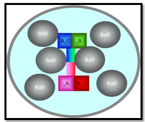
Figure 5. Ball-powder- ball collision of powder mixture during mechanical milling
Benjamin (1976)[41] demonstrated that true atomic level alloying occurred by mechanical alloying of Ni-Cr alloys by showing that the magnetic-behaviour of the mechanically alloyed Ni-Cr powder was identical to Ni-Cr alloys of the same composition prepared by conventional ingot metallurgy.
2.1.2. Ductile -Brittle Components
The evolution of microstructure during mechanical milling of ductile - brittle systems has also been described phenomenological[42-44]. The hard brittle powders are fragmented during milling, and the fragments are trapped at the boundaries between the ductile powders. As milling proceeds and the welds between ductile particles come closer together - and finally blend - a fine dispersion of the brittle phase results if it is insoluble in the ductile matrix, as inert oxides in ODS alloys. However, brittle intermetallics are also incorporated into, for instance, Ni-base ODS superalloys by mechanical alloying. The brittle intermetallics are fragmented but apparently alloy with the Ni-base matrix so that they are not resolvable by optical microscopy when mechanical alloying is complete.
Another example of the alloying of ductile / brittle components by milling wherein a homogeneous alloy is formed is the mixture of Zr (ductile) with NiZr2 (brittle) powder to form an amorphous Ni-24 at % Zr alloy[45]. Schultz et al (1988)[46] did not observe the alloying of brittle amorphous boron particles into Fe, Fe-Si or Fe-Zr powders by ball milling. In all cases the boron particles were dispersed in the metal matrix. In Fe-Zr-B the boron did alloy after annealing the dispersion below the crystallization temperature of the amorphous Fe-Zr alloy. Brittle Si did form an alloy with Fe during mechanical alloying. These observations presumably reflect the differences in the mutual solid solubility’s of the component. Boron has negligible solubility in Fe, while Si exhibits significant solid solubility in Fe. Similarly, the stable oxide disperse solids, such as Al2O3, Y2O3, ThO2, are essentially insoluble in the metal matrices of ODS alloys in which they are incorporated by mechanical alloying. Thus, alloying of ductile - brittle components during milling requires not only that the brittle particles become fragmented so that short-range diffusion can occur, but the brittle component must also have some solubility as indicated by either the stable or metastable phase equilibriums in the ductile matrix module.
2.1.3. Brittle- Brittle Components
It might be expected that mechanical alloying of brittle - brittle powder systems would not occur and that milling would simply reduce the brittle powder components size down to what is called the limit of combination. The grinding of brittle mineral powders to achieve fine particles for subsequent processing reaches a limit on particle size below which further fracturing stops the limit of combinations[47]. It has been suggested that this limit may be due to extremely small particles deforming plastically rather than fracturing, the increased cohesion between fine particles leading to aggregation, or phase changes in surface layers.
It has been shown; however, that milling of certain nominally brittle components can lead to homogeneous alloys. The brittle - brittle systems which have been studied in this regard include Si/Ge (which form solid solutions) (Davis and Koch, 1987)[48], Mn/Bi (which forms the intermetallic compound MnBi), (Davis et al., 1988)[49] and various mixtures of intermetallic compound such as NiZr2/Ni11Zr9 (Lee and Koch 1987)[50]. Davis and Koch (1987)[48] observed the formation of a Si-Ge solid solution on mechanical alloying of the pure components which are both nominally brittle at ambient temperature. The solid solution formation was detected by measurement of precise lattice parameters for Si and Ge as a function of milling time. The lattice parameters of Si and Ge move towards each other with increasing milling time until they merge to a single value, which is identical to that for the solid solution of this composition (Si-28 at % Ge) prepared by conventional metallurgical methods. Thus, it is possible to attain atomic level alloying by milling brittle components together. The microstructural evolution during milling differs markedly from the lamellar morphology of ductile components. A granular morphology is observed during mechanical milling of Ge and Si powder milled for two hours in a SPEX mill. It would appear that the harder Si particles are embedded in the softer Ge. It was also noted in the Si-Ge system that mechanical alloying was suppressed by milling in a vial cooled by liquid nitrogen. In this brittle- brittle system, thermal activation- diffusion is apparently a critical requirement for mechanical alloying. In contrast to this observation, mechanical alloying has been achieved at sub-ambient temperatures in ductile - ductile systems. This difference may reflect the longer diffusion distances required in the brittle - brittle granular vs. ductile - ductile lamellar geometry, and the enhanced diffusion paths provided by severe plastic deformation in ductile - ductile systems. The material transfer in the brittle powder agglomerates during milling may be related to the conditions that control the "limit of communication", as described above. When the limit of combination is reached in multi- component brittle powders, the conditions may be favourable for the cold welding or other material transfer mechanisms that result in mechanical alloying[51].

2.2. Mechanical Milling: Temperature Effects

The temperature during milling can depend on the 'kinetic energy' of the ball and the material characteristics of the powder and milling media. The temperature of the powder influences the diffusivity and defect concentration in the powder influencing the phase transformations induced by milling. Higher temperatures are expected to result in phases which need higher atomic mobility (intermetallics) while at lower temperatures the formation of amorphous phases is expected if the energy is sufficient. Low temperature can also enhance the formation of nanocrystalline phases.
The measured maximum temperature of the SPEX mill was 50℃ with 13 balls (40℃ without leads) and concluded the most of the heat comes from the motor and bearings [52].
Kimura and Kimura reported a maximum macroscopic temperature of 172℃ in the attritor ball mill[53]. Borzov and Kaputkin have measured a temperature in the range 100-215℃ for an attritor using SiC and diamond sensors [54]. Thus the macroscopic temperature during milling appears to be low and sensitive to the mill design. The microscopic temperature of the powder just after the impact can be realized very high, often exceeding the melting points of some of the component metals. As it is not possible to measure the microscopic temperature during milling, investigators look two approaches to estimate it. One of the approaches is to calculate it by appropriate models and the other is to infer the temperature from the structural, microstructural changes during milling[55].

3. Nanomaterials and Nanocomposites

3.1. Al-based Nanomaterials and Nano Composites

J. Sun et al[56] investigated the microstructural evolution of the ordered L12+DO22 multiphase Al67Mn8Ti24Nb1alloy by mechanical milling and subsequent annealing. The ordered L12+DO22 multiphase Al67Mn8Ti24Nb1alloy first transformed into disordered fcc supersaturated solid solution after 15 h milling and again into the full amorphous structure as the milling proceeded to 60 h. The full amorphization of the Al67Mn8Ti24Nb1alloy was resulted due to introduction of high dense nano-crystalline grain boundaries and the large internal lattice strain caused by the super-saturated dissolving of the Al3(TiNb) second phase in fcc solid solution. P. Nandi et al[57] synthesized amorphous and/or nanocrystalline Al-based alloys from elemental powder blends with the stoichiometry Al65Cu35-xNbx(x=/5-25 at.% Nb) by high energy planetary ball milling. The mechanical alloying of Al65Cu30Nb5, Al65Cu20Nb15and Al65Cu10Nb25powder blends for appropriate time (30-/50 h) in a planetary or shaker mill resulted into the formation of a single phase nanocrystalline disordered metallic phase, an amorphous alloy and a nano-aluminide mixture of NbAl3, and fcc-Nb solid solution or Nb(CuAl), respectively. Presence of Nb in appropriate amount played a crucial role for introducing adequate disorder and solid state amorphization of these ternary system. They showed that, mechanical alloying was a potential route of synthesizing Al-based nanocrystalline or amorphous matrix Al-Cu-Nb alloy powders/composites for applications below 350℃. By starting from the elemental powder M. Zawrah et al[58] investigated the microstructural and compositional evolution of Al93Fe3Ti2Cr2alloys via mechanical alloying. They studied the potential of the MA-processed Al93Fe3Ti2Cr2alloy for structural applications at both ambient and elevated temperatures. The nanocrystallization process of the Al alloy proceeded via an initial increase followed by a subsequent decrease in dislocation density to form nano-grains with a dislocation-free interior. I. Manna et al[59] reported the formation of amorphous and/or nanocrystalline products by mechanical alloying of Al65Cu35−xZrx(x = 5, 15 and 25at.% Zr) elemental powder by planetary ball milling up to 50h. Mechanical alloying of Al65Cu35−xZrx(x = 15, 25, 5at.% Zr) by planetary ball milling up to 50h led to the formation of a single-phase amorphous microstructure in Al65Cu20Zr15, nanocrystalline and amorphous mixture in Al65Cu10Zr25, and nanocrystalline intermetallic phases in Al65Cu30Zr5, respectively. Isothermal annealing of the final milled (50h) and amorphous Al65Cu20Zr15alloy at 400–800 K in vacuum for 2 h resulted the precipitation of nanocrystalline intermetallic phases. Al–Zn/Al2O3and Al–Zn–Cu/Al2O3 were prepared by T.G. Duraiet al[60] via reaction sintering of partially reacted oxide mixtures derived from a high-energy ball milling process. It was observed that the wear resistance of the milled composites was better than that of the unmilled composites, since Al2O3 particle size played important role in bearing the external load, and there was a good interfacial cohesion between Al2O3 particles and the matrix. They observed that the wear rate increased linearly with the applied load irrespective of the material and decreased with the increasing sliding distance. The coefficients of friction of the composites against EN32 steel decreased with the decreasing alumina particle size as well as the crystallite size of the matrix. Nanocrystalline Nb3(Al1-xGex) mixtures with x = 0, 0.3 and 1 were fabricated by E. Pusceddu et al[61] by wet mechanical milling using copper milling media and distilled water as a process control agent (PCA) with the intention of improving the yield, properties and the performance of these materials. Very high yields of nanocrystalline material were achieved but significant copper contamination. A typical grain size of a few nm was obtained for the Nb-Al-Ge mixtures after several hours milling. M. Khakbiz et al[62] synthesized the Al–B4C nano-composite powders by mechanical alloying. Firstly they milled the commercially available (0.7 μm) boron carbide (B4C) particles, in a attritor ball mill and prepared B4C nano-particles. Secondly the mechanical alloying was employed to synthesize metal matrix composite powders with a nanocrystalline Al 6061 alloy as the matrix and B4C as the reinforcement. Different amounts of B4C particles (5 wt.% and 10 wt.%) having various sizes of 90 nm (produced in the first part of study), 0.7 μm and 1.2 μm were mixed with different sized (21 μm and 71 μm) Al 6061 powder particles and were milled for different times. The results showed that the nano-sized B4C particles were fabricated when milled for 110 h. The size of powder particles in the milled powder mixture was affected by the initial size and content of B4C particles and Al powders. The crystal size of aluminum reached to 57 nm after 16 h milling of powder mixture and addition of B4C resulted in a finer grain size of Al in the Al + B4C mixture during the early stages of milling. High energy mechanical milling of a mixture of alumina and nanostructured Fe48Co52powders was used in producing an Al2O3-20vol%Fe48Co52composite powder by M.Yusop et al [63].
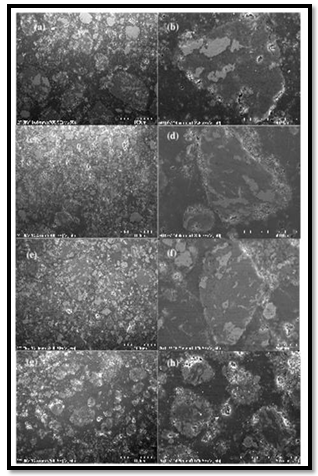
Figure 6. SEM images of cross-sections of powder particles produced after different milling times (a) and (b): 8 h, (c) and (d): 16 h, (e) and (f): 24 h, (g) and (h): 48 h. Reprinted with permission from[63] M. Yusop, D. L. Zhang, and M. Wilson, IOP Conf. Series: Materials Science and Engineering vol.4, pp. 012016, 2009
There was a significant reduction in Al2O3grain size after 24h milling up to 27nm and approached the alloy grain size with further milling whereas, the alloy particles were almost unchanged grain size throughout the process. After 24h, a small fraction of Al2O3 particles embedded into the alloy particles, forming a complex composite structure. Figure 6 shows the microstructures of the powder particles produced with different milling times and dark and light colors regions correspond to Al2O3 and Fe48Co52 phases, respectively. The severe deformation of Fe48Co52 phase was more pronounced after longer milling time. During subse quent milling, Fe48Co52 particles were incorporated into Al2O3matrix and became flatten, elongated, and exhibited ductility behavior. On the other hand, Al2O3was repeatedly fractured, cold- welded with Fe48Co52particles being trapped in between due to collision impact between milling media. There were a small fraction of Al2O3particles being trapped inside the Fe48Co52 particles which were in turn embedded in the Al2O3 matrix as shown in Figures 6(f) and 6(h). High energy ball milling was used by. Tousi et al[64] to produce a nanostructured Al matrix composite reinforced by submicron α-alumina particles. The addition of alumina particles as the reinforcement had a drastic effect on the size, morphology and pressability of the powder. The distribution of the alumina particles in the Al matrix reached a full homogeneity after steady state. They observed that the effect of the nanostructured Al matrix, the presence of submicron alumina particles and nanometeric particles caused by decomposition of PCA increased the hardness of powder up to 180 HV.
MM was utilized by D. Poiriera et al[65] to disperse nano- metric alumina (n-Al2O3) in an aluminum matrix. Al2O3/Al nanocomposite powders were produced for various alumina sizes and concentrations. The 10vol% n-Al2O3/Al powders displayed hardness values near five times higher than pure unmilled Al. It was observed that a decrease in the Al2O3 particle size from 400 to 4 nm increased the nanocomposite powder hardness by 11% probably due to in situ matrix strengthening.Aluminum matrix composites reinforced by two sizes of alumina particles (35 nm and 0.3 lm) were prepared by M. Tabandeh Khorshid et al[66] by wet attrition milling and hot forward extrusion processes. They evaluated the effect of the ratio of the nano- to submicron-sized particles (2:8, 3:7, 4:6, 5:5, and 6:4 in weight per- cent) on mechanical properties of the composites by micro-hardness and tensile tests. It was found that by increasing the nanoparticles content, the hardness and strength of the composites first increased and then decreased when the amount of the nanoparticle exceeded 4 wt.%. High-energy wet ball milling was employed by H.Ahamed et al[67] to synthesize nano- crystalline Al 6063 alloy powders reinforced with 1.3vol.% Al2O3, 1.3vol.% Y2O3 and 0.65vol.%Al2O3 0.65vol.%, Y2O3 at nano-size level. It was observed that the addition of ceramic nano particles into the aluminum matrix sustained the crystallite size reduction. Better particle size distribution was attained in Al 6063/Al2O3/Y2O3 nano-composite powder. Al–5vol.% SiC nanocomposite powder was produced by S.A. Khadem et al[68] by using attrition milling. It was found that the addition of nano size SiC greatly influenced the morphological characteristics of powder mixture, and also worked hardening of the powder to decrease the time taken to reach a steady state. Furthermore, Al became smaller crystallite size during ball milling of Al powder in the presence of SiC particles.

3.2. Mg-based Nanomaterials and Nanocomposites

Nanocrystalline and nano-/amorphous Mg1.9M0.1Ni (M5Ti, Zr,V) alloys were synthesized by T. Spassov et al[69] by mechanical alloying followed by annealingdepending on the milling parameters as rotation speed, time of milling and annealing (temperature and time of annealing) conditions different microstructures were obtained.The milled materials had hexagonal Mg2Ni crystal structure and the crystallites size of the milled as well as of the milled and annealed alloys was in the range of 10–20 nm. The heating of the as obtained materials above 700 K increased the grain size. High energy ball milling has been proved a suitable way for processing Mg based nanostructured material, especially when milling is carried out under a hydrogen atmosphere, which provides a nanostructured and hydrogenated final product. J.F.R. de Castro et al[70] investigated the structural evolution of Mg, Nb and a mixture of Mg–5 at.%Nb by reactive milling. They showed that Nb rapidly absorbed hydrogen, and formed the NbH0.9 phase whereas Mg was only partially transformed into ß-MgH2 and γ-MgH2 phases. When Mg–5 at.%Nb mixture was milled for 48 h, almost all Mg and Nb were transformed into hydridesindicating the catalytic effect of Nb on the hydrogen sorption of Mg. By utilizing the elemental powders of Mg, Al and Ti with polyethylene–glycol L. Lu et al[71] synthesized the Nanocomposite Mg5wt%Al– 10.3% Ti via mechanochemical milling. Nanoparticles were embedded in the Mg matrix and the grain size of the milled specimen was about 77 nm.TiH2 was also observed after milling and the concentration of TiH2increased after sintering. These nanocomposite showed an improvement in yield strength and ductility compared to their counterpart fabricated by using a conventional powder metallurgy process.
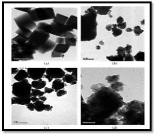
The structure and magnetic properties of spinel-related Mg-doped Li0.5Fe2.5O4 nanocrystalline particles prepared by milling a pristine sample for different times were investigated by Widatallah et al[72]. Mg-doped Li0.5 Fe2.5 O4 of the composition Li0.41Fe2.41 Mg0.17 O4 was prepared by sintering in air at 600℃ (12 h) a 5: 1 molar mixture of hydrothermally prepared Mg-doped α-Fe2O3 and Li2CO3. The material was then milled in air using a Retsch PM400 planetary ball mill with stainless steel balls for periods of 6.5, 15, 38 and 50 h keeping fixed the ball-to-powder mass ratio at 20: 1. TEM micrographs of samples obtained after milling for different times (Figure 7). In Fig. 7(a) the non-milled ferrite was mostly formed of cubic particles with an average size of ∼0.2 mm. Milling the material for 6.5 h resulted in irregular particle shape distributed over a broad size range extending from ∼40 nm to ∼0.3 mm (figure 7(b)). Further fragmentation and shape irregularity were observed for the sample milled for 38 h which was found to have a particle size distribution ranging between ∼20 nm and∼0.2 mm (figure 7(c)). After 50 h f milling (figure 7(d)) a mixture of spherical and irregularly shaped nanoparticles with an average size of ∼15nm was obtained. These nanoparticles tended to agglomerate forming grains that vary in size between ∼50 and ∼150nm. Nano-sized BaxMg1−xFe2 O4 ferrite particles less than about 150 nm were prepared by Y. Choi et al[73] by using self-propagating high temperature synthesis and mechanical ball milling. It was observed that as the ratio of BaO2to MgO in the initial powder composition varied from 0.25 to 4.0, coercive force decreased about 102%.
Figure 7. The TEM micrographs of the Mg-doped Li0.5 Fe2.5 O4 samples milled for (a) 0 h; (b) 6.5 h; (c) 38 h and (d) 50 h. The scale bar for micrographs (a)–(c) represents 0.2 μm; for micrograph (d) it represents 30 nm. Reprinted with permission from[72] H. M. Widatallah, C. Johnson, A. M. Gismelseed, I. A. Al-Omari, S. J. Stewart, S. H. Al-Harthi, S. Thomasand H. Sitepu, J. Phys. D: Appl. Phys. vol.41,pp. 165006, 2008
A nanostructured MgH2-0.1TiH2 material was prepared by ultrahigh-energy-high-pressure mechanical milling by Lu et al.[74]. The grain size of the milled MgH2-0.1TiH2 powder was approximately 5-10 nm with uniform distributions of TiH2 among MgH2particles. This composition significantly improved the kinetics of dehydrogenation and hydrogenation compared to commercial MgH2. Mg2Ni and MgNi alloys were synthesized by Mustafa Anik et al[75] by the mechanical alloying and their electrochemical hydrogen storage characteristics were also investigated. The MgNi alloy was mainly in the amorphous nature while Mg2Ni alloy was a mixture of amorphous and nano-crystalline structures. The amorphous MgNi alloy developed very fast and the maximum storage capacity was reached at 15 h ball milling, whereas the maximum storage capacity of Mg2Ni alloy was observed after at 40 h ball milling. Both the initial discharge capacity and capacity retention rate of MgNi alloy were much greater than those of Mg2Ni alloy.The nanocrystalline Mg-Al-Zn alloy were synthesized by Zheng et al[76] via a cryomilling and spark plasma sintering approach and its mechanical behavior and microstructure were alsoreported and discussed. Their results showed that cryomilling for 8 h yielded nc Mg agglomerates, approximately 30 μm in size, with an internal average grain size of approximately 40 nm. The cryomilled Mg powder was consolidated using spark plasma sintering at 250, 300 and 350℃ and a considerable increase in grain size at the particle interface and retained nc in internal particles was observed, resulting a bimodal microstructure. Inside of the coarse grains, nano-sized Mg17Al12 precipitates were observed.

3.3. Co-based Nanomaterials and Nanocomposites

Zhou et al.[77] reported that the initially ordered intermetallic compound Co2Si with orthorhombic structure was resulted in to anti-site disorder and nanocrystalline material through mechanically milling in a high-energy ball mill. The generation of anti-site disorder in Co2Si was confirmed by the continuous increase of magnetization by a factor often. The average crystallite size is about 8-10 nm after long milling time. Both anti-site disorder and grain boundaries were major sources of energy storage during ball milling. Ultrafine Co and Ni particles were prepared by mechanochemical processing by[78]. These uniform sized (10-20 nm) particles were obtained by the chemical reduction of cobalt and nickel chlorides during mechanical milling with Na. The excess of NaCl was used as a diluents to prevent the occurrence of combustion during milling. The magnetic properties of the ultrafine powders were reducted in magnetization relative to their bulk values and the coercivities were significantly increased. Elina Manova et al.[79] prepared cobalt ferrite, CoFe2O4, nanoparticles from pre-prepared layered double hydroxide carbonate, LDH-CO3, by mechanical milling and the particle size were controlled by the treatment time. The 5h milling of the LDH-CO3 resulted cobalt ferrite nanoparticles. Longer- term milling induced particle growth, while prolonged milling resulted in the formation of some cobalt metal. They showed that the magnetic properties exhibited a strong dependence on the particle size as a result of an unusual action distribution and of surface effect. By this method large scale CoFe2O4nanoparticles can be synthesized by the combination of co-precipitation under ultrasonic treatment and subsequent mechanical milling. The nano-crystalline rare earth doped WC/Co powder with grain size of 8.45 nm was prepared by L. Sha et al[80] by high energy ball milling. The results showed that adding trace rare earth elements into carbides is effective to minimize the grain size of WC/Co powder. They observed that the grain size of rare earth doped powder became two times smaller as compared with the undoped powder within ball milling times of 25–45 h. The rare earth doped powder with grain size of 8.45 nm was obtained after 45 h ball milling. The Fe48Co48V4alloy was synthesized by B. Chitsazanet al[81] in a planetary high-energy ball-mill under an argon atmosphere. Inter-metallic Co3V was also observed during the mechanical alloying. The lattice parameter decreased up to 55 h of milling time with an oscillation and then increased from 55 to 125 h of milling time.

3.4. Ni- based Nanomaterials and Nano Composites

Doppiu et al.[82] demonstrated that Ni can be formed controllably by partial reduction of NiO upon reactive ball milling, leading to Ni-NiO nanocomposites. Mechano- chemical reduction of NiO was carried out at room temperature by ball milling under H2 atmosphere. During the milling, NiO gradually converted into Ni, without formation of any intermediate phases. The amount of Ni and its crystallite size were tuned by the milling parameters, which led to the formation of Ni-NiO (metal- oxide) nanocomposites. Besides the initial microstructure of the NiO powder also played an important role in the reduction rate and on the final microstructure of the nanocomposites. Their results indicated that the mechanically induced defects had a strong influence on the kinetics of the reduction process. Nanocrystalline Ni0.5Zn0.5Fe2O4 spinel ferrite with a grain size of 50 nm was prepared by N Sivakumar et al[83] by using the ceramic method. The grain size was further reduced to 14 nm by milling the as-prepared ferrite particles in a high-energy ball mill. The increase in conductivity of the milled sample was, therefore, attributed to conduction by the oxygen vacancies created by mechanical milling. The higher values obtained for the activation energy for conduction were also evidence for the oxygen vacancy conduction. The increase in Neel temperature from 573 to 611 K on reducing the grain size from 50 to 14 nm were explained based on the changes in the cation distribution. The observed increase in the coercivity of the milled sample has been attributed to surface anisotropy of increasing number of ions on the surface. M. N. Mancheva et al[84] synthesized the nanocrystalline NiWO4 powders by mechano-chemical activation. A stoichiometric mixture of NiO and WO3 in a 1:1 molar ratio was subjected to intense mechanical treatment in air using a planetary ball mill for different periods of time. It was found that 7.5 h of milling of the reagents led to complete crystallization of single nanostructured phase NiWO4at room temperature. NiFe-CNT and Ni3Fe-CNT nanocomposites were fabricated by S. Azadehranjbar et al[85] by high energy mechanical alloying method. As obtained ball milled powders were heat treated at 500℃ for 1 h to release the milling induced stresses. Bulk samples were prepared by sintering of cold pressed (300 MPa) samples at 1040℃ for 1 h. The hardness value of as-milled NiFe and Ni3Fe powders reached to 660 and 720 HV, respectively. It was proposed that the introduction of CNTs at the matrix led to decrease of particles size of composites and therefore the size of porosities in the bulk samples hence the bulk density of the samples increased.

3.5. Cu-based Nanomaterials and Nano Composites

Nano-crystalline copper with a mean crystallite size of 27 nm was synthesized by S. Sheibani et al[86] through solid state reduction of Cu2O by graphite using high energy planetary ball mill. Mechanochemical reduction of Cu2O with graphite resulted in a continuous decrease in the Cu2O mean crystallite size and an increase in internal strain during initial stage of milling operation. They observed that as the milling time was increased, fine Cu powders are produced and the crystallite size and internal strain of the copper particles changed irregularly with further milling time due to the progressive formation of copper during milling. Prolonged milling resulted in the agglomeration of the copper powder. The mean crystallite size of the copper produced after 30 h of ball milling was about 27 nm. High energy mechanical milling (HEMM) of a mixture of Cu powder and Al2O3 nanopowder was used to produce Cu-(2.5-10)vol.%Al2O3 nanocomposite powders with a ultrafine grained or nanocrystalline Cu matrix by D. L. Zhang et al[87]. High energy mechanical milling was effectively used to disperse (2.5-10%) vol.% Al2O3 nanoparticles into a ultrafine grained or nanocrystalline Cu matrix. Using larger diameter balls or increasing the volume fraction of Al2O3 nanoparticles to 7.5% or higher allowed, synthesis of Cu-Al2O3 nanocomposite powders with nanocrystalline Cu matrix.Cu and Al2O3 were used as starting powders and two milling routes were used: in Route 1, the powder mixture was milled for 12 hours using 60 balls with a diameter of 12.5mm; and Route 2 was Route 1 plus further milling for 12 hours using 12 balls with a diameter of 12.5mm and 6 balls with a diameter of 25mm. In both routes, the ball to powder weight ratio was 5:1.
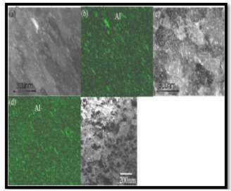
The samples of the milled powders were annealed for 1 hour at different temperatures in a tube furnace which has a vacuum of 10-6 bar. It was observed that 5vol.%Al2O3, almost uniform dispersion of Al2O3nanoparticles in the Cu matrix was achieved with a relatively short time of 6 hours of milling, as shown in Figures 8(a) and (b).
Increasing the milling time to 12 hours causes little change in terms of the dispersion of the Al2O3 nanoparticles (Figure 8(c) and (d)). In the Figure 8, the bright particles are Al2O3 nanoparticles. It appeared that in with a short milling time of 6 hours, the Al2O3 nanoparticles are predominately distributed along the grain boundaries, whereas with a short milling time of 12 hours, a large fraction of the Al2O3 nanoparticles are distributed inside the grains. For Cu- 5vol.%Al2O3, with Route 1 milling of up to 12 hours, ultrafine grains with sizes in the range of 100- 300nm formed. The second 12 hours milling using larger balls in Route 2 caused significant refinement of the grains into the size range of 50-150nm, as shown in Figure 8(e). Nanostructured Cu-7.5vol.%Al2O3 and Cu-10vol.%Al2O3 composite powders were produced by Mukhtar et al [88] from a mixture of Cu powder and Al2O3 nanopowder using two routes of high energy mechanical milling. The as-milled and annealed nanocomposite powder particles showed little increase of the Cu matrix grain sizes and decrease of micro-hardness after annealing at temperatures up to 400℃. However significant coarsening of Cu grains and Al2O3 nanoparticles and sharp decrease of micro-hardness was observed with increasing annealing temperature to 500℃.This confirmed that Cu-7.5vol % Al2O3 nanocomposite was thermally stable at temperatures up to 400℃. The degree of microstructure coarsening and micro-hardness decrease with annealing of the 24 hours milled (Route 2) powder was clearly smaller than that of the 12 hours milled (Route 1) powder annealed under the same condition.
Figure 8. (a)-(d) STEM images and elemental X-ray mapping for Al of the microstructure of typical particles in Cu-5vol% Al2O3 nanocomposite powders milled for different conditions: (a) and (b) milled for 6 hours; (c) and (d) milled for 12 hours and (e) TEM bright field image of the microstructure of Cu-5vol% Al2O3 nanocomposite powder particle milled for 24 hours. Reprinted with permission from[87] D. L. Zhang, A. Mukhtar, C. Kong, P. Munroe, Journal of Physics: Conference Series vol.144 pp.012028, 2009
P. Sahani et al[89] synthesized Cu99Cr1, Cu94Cr6, Cu99Cr1– 4%SiC and Cu94Cr6–4% SiC (∼30 nm) nanocomposites via ball-milling for 50 h in a stainless steel grinding media. Analysis of crystallite size, lattice microstrain and lattice parameter of Cu revealed that the dissolution of Cr increased up to 1 at.% in presence of nanosize SiC particles during milling. Cu–Zr alloys were developed by M. Azimi et al[90] by the mechanical alloying process. Pure copper powders with different amounts of 1, 3 and 6 wt% of commercial pure zirconium powders were mixed and milled in a planetary ball mill for different milling times of 4, 12, 48 and 96 h. Results showed that the lattice parameter of copper increased with increasing milling time. Their average size increased initially and reached a maximum value then it decreased at longer milling times. After 12h of milling, crystal sizes were in the range of 33–97 nm and increasing of Zr content in initial powder mixtures facilitated nano- structure development in Cu–Zr powder mixtures.

3.6. Ti- based Nanomaterials and Nano Composites

S. Indris et al [91] prepared nanocrystalline powders of the anatase TiO2 as well as the rutile TiO2 modification by high-energy ball milling of the coarse grained source materials for 4 h. The average grain size was varied via the milling time in the range from some micrometers down to about 20 nm. They showed that the catalytic activity of TiO2 powders was strongly influenced by the powder morphology and the electronic structure of the samples. It was observed that for all milling times the decrease of the grain sizes led to an increase in the BET surface area. Wang et al[92] reported the synthesis of stable Ti50Zr50 binary nano-composite of grain size about 7.6 nm by the roller vibration milling with a batch volume about 170 g at room temperature. The composite remained the basic hexagonal feature, but the axial ratio was much smaller than that of the ideal hexagonal close-packed structure and the standard value of Ti and Zr. For the alloying and insertion into the Ti matrix, the size reduction of Zr was very important. The grain size of Ti varied periodically with time, but the period was dependent on the grain size of Zr. L.X. Qiu et al[93] synthesized of TiN–TiB2 nano-composite by mechanical milling of mixture of Ti and hexagonal boron nitride (h-BN) and subsequent sintering under high pressure and high temperature. A TiN–TiB2 composite was fabricated by ball milling of the mixture for 70 h and then sintering at 5 GPa, 1300℃. X. Zhao et al[94] used mechanical milling to treat the crystalline Ti2Ni alloy prepared by solid-state sintering. The particle size of the alloy decreased first and then increased after the milling. Moreover, MM contributed to a decrease in grain size and the formation and increase of the amorphous phase by increasing the milling time, resulting in improvements of the antipulverization ability and cycle life after the milling. M. Ali et al[95] synthesized nano-structured TiC from mixtures of TiO2 and graphite through high- energy mechanical milling and subsequent heat treatment at a temperature that was considerably lower than that used in conventional carbothermal reduction synthesis of TiC. TiO2 powders mixed with graphite were milled in a planetary ball mill for 30–90 hand then milled mixtures were heat treated at 1200℃ and 1300℃ for 60 min. The crystallite size of TiC increased with increasing milling time after heat treatment. A nano-composite structure containing of an intermetallic matrix with dispersed Al2O3 particles was obtained by S. Alamolhoda et al[96] via mechanical activation of TiO2 and Al powder mixture for different time and subsequent sintering. The results revealed that the reaction began during milling by formation of Al2O3 and L12Al3Ti and further milling caused partial amorphization of powder mixture. Phase evolutions of the milled powders after being sintered revealed that by increasing the milling time and formation of L12Al3Ti in the milled powder, intermediate phase formed at 500℃ changes from DO22Al3Ti to Al24Ti8 phase. Increasing the milling time from 8 to 30 h caused formation of finer microstructures in composite and a reduction in crystallite size of TiAl phase from about 70 to 18 nm. Mashhadi et al [97] reported the synthesis of titanium nitride solid solution by the reduction of aluminum nitride with titanium by MM using a planetary ball mill. A nanostructure composite of in-situ titanium nitride solid solution was produced through exchange reaction between Ti and AlN. It was observed that, with increased milling time, Al resulted from decomposition of aluminum nitride dissolved in the Ti lattice, led to the formation of Ti(Al) solid solution and a reduction of the Ti lattice interplanar distance. Consequently, the Ti(Al) solid solution reacted with nitrogen to form in-situ Ti(Al)N nano particles. The milled powder had a spheroid shape and a very narrow size distribution of about 1 μm at the end of milling. In-situ Ti(Al)N particles with an average size of 10 nm were attained at a ball-to-powder weight ratio of 10:1 and a Ti:AlN molar ratio of 1:1.

3.7. C-based Nanomaterials and Nano Composites

Awasthi et al[98] reported the formation of carbon in different nanoparticle forms by ball-milling of graphitic carbon. Ball-milling of graphite was carried out in attritor ball mill at room temperature in hexane medium for different times i.e. 24, 48 and. The self-coagulated carbon agglomerates were obtained in the case of 24 and BMC samples. The formation of coiled nanotubes and nanofibres were observed in the BMC sample. The BMC samples with and without nickel (Ni) catalyst were subjected to hydrogenation cycling also. The vibratory ball mill was used to decrease the single-wall carbon nanotubes length and to increase their specific surface area by N. Pierard et al[99]. Different measurements indicated that the optimum time of treatment seems to be 2 h. After that, the SWNTs quality decreased, with a complete disruption of the tubular structure leading to multi-layered polyaromatic carbon materials observed after 50 h.
H. G. Connan et al[100] reported the formation of new nanocarbons by rod milling and annealing of graphite in the presence of yttrium. They investigated the mechanisms of ordering and disordering graphite in the presence of 1% and 10% yttrium through mechanical activation and subsequent thermal annealing at 1350℃ for 6 h. Graphite nano-sheets with high aspect ratio, having a thickness of the order of 10 nm, high shape asymmetry, and a well crystalline order, were produced by Antisari et al[101] by a mechanical method based on the grinding of graphite powder under low energy pure shear milling using water as a lubricant. The gentle plastic deformation activated the plastic slip mainly on the easy glide basal planes without any appreciable increase in the density of crystal defects. Consequently, the resulted nano-sheets had relatively well preserved crystal order. A. Touzik et al[102] studied the structural transformations and amorphization of graphite upon high-energy ball-milling under argon and hydrogen atmosphere.Up to approximately 40% of the adsorbed nitrogen was stored in ultra micropores with diameter less than 0.8 nm and it was independent from milling atmosphere. Micro and mesopores with a radius under 4nm were pre- dominantly formed at the early stage of milling. Breakage of graphite stacks increased fraction of larger mesopores. The samples milled under hydrogen atmosphere contained a large fraction of pores with radius about 4 nm even after long milling time. They observed that hydrogen inhibited breakage of graphite sheets, and preserved the crystal structure of graphite and suppressed the specific surface area growth during the milling process. Single-walled carbon nanotube (SWCNT)/silicon composites were produced by J. Y. Eom et al [103] from the purified SWCNTs and Si powder by high-energy ball-milling and then electrochemically inserted with Li using Li/(SWCNT/Si) cells. The SWCNT/Si composites produced by high-energy ball- milling exhibited a structure in which Si particles were densely packed by the flattened and fractured SWCNTs.
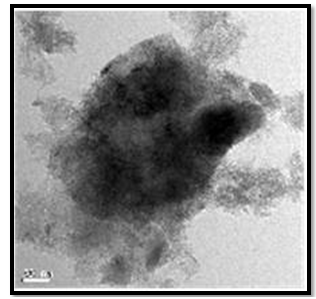
Figure 9. TEM image of the SWCNT/Si composites after ball-milling for 60 min, demonstrating clearly that the fractured and flattened SWCNTs were densely packed around Si particles by ball-milling. Reprinted with permission from [103] J.Y. Eom and H.S. Kwon, ACS Appl. Mater. Interfaces, vol.3, pp.1015, 2011
In addition, the SiC compound formed on the SWCNT/Si interface made a strong contact between SWCNTs and Si particles. Figure 9 is the TEM image of the SWCNT/Si composites after ball-milling for 60 min, demonstrating clearly that the fractured and flattened SWCNTs were densely packed around Si particles by ball-milling. The enhanced capacity and cycle performance of the SWCNT/Si composites produced by high-energy ball-milling were due primarily to the fact that SWCNTs provided a flexible conductive matrix, which compensated for the dimensional changes of Si particles during Li insertion and avoided loosening of the interparticle contacts during the crumbling of Si particles. The ball-milling contributed to a decrease in the particle size of SWCNTs and Si particles and to an increase in the electrical contact between SWCNTs and Si particles in the SWCNT/Si composites.

3.8. Some Other Nanomaterials and Nano Composites

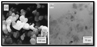
Lee et al[104] studied the Phase evolution of Fe2O3 nanoparticle during high energy ball milling. High-energy ball milling of α-Fe2O3 powder was performed in a stainless steel attritor at a speed of 300 rpm for 10–100 h. The powder-to-ball mass ratio was 1:50 with a powder mass of 100 g. Figure 10 shows micrographs of (a) as received powder observed by SEM and (b) 100 h ball-milled Fe2O3 by TEM. Their results revealed that the prolonged milling remarkably reduced particle size from 1 mm in as received powder to about 15 nm in 100 h ball milled powder. T. P. Bobin et al [105] investigated the chemistry and structure of nanosized silicon as-obtained by a high energy ball milling process. They investigated Si/SiOx suspensions on glass surfaces as a function of pH in a variety of oxidizing agents and atmospheres. For pH below 5 and in the absence of H2O, the Si-OEt groups present on the surface of these nanoparticles got protonated and attracted to a less positively charged glass substrate.
Figure 10. Micrographs of the ball-milled α-Fe2O3 powders with different milling times; (a) as-received and (b) 100 h. Reprinted with permission from [104] J.S. Lee, C.S. Lee, S.T. Oh and J.G. Kim Scripta mater. Vol.44, pp.2023, 2001
H. Zhang et al[106] synthesized isotropic TbMn6Sn6by mechanical milling and subsequent annealing. The coercivity of these materials was much larger than that expected from magneto crystalline anisotropy. Lee et al[107] studied the consolidation behavior and the mechanical properties of L12 phase (Al+12.5at.%Cu)3Zr intermetallic powders with a nanocrystalline microstructure. They showed that the (Al+12.5 at.%Cu)3Zr powders prepared by Planetary Ball Milling (PBM) could be consolidated to full density by Spark Plasma Sintering (SPS) at a lower temperature than the conventional consolidation temperature of zirconium trialuminide. Their study revealed that the L12 phase was maintained during the SPS process and the average grain size of the L12 phase specimens was 8.9 nm which is one of the smallest grain sizes for the nanocrystalline bulk specimens prepared by various consolidation methods. The micro- hardness was measured to be 975.8 Hv and this value was almost three times higher than that of the micro grain sized specimen. On the other hand, the average fracture toughness was lower than that of larger-grain bulk specimens. Their results indicated that refining the grain size to a nano level was not beneficial for increasing the fracture toughness of brittle intermetallics, however, the fracture toughness could be enhanced by introducing heat-treatment after consolidation.Using the physical high-energy ball milling technique,a new form of nanosized SrTiO3 semiconducting oxide material with an average crystal grain size of 27 nm were synthesized by Hu et al[108]. They found the unique presence of the singly charged “O-” ions in the lattice oxygen sites of the nano-range crystal grain material. They showed that this unprecedented and interesting discovery was expounded on the new oxygen sensing mechanism for the near 1/2 slope gradient in the logarithmic relationship of the electrical conductance with the oxygen partial pressure. The derived SrTiO3 oxygen gas sensors were found to operate near to the human body temperature (40℃). High-energy mechanical milling, followed by spark plasma sintering was used by Xu et al[109] to prepare a single-phase β-sialon nanoceramic, Si5AlON7.
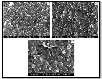
Figure 11. Fracture surface of a milled sample after sintering at different temperatures for 5 min. (a) 1550℃, (b) 1600℃, (c) 1650℃. Reprinted with permission from[109] X. Xu, T. Nishimura, N. Hirosaki, R.J. Xie, Y. Yamamoto and H. Tanaka Nanotechnology, vol.16 , pp.1569, 2005
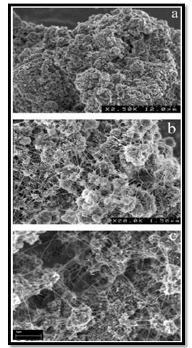
They reported that after milling, the starting powder mixture (Si3N4, AlN, Al2O3) was mostly transformed into an amorphous phase that contains a large number of well- dispersed nanocrystalline β-Si3N4 particles. They showed that milling promoted the mixing and reaction among the starting powders; β-sialon grains with the designed composition were formed directly through precipitation from the homogeneous amorphous phase on the nanocrystalline β-Si3N4 particles. Figure 11 shows the fracture surfaces of dense ceramics sintered at different temperatures starting from milled powders. Milling also improved the sintering ability of the starting powders, so the densification temperature was lowered by about 100℃ compared with that for as-received powders. They obtained a homogeneous microstructure composed of equiaxed β-sialon grains with a diameter of about 50 nm after sintering at 1550℃ for 5 min. They concluded that mechanical milling, followed by spark plasma sintering is effective method for fabricating β-sialon nanoceramics. Synthesis of free standing nanostructured silicon carbide films through spray pyrolysis of ball-milled silicon were reported by Singh et al[110]. In that work we employed a two-step process; 1) ball milling of silicon, and 2) spray pyrolysis of ball milled silicon in hexane at 1000± 1100℃ in an argon atmosphere. Silicon powder (99.99 %, particle size 0.05mm) was ball-milled in an attritor ball-mill at 400 rpm for 30 h in hexane. It was found that slurry of ball-milled silicon in hexane was produced as a result of the milling. This slurry was sprayed into a silica tube at high temperature (800±1100℃) under an argon atmosphere. The results revealed that the optimum SiC formation was obtained at a temperature of 1000-1100℃. Nanocrystalline FePt powders were prepared by Lyubina et al[111] using mechanical ball milling at liquid nitrogen temperature. They showed that depending on the milling time, either a lamellar (multilayer-type) structure of Fe and Pt, or A1 FePt or an intermediate structure, consisting of fine lamellae of Fe and Pt with A1 FePt formed at their interfaces was obtained.On annealing at temperatures just above 310℃, combined solid state reactions become activated resulting in the formation of L10 FePt phase and, in the case of the 2 h milled powder, additional Fe3Pt and FePt3 phases. The amount of heat evolved during the transformations, decreases from about 110 to 70 J/g and 55 J/g as the milling time increases from 2 to 5 and 7 h. They proposed that diffusion over the grain boundaries was the determining factor for the phase transformations, ordering and grain growth. P.P. Chinet al[112] reported that the high-energy mechanical milling of the mineral FeS2 pyrite as the starting material lead to the formation of sub-micron particles with nano-scaled grains. The use of the solid dispersion medium NaCl gave well-dispersed FeS2 nanoparticles and it also promoted the formation of fine particles. The as-milled powder consisted of nanosized particles having size around 10 nm. Multiwalled boron nitride nanotubes were produced in high yield by Jun Yu et al[113] by using a ball milling-annealing method. These thin boron nitride nanotubes with a diameter less than 10 nm were produced by ball milling-annealing method in which amorphous boron was first ball-milled for 150 h in a NH3 atmosphere and subsequently annealed in NH3. Boron nitride nanotubes had well-defined cylindrical structures and did not contain any metal particles or other structures such as bamboo tubes etc, which suggested that boron nitride nanotubes can be formed without metal catalyst and higher yield were achieved by using higher annealing temperatures and longer annealing times. In their method amorphous boron powder was used as the starting material and anhydrous NH3 was utilized as the reaction gas for both milling and annealing processes. First the amorphous boron powder was ball milling for 150 h at room temperature in ammonia gas and then annealed in NH3 gas at 1200℃ for 8 h. Figure 12a is the SEM images of as obtained milled powder and Figure 12b, reveals a large number of thin fibers from the surface of the aggregates/clusters. The thin nanotubes had a diameter less than 10 nm and were several micrometers long. The SEM image in Figure 12c shows that thin nanotubes were also formed inside clusters, which suggested that the powder-like clusters consisted of a large number of thin nanotubes and particles. CdTe nanocrystals were fabricated by Tan et al [114] by a mechanical alloying of elemental Cd and Te mixture powders for 27 h. The mean particle size of uncapped CdTe nanocrystals was estimated to be 23 nm for the 4.5 h sample and 3.5 nm for the 50 h milling sample. The result also confirmed the formation of a TeO2 thin layer on the surface of the particles. Nanocrystalline Nd12Fe82B6 (atomic ratio) alloy powders with Nd2Fe14B/α-Fe two-phase structure were prepared by Gang et al[115] by HDDR combined with mechanical milling. The results showed that, by milling in hydrogen for 20 h, the matrix Nd2Fe14B phase of the alloy was fully disproportionated into a nano-structured mixture of Nd2H5, Fe2B, and α-Fe phases with average size of about 8 nm, and that a subsequent desorption– recombination treatment at 760℃ for 30 min led to the formation of Nd2Fe14B/α-Fe two-phase nanocomposite powders with average crystallite size of 30 nm.
Figure 12. SEM images taken at different magnifications from the sample, after first ball milling for 150 h and subsequent annealing at 1200℃ for 8 h in NH3. Reprinted with permission from [113] J. Yu, Y. Chen, R. Wuhrer, Z. Liu, and S. P. Ringer, Chem. Mater., vol.17, pp.5172, 2005
Nano-sized Cu-doped TiO2 powders were prepared by Park et al[116] using mechanical alloying. Nanocrystalline Cu-doped TiO2 powders were prepared by MM and homogeneous precipitation process at low temperature (HPPLT). They measured the photocatlytic activity of Cu doped TiO2 powder for 4-chlorophenol photo degradation. The Cu doped powder had higher reaction ability than that of P-25 and HPPLT. It cause that the energy level was induced in TiO2 band gap by Cu-doped.Their results showed that 2.5 wt% of Cu element entered uniformly into the rutile TiO2 lattice with the average grain size less than 15 nm. The Cu-doped rutile TiO2 had new emission peak at 448 nm indicating the decrease of the bandgap energy of rutile TiO2. It exhibited an absorption edge at 480–490 nm longer than that for rutile TiO2 powder and led to a two times faster degradation of 4-cholorophenol. Wang et al[117] reported a new procedure for the direct synthesis of metal complex hydrides using high pressure ball milling and used it as hydrogen storage material. They showed that metal complex hydrides, NaAlH4 and LiAlH4, were synthesized through hydrogenation of their respective metal hydrides, NaH and LiH, with Al, both in the presence of a catalyst and in the presence of a liquid complexing agent. Their procedure involved three steps: blending the TiCl3 catalyst precursor with reactants using dry high-pressure ball milling (HPBM) in hydrogen, hydrogenation using HPBM in hydrogen and tetrahydrofuran (THF), and vacuum filtration and drying. Essentially, pure NaAlH4 and LiAlH4 products were produced in high yield at ambient temperature and near ambient pressure. Nanoparticles of Fe and Nd-Fe-B alloy with sizes less than 20 nm were fabricated by H. G. Cha et al[118] by a high-energy ball- milling process in the presence of surfactant and organic carrier liquid. It was also observed that the Fe and Nd-Fe-B alloy nanoparticles were phase-transformed from an amorphous to crystalline state by a heat treatment. This phase transformation led to a hard-phase magnetic property. Fe and Nd2Fe14B were used as starting material and anhydride methanol was used as a solvent whereas oleic acid CH3(CH2)7CHdCH(CH2)7COOH) served as surfactant during milling. First the rod-shaped nanoparticles were obtained by milling Fe and Nd2Fe14B powders, then heat-treated Nd-Fe-B alloy nanoparticles consisted of two phases, Nd2Fe14B and R-Fe phases. Nano-size particles of barium hexaferrite were synthesized by Ataie et al[119] by mechano-combustion after milling of intermediate products obtained in the sol–gel combustion process using nitrate–citrate gels prepared from metal nitrates and citric acid. The effects of precursor milling conditions on the phase evolution, crystallite size and annealing behavior of the products were also investigated by them.γ-Fe2O3 phase was present as a major phase and BaCO3 as a minor phase in as-burnt powder and mechanical milling transformed it from γ-Fe2O3 to α-Fe2O3. The rate of this transformation was strongly affected by milling conditions. Barium hexaferrite started to form at 700℃ and fully formed at 1000℃ for milled sample under the optimum milling conditions although it was hard to get the single phase of barium hexaferrite by this method under the given experimental conditions. For the formation of pure BaFe12O19, a subsequent heat treatment at 900℃ or above was required.C. Poinsignon et al[120] synthesized the nanometric tetragonal β-MnO2 by high energy ball milling (BM) and spray pyrolysis (nano-β) and studied its electrochemical response. Zinc oxide nanoparticles were synthesized by K Vojisavljevic et al[121] by milling in a planetary ball mill with a zirconia milling assembly for up to 5 h in air. The deviation of the lattice parameters from single crystal values was related to defect creation and increase of strain inside the hexagonal lattice of milled ZnO nanoparticles.
Scholz et al [122] studied the effect of mechanical milling on structure and reactivity of thermodynamically stable rhombohedral phase of aluminum fluoride (α-AlF3). α-AlF3 was used by them as starting material to produce nanostructured powders by high-energy ball milling. The mechanical activation of α-AlF3 resulted in considerable changes of particle sizes and shapes. Their results revealed that the mechanically activated samples, under the conditions applied here, are nanocrystalline. They found the formation of Lewis acid and Brønsted acid sites as a consequence of the mechanical impact. Dry-milling produced mainly Lewis acid sites whereas air-milling resulted in both Brønsted and Lewis acid sites. Catalytic test reactions using milled α-AlF3 as solid catalyst proved experimentally the theoretically suggested catalytic activity of nanosized AlF3 particles as a result of high structural distortion brought into the solid by milling.
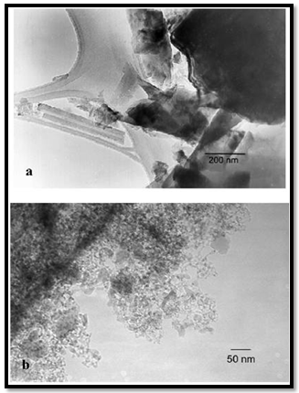
Figure 13. TEM micrographs of (a) unmilled crystalline α -AlF3, showing needles and particles of different size and shape, and (b) α -AlF3 milled for 16 h in a planetary mill with particles of a diameter of 50 nm and smaller. Reprinted with permission from [122] G. Scholz, R. Konig, J. Petersen, B. Angelow, I. Dorfel, and E. Kemnitz Chem. Mater., vol.20, pp. 5406, 2008
The TEM micrographs of unmilled α-AlF3 and dry-milled α-AlF3 are given in Figure 13. Both the unmilled (Figure 13a) and the milled sample (Figure 13b) consisted of the stable rhombohedral phase of α -AlF3. Differences between the two samples can be found only in the particle size and shape. The starting material contains irregularly formed particles up to needles ranging from 100 nm to 10 μm in size (Figure 13a). The milled sample consisted of particles with a distinctly diminished size beginning with 10 nm, and only a few numbers in the range of 200-400 nm (Figure 13). The smaller particles are spherically shaped. Even the very small particles consist of nanocrystalline α -AlF3, and an amorphization could not be established applying the present milling conditions.
M. Glushenkovet al[123] used the mechanical milling followed by annealing for the formation of V2O5 nanorods. They reported that the nanorods were formed through a controlled nanoscale growth from the nanocrystalline V2O5 phase created by a ball milling treatment. The nanorods were grown along the [010] direction and were dominated by {001} surfaces. They got large quantity production of nanorods when the annealing process was conducted in a fluidized bed. Spherical nano Ti(C,N) powder with average particle size of below 100 nm was synthesized from nano anatase/carbon black mixtures by Xiang et al [124] employing mechanical milling activation and subsequent carbothermal reduction– nitridation (CRN) reaction. Their results showed that CRN reaction of anatase was enhanced by pre-milling the starting powders. Thus, onset formation temperature and holding time of Ti(C, N) decreased from 1300℃ to 1150℃ and from 4 h to 2 h, respectively. Their results revealed that compared with low-energy mechanical milling, high-energy mechanical milling lowers reaction temperature and reduces reac- tion time of nano anatase CRN.Nano-sized BaxZn1-xFe2O4 ferrites were prepared by Choi et al[125] using a self- propagating high-temperature synthesis (SHS) reaction, followed by mechanical milling. The combustion temperature and the propagating rate during the SHS reaction were in the ranges of 860–1208K and 4.9–6.0mm/s, respectively. Their final products were crystalline Ba0.23Zn0.77Fe2O4 and Ba0.48Zn0.52Fe2O4 phases with an average particle size of less than about 100nm. As the initial composition ratio of BaO/ZnO and the oxygen partial pressure during the SHS reaction changed from 0.5 to 2.0 and 0.025 to 0.1, they found that the maximum magnetization (Ms), residual magnetization (Mr) and coercive force (iHc) changed by about 233%, 372% and 82%, respectively.
They showed that that the changes of the magnetic properties and permeability were related to the non-stoichio- metries of the ferrite powders. Zhu et al [126] developed a new mechanical alloying method to prepare nanopowder of metals and tungsten carbide. A milling method (P-milling) combining mechanical milling and dielectric barrier discharge plasma were established by them.They reported that the metal powder prepared by P-milling had a lump-like morphology with very high specific surface area. The lump- like powders were agglomerate of fine primitive particles. This unique morphological feature of powder makes it high active and favorite solid state reaction. They demonstrated that WC could be formed at a carburizing temperature much lower than that in conventional carburizing of W when the W–C powder mixture was pretreated by P-milling. The formation of the unique morphology of the powders was resulted from synergetic effect of mechanical milling and dielectric barrier discharge plasma, which is characterized by concurrent action of high temperature and stress on the powder in a very short time. Zhu et al[127] studied the effect of Ni/C ratio on the structures and hydrogen storage properties of Mg-Ni-C prepared by hydriding combustion synthesis and mechanical milling. They prepared Mg-Ni-C composite by first ball milling the powder mixtures of carbon aerogel and nano-Ni, and then mixed with magnesium powder followed by hydriding combustion synthesis (HCS). The HCS product was further treated by mechanical milling for 10 h. They found that the improved hydriding/dehydriding properties were related greatly to the Ni/C ratio and the structures of the composite systems. They proposed that Ni and carbon aerogel have a synergistic catalytic effect on improving the dehydriding properties of the Mg-based hydrogen storage materials prepared by HCS þ MM.
A synthetic route was developed by Z.Chen et al[128] to transform micrometer-sized Sb powders into new Sb-sandwiched nanocomposite particles (SiC-Sb-C) with Sb nanoparticles pinned on rigid SiC nanocores and surface- coated with carbon by use of a high-energy mechanical milling technique at ambient temperature. The as-prepared SiC-Sb-C material showed not only high reversible capacity retention after 120 cycles but also a quite high rate capability when used as anode materials for rechargeable lithium batteries.Poly (vinylidene fluoride-co-hexafluoropropylene) porous polymer electrolyte membranes were prepared by G. G. kumar et al[129] by the solvent-nonsolvent evaporation technique. The particle size and molecular weight of the polymer were greatly varied with the ball-milling technique, and the electrochemical properties of the polymer electrolyte membranes were examined as functions of these variations. It was observed that a decrease in the particle size and molecular weight of the copolymer effectively absorbs or allows high acidification and increases the segmental motion of ions, respectively. Due to simultaneous synthesis of WC and W2C phases in most of the synthesis processes and lower mechanical properties of W2C than WC, M.Razavi et al[130] synthesized nano-crystalline WC single phase by means of mechanical alloying. In this process the raw materials containing W and C with WC were milled in a planetary ball mill and the sampling was done in different times. By adding WC to the raw materials in the beginning of the process led to the formation of WC without any other phases, after 50 h of milling, which remained stable even at the higher times of milling. By increasing the time of milling, the crystalline of synthesized carbide were fine nano-meter (8–69 nm) and the mean strain of the system was increased. Pristine Li4Ti5O12 and Li4Ti5O12/C composite were prepared by T.Yuan et al [131] by high-energy ball-milling assisted solid-state reaction with TiO2anatase and Li2CO3 or carbon- precoated TiO2 anatase and Li2CO3 as reactants. Phase-pure spinel Li4Ti5O12 and Li4Ti5O12/C composite were obtained by calcination at 750℃ for 5 h under a reducing atmosphere of diluted hydrogen and an inert atmosphere of nitrogen, respectively. The reducing atmosphere of hydrogen partly reduced TiO2 which resulted in the form of oxygen vacancy. The carbon coated over TiO2 in the raw material also functioned as a reducing agent during the calcination in a nitrogen atmosphere. The grain size of pristine Li4Ti5O12 was 300-400 nm, while the carbon coating over the TiO2 effectively suppressed the crystalline growth of Li4Ti5O12, which had the grain size of 20-30 nm. By adopting TiO2/C composite as the reactant, the formation of Li4Ti5O12 phase was more likely to happen by calcination in N2 than in 10% H2-Ar due to the suppressing effect hydrogen for the decomposition of Li2CO3 to Li2O. Li2O/CuO nanocomposites were prepared by ball-milling of the CuO and Li2O nanoparticles with rigid TiN nano- powders by T. Li et al [132]. TiN nanopowders acted as a conductive substrate to immobilize the electroactive nanolayer of a biphasic Li2O/CuO mixture. The as-synthesized samples demonstrated a superior electrochemical capacity and also exhibited a quite high reversible capacity at room temperature. Low density polyethylene (LDPE) coated lead monoxide (PbO) nanopowder was fabricated by Y. R.Uhm et al [133] by using in situ high energy wet ball milling. PbO powder could be pulverized to ∼100 nm for 1 h milling while the surfaces of the powder particles were modified with LDPE simultaneously. By wet milling of PbO, pulverization as well as simultaneous surface treatment was possible, while the layer of the methylene groups on the surface of PbO contributed to the prevention of agglomeration between PbO particles. This surface treatment of nano-PbO powder enhanced the mechanical properties of its HDPE nanocomposite compared to the micro-PbO/HDPE composite by increasing adhesion of the particles with the polymer matrix and also promoted a more homogeneous dispersion.
Figure 14. FESEM image of TiSi2 particles sintered into the TiO2 NT array. Inset shows a TEM image of TiSi2-TiO2 nanotubes. Reprinted with permission from [134] S. Banerjee, S. K. Mohapatra, and M. Misra “Water Photooxidation by TiSi2-TiO2 Nanotubes” J. Phys. Chem. C, vol.115, pp. 12643, 2011
Banerjee et al [134] synthesized titania (TiO2) nanotubes (NTs) coupled with titanium disilicide (TiSi2) nanoparticles and used it as composite photocatalyst in the photo- electrochemical hydrogen generation. The TiO2 NT array was prepared by a sonoelectrochemical anodization method using ethylene glycol, ammonium fluoride, and disodium salt of ethylene diaminetetraacetic acid (Na2- [H2EDTA]). TiSi2 nanoparticles were produced by them from commercial bulk particles by a multiple ball milling followed by an ultrasonication process. The coupled catalyst was prepared by impregnating TiSi2 nanoparticles into the TiO2 nanotubes by multiple soaking processes, which leads to a noble structure with TiSi2 nanorods inside the TiO2 nanotubes. The TiSi2 nanoparticles were sintered into the TiO2 nanotube array to prepare the TiSi2/TiO2 NTs. This catalyst was then annealed under N2 atmosphere to form a composite of TiSi2 nanorods inside TiO2 NTs as shown in Figure 14. The TiO2 nanotubular array was found to be stable after the synthesis of TiSi2 nanorods inside them. The TiSi2 nanostructure is found to be homogeneously distributed throughout the TiO2 nanotubular array. The TiO2 nanotubular array was found to be stable after the The SEM results were well supported by TEM (inset, Figure 14) analysis. The TiSi2 particles were found inside the TiO2 nanotubes and were interconnected. They showed that the heterostructural composite photoanode exhibited an enhanced photocurrent density of 3.49 mA/cm2 at 0.2 VAg/Ag/Cl compared to TiO2 nanotubes alone (0.9 mA/cm2). Their results revealed that TiSi2-TiO2 Nanotubes can be considered as a potential possible candidate for the water splitting reaction using visible light.

4. Synthesis of Nano-quasicrystals by Mechanical Milling

Several methods have been reported to synthesize quasicrystalline alloys such as solidification of molten alloys, rapid quenching techniques (melt spinning and gas atomisation), mechanical alloying, electro deposition, physical vapour deposition, gas evaporation, electron-beam superficial fusion, electron irradiation, low-temperature annealing of amorphous phases, the high-temperature heat treatment of crystalline intermetallic phases and stacks of pure-element layers[135-145]. Among these, MM has become one of the important techniques for production of metastable/ stable quasicrystalline phase with nano grain size. Much work has been done on producing quasicrystal (QC) by MA in the Al based, Ti based, Zr based and Mg base system[146-151]. It was found that milling of the elemental powder does not always result in quasicrystal phase formation[152,153]. Thus it has been suggested that a sufficient mechanical energy condition during milling experiments should be provided in order to synthesize quasicrystalline phases. Therefore, a combination of post-annealing treatment and milling has been proposed to improve the volume fraction of quasi crystalline phase[154-156]. However, in some report they have shown the direct formation of QC phase by MA [157,158].

4.1. Icosahedral phase

The formation of icosahedral quasicrystalline phase in a Al, Cu, Fe mixed elemental powders with A165Cu20Fe15 composition has been reported under certain milling conditions and undergoes a structural change during annealing [159]. Several reports have been published on the formation of icosahedral QC phase by MM/MA subsequently annealing in Al-Cu-Fe system[160-169]. These alloys in the MA state contain a β(CsCl_type) solid solution along with icosahedral phase[170]. In a low-energy mill, 40-h milling produces a structure consisting of the icosahedral phase along with the cubic AlFe(Cu) phase and a small amount of Al2Cu intermetallic phase. When milled for 50 h, the intensity ratio of the icosahedral phase to cubic phase decreases considerably as compared to the situation after 40-h milling. In the case of high-energy milling, the evolution and disappearance of the icosahedral phase is faster than in the low-energy milling. Srinivas et al. have proposed that the evolution of the icosahedral phase in mechanical milling takes place by a reaction between the AlFe(Cu) and Al2Cu phases[171]. The ratio of Al to (Cu+Fe) is suggested to play the most important role in the formation of the icosahedral phase during MA in Al–Cu–Fe alloys. However, the ordering of the icosahedral structure into the face-centered type structure is observed only after heat treatment of Al70Cu20Fe10 powders milled for 30 and 40 h[168]. Kim et al. have noticed icosahedral phase development after only 10 h of milling[172]. At temperatures above ~ 475℃, the icosahedral quasicrystalline phase is transformed to the ordered face-centered icosahedral phase. High- or low-energy milling for a sufficient time can raise the temperature to this value. For powders milled for 5, 10 or 20 h, formation of the icosahedral phase and its ordering are observed after further heating. The upper limit for the annealing temperature is 858℃, which is the melting point of the ordered icosahedral structure[170]. Once the Al62.5Cu24.4Fe13 powder mixture, compositionally typical for the icosahedral quasicrystalline phase, has been milled, most of the produced structure consists of Al(Cu, Fe) intermetallics, the quasicrystalline phase being a secondary phase. The initial powder charge has, accordingly, been depleted in aluminium. This variation in chemical composition can be compensated for by selecting a powder mixture rich in aluminium. For Al67Cu22Fe11, the formation of the quasicrystalline phase proceeds directly by mechanical alloying under intense milling conditions. However, the ordered and stable icosahedral phase can then be obtained by annealing treatment at 750–780◦C. The formation of the stable and ordered quasicrystalline structure is suggested to be a result of the ordering of metastable intermetallics[173]. Mechanical activation has been utilised to successfully synthesise the icosahedral phase in Al64.5Cu24.5Fe11alloy. However, although attempts to fabricate the icosahedral phase in an Al63Cu25Fe12 alloy by mechanical alloying have been made, no signs of icosahedral quasicrystal formation have been noticed[170]. Thus, the critical aluminium content for quasicrystalline phase formation in Al–Cu–Fe alloys lies somewhere between 63 and 64.5 wt.%. In some cases additional alloying by a fourth element has been shown to be beneficial for icosahedral phase formation. Recently, synthesis MA Al70Cu20Fe10 icosahedral phase have been investigated by differential thermal analysis and they shown that the short-time milled powders consisting of a series of exothermic effects around 300–500℃, correspond to the formation of crystalline phases[168]. However, the long- time milled powders have not shown any exothermic peak.

4.2. Decagonal Phase

The decagonal quasicrystal (DQC) phase in the Al-Co-Ni system was prepared by rapid solidification in a compositional range of 9 to 21 at % Co, and 9 to 16 at % Ni by Tsai et al. (1989) [174]. This system is of pronounced scientific and industrial interest because of the mechanical properties of its alloys [Edagawa et al. (1992, 94), Liu et al. (2000),) and Salimon et al. (2001)] [175-178]. Most of the Al-Co-Ni has been grown from the melt and considered as stable phases at least in the high temperature region. Recently, a single-phase decagonal quasicrystal was synthesized by MM and sub- sequent annealing[179]. In this case, MM was plying to enhance the reactivity of elements in subsequent steps. Mechanical activation facilitates the ignition of self- propagation reactions leading to the synthesis of material in relatively short time. Example of this synthesis technique usually referred as mechanically activated self-propagation (MASP) has been reported recently by Singh et al. (2005) [110]. The application of mechanical alloying and self- propagating synthesis for preparation of stable Al-Co-Ni decagonal quasicrystals has been reported by Bokhonov and Korchagin (2004)[179]. In this case, the X-ray and electron microscopic investigations demonstrated the principal possibility to use SHS in combination with preliminary mechanical activation for the synthesis of stable decagonal quasicrystals. The decagonal quasicrystals formed by the SHS process have faceted decaprismatic morphology with a typical length of 300–400 μm and the thickness of 30 μm. In this case the short-term ball milling did not destroy the decagonal structure completely. However, the structure was disturbed significantly, preferentially its periodic component. Order was restored within the first ∼100 h of room temperature ageing. There are indications that recovery of the quasiperiodic order within the planes of tenfold symmetry, which occurred in a second stage, is due to the relaxation of phason strains. Fourier analysis of the diffraction patterns indicated the preferred restoration of bond-lengths corresponding to TM–TM pairs (Kupsch et al. (2002))[180]. The mechanical milling of Al-Co-Ni single phase decagonal QC has been reported by Yadav et al.[181,182]. They were shown the gradual grain refinement with milling time. Fig. 15(a) shows XRD patterns of the decagonal phase obtained from the as cast Al70Co15Ni15 alloys. Fig. 15(b-e) shows the XRD patterns from various milled specimens. In Fig. 15(a), the diffraction pattern shows particularly sharp diffraction peaks and all peaks can be indexed as the decagonal quasicrystal without other phases, which indicated that a high quality of single-phase decagonal quasicrystal is produced from the Al70Co15Ni15 alloy. The XRD patterns exhibit broadening of peaks (Fig. 15(b-e)) belonging to nano decagonal phase. The broadening increases with milling time i.e. 10 to 40h. In the case of 40h milling XRD peaks can still be recognized as due to Al70Co15Ni15 decagonal phase though there is a significant broadening.
From the XRD pattern the initially sharp diffraction lines are considerably broadened after ball milling due to a decrease in the particle size and an increase in internal lattice strains. The peak broadening of XRD peaks particularly (102202) peak and creation of particles of sizes ~15nm are features suggestive of creation of nano-decagonal phase. This phase can be considered as a stable phase at this composition. They were calculated particle size (D) as a function of milling time. Fig.16 (a) exhibits variation of Al70Co15Ni15 powder crystallite size at different milling intervals. The powder attained nanocrystallite size at early milling stages, i.e. around ~ 90 nm at 5 h of milling. The crystallite size decreases with milling time up to 40 h of milling. The variation of lattice strain induced by milling based on Voigt function analysis has shown in Fig.16 (a). The strain increases as the milling time increases. Through ball milling, mechanical energy is pumped into the Al70Co15Ni15 matrix. A part of the energy is used in breaking the alloy particles, and another part is used in creating the defects such as dislocations and the distortion of the lattice.In other words, the mechanical energy provided by ball milling gives rise to the decrease in crystallite size and the increase in lattice strain. The effect of the annealing (vacuum and air) on crystallite size of 40 h milled Al70Co15Ni15 DQC alloy have been shown in Fig.16 (b). The variation of crystallite size in both annealing condition are similar up to 20 h, whereas after 20 h, the crystallite size in case of air annealing increases very fast. In the rigorous transmission electron microscopic investigation by obtaining selected area micro diffraction patterns and micro-structural features at different stages have been carried out.
Figure 15. XRD patterns of (a) as-cast and (b)–(e) ball milled powder after various milling times: 5, 10, 20 and 40 h. Reprinted with permission from [181] T.P.Yadav, N. K. Mukhopadhyay, and O. N Srivastava, Journal Non Crystalline Solids vol. 334-335, 57, 2004
Figure 16. (a) The variation of crystallite size and lattice strain with milling time, (b) variation of crystallite size with annealing time. Reprinted with permission from[182]. T.P. Yadav, N.K. Mukhopadhyay, R.S. Tiwari, and O.N. Srivastava, Int. J. Appl. Ceram. Technol. vol. 5, 449, 2008
Fig.17 (a, b) shows the bright and dark field TEM image of a 40h ball milled sample. Fine particles of the nanometer size (14~40 nm) are visible. The corresponding electron diffraction patterns have also been shown in Fig.17 (c). Deformation induced transformations are very common in many alloys during high energy ball milling. In the present case, the energy input has been able to reduced the crystallite sizes from the micron to the nano range. The nano-phase formation in this case suggests that amorphous phase formation is not essential to obtain a nano-phase. During mechanical milling, shearing among the atomic planes takes place, which ultimately induces many defects most prominently dislocations. After a critical strain which accumulates in the structure during mechanical milling, the structure relaxes to nanocrystalline phases. In the present case a milling time between 5 and 10 h gives a favourable condition for nanodomain formation.
Figure 17. (a) Bright field and (b) dark field TEM images of powder sample after 40 h milling showing The corresponding diffraction pattern of the nano decagonal phase in (c). Reprinted with permission from [182]. T.P. Yadav, N.K. Mukhopadhyay, R.S. Tiwari, and O.N. Srivastava, Int. J. Appl. Ceram. Technol. vol. 5, 449, 2008
With further milling, the reduction of nano-domains is expected to relax the strain induced during mechanical milling. It is interesting to note that, after the annealing treatment, the nano-phase neither changes to a micron-size phase nor to any other phase. This indicates a resistance of the nano-phase towards grain growth, supporting the view that nano-crystals exhibit a sluggish grain coarsening behavior.
Figure 18. (a)TEM micrograph of powder sample after 80 h of milling and 60 h of annealing at 700℃, showing the aggregates microstructure of the order of 60-100 nm in size, (b) Ten fold pattern conforms the formation of DQC. Reprinted with permission from[183] T.P. Yadav, N.K. Mukhopadhyay, M.A.Shaz. R.S. Tiwari, and O.N. Srivastava, Journal of NanoScience and Nanotechnology vol. 9, 5527, 2009
It is interesting to note that, during milling and subsequent annealing treatments, the QC phase transforms to the B2phases in Al–Cu–Co system. The nano decagonal quasicrystal in quaternary Al-Co-Cu-Ni alloy has been synthesized by MM in (2009)[183]. They have shown the nano quasicrystalline grain and corresponding selected area diffraction pattern (Fig.18). Figs. 18 (a) shows the microstructures of coarse grains of the decagonal phase obtained from the powder sample subjected to 80 h milling followed by annealing at 700℃ for 60 h. The corresponding diffraction patterns along tenfold zone axis of the decagonal phase have been shown in Fig.18 (b). In this case, Al–Cu and Al–Ni systems are characterized by negative heats of mixing (25.2 kJ/mole for AlNi, 12.2 kJ/mole for Al2Cu, K19.9 for AlCu)[184], whereas the heat of mixing of the Ni–Cu system is significantly positive (~15 kJ/mole)[185,186]. Hence, the forces of repulsion between Cu and Ni atoms have an important influence on the element distribution in the phases formation during MM. Owing to a high negative heat of mixing, the formation of an Al-Ni (Co) type B2 phase is quite likely in the milling stages and this can dissolve Cu and excess pure aluminium during the process. The Al-based ternary phases are thermodynamically more stable than the mixture of binary intermetallics[187]. This is an indication of the strong atomic bonds in such ternary structures, particularly the QC phase. The compositions of the intermediate phase, in which Cu and Ni are homogenized, and (in case of the MA of elemental mixture) of the B2 type phase, are very close to the overall chemical composition of the alloy. The final transformation of these phases into the QC one is the final step of the route. To account for the described quantitative phase analysis it is useful to consider the acting thermodynamic driving forces in the studied systems. This is associated with the formation enthalpy of Al–Ni phases; almost two times lower than that of the Al–Cu phases, which gives rise to the predominant formation of the most energetically favourable Al–Ni type B2 phase. Studies are under way to find out a suitable temperature for the annealing treatment so that the grain coarsening can be limited to the nanoscale but at the same time attaining nearly perfect ordering. It was found difficult to obtain nanoscale grains by rapid solidification. However, the present study demonstrates that by ball milling and controlled annealing; one can obtain a nano DQC phase. A nano decagonal quasicrystalline phase in Al-Ni-Fe has been synthesised by mechanical milling coupled with post annealing treatment [188].The experiments were performed using mixture of elements with compositions corresponding to Al70Ni24Fe6 compound in the ternary system. When the elemental mixture undergoes milling for 60-100 h the X-ray diffraction of the powder changes considerably (Fig. 19). The presence of element Al, Ni and Fe has been observed up 40 h of milling (Fig. 19 (a-c)) whereas B2 phase has been observed after 40-60h of milling. The elemental peaks of Ni and Fe have disappeared completely after 80 h milling with increase in intensity of B2 phase. The intensity of XRD peaks corresponding to the elemental powders have been observed to decrease after 10 h of milling. However, no additional peaks corresponding to any new phase have been observed up to 40 h of milling. After 40 h of milling the broadening appeared in the XRD pattern around 43.2° at the expense of B2 phase. The particle size and lattice strain in each elements (Al, Ni and Fe) are obtained by the analysis of the broadening of diffraction peaks from XRD results. The variation of crystallite size with milling time is shown in Fig. 20 (a) from this figure it is clear that the crystallite size of each elements decreases from micrometer size to nanometer size. It is interesting to note that lattice parameter is found to increase only in Al. This indicates that Ni and Fe are going inside the Al matrix to form solid solution. The overall variation of lattice strain with milling time for Al, Ni and Fe are shown in Fig. 20 (b). The lattice strain of Al is more than Ni and the strain in Al is increases from 0.2 to 0.72 % at 80 hours of milling and lattice strain of the Ni phase increases with rather slower rate. Fig. 21 shows the XRD pattern of the powders after 100 h MA and subsequently annealed at 750℃, indicating that the decagonal phase is formed during annealing. In addition, the diffraction peaks of the coexisting B2 and Al3Ni2 phases are significantly narrowed. In fact it will be difficult to distinguish them, when they are present in small quantity. The observation of these phases suggests that the decagonal phase exists in the metastable from in a much broader composition range including the present composition. The decagonal quasicrystals have some structural similarity with several well known stable crystalline structures, for example Al13Fe4, Al3Ni, Al3Ni2 and B2 phases. All the crystalline Al3Ni, Al3Ni2 and B2 phases can exist along with decagonal near the temperature of the decagonal phase formation [189]. The fraction of decagonal phase (FDP) has been calculated by comparing the integrated intensities of the most intense XRD peak of the D phase.
Figure 19. X-ray diffraction patterns obtained from the powder of Al, Ni and Fe after mechanical milling for different milling times. Curve (g) indicates the formation of a nanocrystalline B2 phase. Reprinted with permission from [188]. T. P. Yadav, N. K Mukhopadhyay, R. S. Tiwari, and O.N. Srivastava, Philosophical Magazine vol. 87, 3117, 2007
The volume fraction of the decagonal phase is estimated to be 93 % compared to that of the crystalline (B2 and Al3Ni2 together) phases after the milling for 100 h and annealing. The most significant change was observed with respect to the (100) reflection of the B2 phase in Fig 21(b) which shows that the B2 phase has become ordered. It is also clear that after 100 h of milling the formation of disordered B2 is due to the lot of vacancies and grain boundaries generated during ball milling. However the 750℃ temperature is favorable for fast diffusion of B2 particles and as a result decagonal phase has been formed along with small amount of ordered B2 and Al3Ni2 type phases. The peak broadening is found to be reduced compared to that of the as -milled condition. This can be attributed to strain relaxation and domain coarsening. After annealing treatment, the long-range ordering of the B2 phase has been found to increase. The formation of B2 phase and decagonal phase was also confirmed by transmission electron microscopy. A typical TEM micrograph of the 100 h MM and annealed (750℃) sample is shown in Fig. 22. The average particle size of as milled and annealed sample have been estimated to be 200 to 300 nm respectively. The gray and white area has been identified as decagonal and Al3Ni23) type phase, respectively.
Figure 20. (a) The variation of crystallite size with milling time, (b) The variation of lattice strain with milling time. Reprinted with permission from [191] T.P.Yadav, Ph.D. Thesis, Banaras Hindu Univesity, pp. 130-158, 2009
Figure 21. X-ray diffraction pattern obtained from the powder after mechanical milling for 100 h (a) and subsequent annealing at 750℃ for 40 h (b). Curve (b) indicates the formation of a decagonal phase along with B2 and Al3Ni2-type crystalline phases. Reprinted with permission from [188]. T. P. Yadav, N. K Mukhopadhyay, R. S. Tiwari, and O.N. Srivastava, Philosophical Magazine vol. 87, 3117, 2007
Figure 22. (a) TEM micrograph of powder sample after 100 h of milling and 40 h of annealing at 750 ˚C, showing the aggregates microstructure of the order of 200–300nm in size. (b) Tenfold pattern confirms the formation of DQC. (c) Twofold diffraction pattern of the decagonal phase. (d) Selected area electron diffraction patterns of Al3Ni2 taken from the white area. Reprinted with permission from [188] T. P. Yadav, N. K Mukhopadhyay, R. S. Tiwari, and O.N. Srivastava, Philosophical Magazine vol. 87, 3117, 2007
The corresponding selected area electron diffraction pattern is shown in Fig. 22(b-c), confirming the presence of decagonal quasicrystals. The SAD patterns, Fig. 5.22(c) were identified to be the 2-fold symmetry of DQC. It should also be noted that the diffraction patterns with the 2-fold symmetry axis of decagonal phase exhibit layers of diffuse intensity. This feature is rather often observed in the diffraction patterns of the decagonal quasicrystal in Al-Ni-Fe system along the axis of the 2-fold symmetry [Döblinger (2003)][190]. The diffuse reflection in the pattern suggests the periodicity to be 8 Å. Fig. 22(d) show the SAD patterns (taken from the white area of the microstructure) of Al3Ni2 3) type phase. Therefore, it may be suggested that the formation of Al–TM (TM-transition metal) solid solution in the form of disordered B2 phase would be more likely during milling and then during subsequent annealing the ordering in the solid solution will lead to the formation of higher order superstructure and / or decagonal phase. In fact all these phase transformation mentioned above cannot be achieved during milling and hence annealing seems to be a crucial step to obtain these phases by way of rearrangement of clusters and atoms in the form of clusters. Another effect related to the reduced size of the crystallites in nanocrystalline materials concerns the formation of metastable disordered B2 phase in nanocrystalline state. The thermodynamic conditions of phase equilibrium in nanocrystals alter due to significant contribution of the interfacial energy to the energetic balance. Due to the Gibbs-Thomson effect, solubility’s of solutes are expected to be enhanced in solid solution, with grain refinement down to the nanometer regime. In the nanocrystalline state, solute atoms are known to segregate to the boundaries forming a solute cloud in the vicinity of the boundaries. Therefore, the solid solubility in the grain boundaries differs considerably from that in the interior of the crystal. The nanocrystalline B2 phase in the present case enhanced overall solubility for the solutes[191]. The stability of the metastable B2 phase solid solutions against annealing, the nucleation of the stable phase (decagonal phase) based on the thermodynamic arguments have been occurred. Only mechanical energy followed by mechanical milling has no driving force for nucleation of stable decagonal phase. We would also like to point out that due to the nano size of B2 phase, possibility of significant surface diffusion will become dominant and this would enhance the transformation. Thus a diffusion transformation can account for the phase transformation from B2 to decagonal phase. It should also be noted that enter planar spacing of (110) planes of the B2 phase (2.04 Å) is half of the periodicity of the decagonal phase along the 10 fold axis. The local lattice match between the B2 and decagonal phase can reduce the interfacial energy and assist the nucleation of decagonal phase from the B2 phase. However, to make several of the above cited facture intelligible that there is further need for further study to confirm the sequence of the phase formation during milling in the present composition.

5. Summary and Outlook

In conclusions, it was suggested that a non-equilibrium processing technique such as mechanical milling with controlled parameters could be used for the synthesis of nano materials, nano-composite and nano-quasicrystalline materials. Mechanical milling can induce defects and activate the frozen state of nano materials configuration and lead to the formation of a stable or metastable composition. We have to understand how to control the parameter so that we can pick up the nano materials, nano-composite and nano- quasicrystalline materials formation and establish the most stable state. The experimental parameters often play some roles to change the composition and consequently may lead to a phase transformation which does not form the equilibrium or stable phase. Therefore, we have to do very controlled experiments without any contamination so that the nano materials, nano-composite and nano-quasicrystalline materials can be achieved. Even after having the mechanically activated state, controlled thermal treatment may be useful to achieve the perfect materials. These investigations are worthy of being pursued. The fomation of nano materials at room temperature by machanical milling is still an open issue which needs to be addressed.

ACKNOWLEDGEMENTS

The authors would like to record his deep sense of gratitude to Prof. O.N. Srivastava, Prof. N.K.Mukhopadhyay and Prof. R.S.Tiwari, who introduced and inspired me in this fascinating area of mechanical milling and nanomaterials. Authors would like to thank Prof. B.S. Murty and Dr. K. Awasthi for motivating discussions. We are thankful to Dr. V.S. Subrahmanyam for going through the manuscript and offering valuable suggestions.TPY thanks the Department of Science and Technology, India for BOYSCAST Fellowship during which period a part of the work could be completed.

References

[1]  C. Koch, and J. D. Whittenberge, Intermetallics 4, 339 (1996)
[2]  R. Janot, and D. Guerard, Progress in Materials Science 50, 1 (2005)
[3]  S.C. Tjong, and H. Chen, Materials Science and Engineering R 45, 1 (2004)
[4]  J.S. Benjamin, Metal Powder Rep. 45, 122 (1990)
[5]  D.L. Zhang, Progress in Materials Science 49, 537 (2004)
[6]  T. S. Ward, W. Chen, M. Schoenitz, R. N. Dave, and E. Dreizin, Acta Materialia 53, 2909 (2005)
[7]  Q.S. Mei, and K. Lu, Progress in Materials Science 52, 1175 ( 2007)
[8]  M. Sherif El-Eskandarany, K. Sumiyama, and K. Suzuki, Acta Mateialiar. 45, 1175 (1997)
[9]  S. Zghal, R. Twesten, F. Wu, and P. Bellon, Acta Materialia. 50, 4711 (2002)
[10]  C. C. Koch, Nanostructured Materials. 9, 13 (1997)
[11]  L. Takacs, Progress in Materials Science 47, 355 (2002)
[12]  H. Gleiter, Progress in Material Science 33, 223 (1989)
[13]  J. S. Benjamin, Metal. Trans. 1, 2943 (1970)
[14]  J.S. Benjamin, and M. J. Bomford, Metal. Trans. A 8, 1301 (1977)
[15]  J.S. Benjamin. In: Arzt E, Schultz L, editors “New materials by mechanical alloying techniques” Oberursel, Germany: DGM Informationgesellschaft, pp. 3-18 (1989)
[16]  C. C. Koch, O.B. Cavin, C. G. McKamey, and J. O. Scarbrough, Applied Physics letter 43,1017 (1983)
[17]  R. B. Schwarz, and W.L. Johnson, Phys Rev Lett. 51, 415 (1983)
[18]  X. L. Yeh, K. Samwer, and W. L. Johnson, Applied Physics letter 42, 242 (1983)
[19]  P. Y. Lee, J. S. C. Jang, and C. C. Koch, J. Less Common Metals 140, 73 (1988)
[20]  C. Suryanarayana, Bibliography on Mechanical Alloying and Milling, Cambridge Interscience Publ., Cambridge UK, (1995)
[21]  J. H. Westbrook and R. L. Fleischer, Intermetallic Compounds, Principles and Practice, vol. 1-2, John Wiley & Sons, New York (1995)
[22]  P. L. Martin and D.A. Hardwick, Intermetallic Compounds, Principles and Practice,Vol. 1, Principles, eds J. H. Westbrook & R. L. Fleischer, John Wiley & Sons, New York, pp. 637 (1995)
[23]  B.S. Murty and S. Ranganathan, Internat Mater Rev. 43, 101 (1998)
[24]  C. Suryanarayana, Progress in Materials Science 46, 1 (2001)
[25]  C. Suryanarayana, In: Powder metal technologies and applications. ASM Handbook,Materials Park, OH: ASM International, vol. 7, pp. 80-90 (1998)
[26]  C. C. Koch, Metals and alloys, materials science and technology a comprehensive treatment, (ed R. W. Cahu). vol. 15, pp. 193- 245 (1991)
[27]  T.P. Yadav, N. K. Mukhopadhyay, R.S.Tiwari, and O.N. Srivastava, Trans Indian Inst. Metalt. 58, 1169 (2005)
[28]  E. Hellstern, and L. Schultz, Materials Science and Engineering 93, 213 (1987)
[29]  A.W. Weeber, A.J.H. Western, W.J. Haag, and H. Bakker, Physica B, 145, 349 (1987)
[30]  A. Calka, Appl. Phys Lett. 59, 1568 (1991)
[31]  A. Calka, J. J. Nikolov, and J. S. Williams, Mater Science Forum 225-227, 527 (1996)
[32]  H. Bakker, G.F. Zhou. and H. Yang, Prog Mater Science 39, 159 (1995)
[33]  P.H. Shingu, editor. Special Issue on Mechanical Alloying; Mater Trans” Japan Inst Metals, vol. 36, pp. 83-388 (1995)
[34]  R.B. Schwarz, editor. “Viewpoint set on mechanical alloying”, Scripta Mater., vol. 34, pp. 1-73, (1996)
[35]  G. Jangg. In: Arzt E, Schultz L, editors. New materials by mechanical alloying techniques. Oberursel, Germany: DGM Informationgesellschaft, pp. 39-52 (1989)
[36]  N.K. Mukhopadhyay, T.P. Yadav, and O.N. Srivastava, Philosophical Magazine A 82, 2979 (2002)
[37]  R.R. Shahi, T.P. Yadav, M.A. Shaz, and O.N. Srivastva , International Journal of Hydrogen Energy 36, 592 (2011)
[38]  T.P. Yadav, N.K. Mukhopadhayay, R.S. Tiwari, and O.N. Srivastava, Journal of Physics: CS,vol. 226, pp. 012009-7 (2010)
[39]  T.P. Yadav, N.K. Mukhopadhayay, R.S. Tiwari and O.N. Srivastava, Journal of Physics: CS, vol. 226, pp. 012033-7 (2010)
[40]  R. R.Shahi, T.P. Yadav, M.A. Shaz, and O.N. Srivastava, International Journal of hydrogen energy 35, 238 (2010)
[41]  J.S. Benjamin, and T.E. Volin, Metall Trans. 5, 1929 (1974)
[42]  J.S. Benjamin, Science Amer. 234, 40 (1976)
[43]  T.P. Yadav, D. Singh, N.K. Mukhopadhayay, and O.N. Srivastava, unpublished (2011)
[44]  P.S. Gilman, and J.S. Benjamin, Annu Rev Mater Science 13, 279 (1983)
[45]  P.Y. Lee, and C.C. Koch, Journal of Material Science 23, 2837 (1988)
[46]  L. Schultz, Material Science and Engineering 97, 15 (1988)
[47]  C. C. Koch, Annu. Rev. Mater. Sci. 19, 121 (1989)
[48]  R.M. Davis, and C.C. Koch, Scripta Metall. 21, 305 (1987)
[49]  R.M. Davis, B.McDermott, and C.C. Koch, Metall Trans A 19, 2867 (1988)
[50]  P.Y. Lee, and C.C. Koch, Appl Phys Lett. 50, 1578 (1987)
[51]  N.K. Mukhopadhay, and T.P.Yadav, Israel Journal of Chemistry 51, 1185 (2012)
[52]  C.C. Koch, International Journal of Mechanochem and Mech Alloying, vol. 1, pp. 56- 67, 1994.
[53]  H. Kimura, M. Kimura, and F Takada, Journal Less-Common Metals 140, 113 (1988)
[54]  A.B. Borzov, E.Y. Kaputkin. In: deBarbadillo JJ, et al., editors. Mechanical alloying for structural applications. Materials Park, OH: ASM International, pp. S1-S4, (1993)
[55]  T.P. Yadav, N.K. Mukhopadhayay, R.S. Tiwari, and O.N. Srivastava, Journal for Sustainable Development, 15, 259 (2007)
[56]  J. Sun, J.X. Zhang, Y.Y. Fu, and G.X. Hu, Materials Science and Engineering A 329-331, 703 (2002)
[57]  P. Nandi, P.P. Chattopadhyay, S.K. Pabi, and I. Manna, Materials Science and Engineering A 359, 11 (2003)
[58]  M. Zawrah, and L. Shaw, Materials Science and Engineering A 355, 37 (2003)
[59]  I.Manna, P.P. Chattopadhyay, F. Banhart, and H.J. Fecht, Materials Science and Engineering A 379, 360 (2004)
[60]  T.G. Durai, K. Das, and S. Das, Materials Science and Engineering A 471, 88 (2007)
[61]  E. Pusceddu, S. Charlton, and D. P. Hampshire, Journal of Physics: Conference Series 97, 12241 (2008)
[62]  M. Khakbiz, and F. Akhlaghi, Journal of Alloys and Compounds 479, 334 (2009)
[63]  M. Yusop, D. L. Zhang, and M. Wilson, IOP Conf. Series:Materials Science and Engineering 4, 012016 (2009)
[64]  S.S. R. Tousi, R. Y. Rad, E. Salahi, I. Mobasherpour, and M. Razavi, Powder Technology, 192, 346 (2009)
[65]  D. Poiriera, R. A.L. Drewb, M. L. Trudeauc, and R. Gauvina, Materials Science and Engineering A 527, 7605 (2010)
[66]  M. T. Khorshid, S.A. J. Jahromi, and M.M. Moshksar, Materials and Design 31, 3880 (2010)
[67]  H. Ahamed, and V. Senthilkumar, Journal of Alloys and Compounds 505, 772 (2010)
[68]  S.A. Khadem, S. Nategh, and H. Yoozbashizadeh, Journal of Alloys and Compounds 509, 2221 (2011)
[69]  T. Spassov, P. Solsona, S. Bliznakov, S. Surin ̃ach, and M.D. Baro, Journal of Alloys and Compounds 356–357, 639 (2003)
[70]  J.F.R. de Castro, S.F. Santos, A.L.M. Costa, A.R. Yavari, W.J. Botta, and T.T. Ishikawa, Journal of Alloys and Compounds 376, 251 (2004)
[71]  L. Lu, M.O. Lai, and W. Liang, Composites Science and Technology 64, 2009 (2004)
[72]  H. M. Widatallah, C. Johnson, A. M. Gismelseed, I. A. Al-Omari, S. J. Stewart, S. H. Al-Harthi, S. Thomasand, and H. Sitepu, J. Phys. D: Appl. Phys. 41,165006, (2008)
[73]  Y. Choi, and N.I. Baik, Journal of Alloys and Compounds 480, 134 (2009)
[74]  J. Lu,Y. J. Choi,Z. Z. Fang,H. Y. Sohn, and E. Ronnebro, J. Am. Chem. Soc. 131, 15843 (2009)
[75]  M. Anik, Journal of Alloys and Compounds 491, 565 (2010)
[76]  B. Zheng, O. Ertorer, Y. Li, Y. Zhou, S. N. Mathaudhu,C.Y.A. Tsao, and E J. Lavernia, Materials Science and Engineering A 528, 2180 (2011)
[77]  G. F. Zhou, and H.Bakker, J. Phy.: Condens. Matter. 6, 4043 (1994)
[78]  J. Ding, T. Tsuzuki, P. G. McCormick, and R. Street, J. Phys. D: Appl. Phys. 29, 2365 (1996)
[79]  E. Manova, B. Kunev, D. Paneva, I. Mitov, and L. Petrov, Chem. Mater. 16, 5689 (2004)
[80]  L. Sha, H. ZLan, L. Gang, and Y. G. Bin, Journal of Refractory Metals & Hard Materials 24, 461 (2006)
[81]  B. Chitsazan, H. Shokrollahi, A. Behvandi, and M. Ghaffari, Journal of Magnetism and Magnetic Materials 323, 1128 (2011)
[82]  S. Doppiu,V. Langlais,J. Sort,S. Suriñach,M. D. Baró,Y. Zhang,G. Hadjipanayis, and J. Nogués, Chem. Mater. 16, 5664 (2004)
[83]  N. Sivakumar, A. Narayanasamy, N. Ponpandian, J.M. Greneche, K. Shinoda, B. Jeyadevan, and K. Tohji, J. Phys. D: Appl. Phys. 39, 4688 (2006)
[84]  M. N. Mancheva, R. S. Iordanova,D. G. Klissurski,G. T. Tyuliev, and B. N. Kunev, J. Phys. Chem.C 111, 1101 (2007)
[85]  S. Azadehranjbar, F. Karimzadeh, M.H. Enayati, Advanced Powder Technology (2012)
[86]  S. Sheibani, A. Ataie, S. Heshmati-Manesh, and G.R. Khayati, Materials Letters 61, 3204 (2007)
[87]  D. L. Zhang, A.Mukhtar, C. Kong, and P. Munroe, Journal of Physics: Conference Series 144,12028 (2009)
[88]  A. Mukhtar, D. L. Zhang, and C. K. P. Munroe, Materials Science and Engineering 4 ,12005 (2009)
[89]  P. Sahani, S. Mula, P.K. Roy, P.C. Kang, and C.C. Koch, Materials Science and Engineering A 528, 7781 (2011)
[90]  M. Azimi, and G.H. Akbari, Journal of Alloys and Compounds 509, 27 (2011)
[91]  S. Indris,R. Amade, P. Heitjans,M. Finger, A. Haeger, D. Hesse,W. Gru1nert,A. B. Klaus, and D.Becker, J. Phys. Chem. B 109, 23274 (2005)
[92]  S. Wang, S. Li, B. Xu, F.Cai, L. Li, and J. Lei, Journal of Alloys and Compounds 429, 227 (2007)
[93]  L.X. Qiu, B. Yao, Z.H. Ding, Y.J. Zheng, X.P. Jia, and W.T. Zheng, Journal of Alloys and Compounds 456, 436 (2008)
[94]  X. Zhao, L. Ma,X. Qu,Y. Ding, and X. Shen, Energy Fuels, 23, 4678 (2009)
[95]  M. Ali, and P. Basu, Journal of Alloys and Compounds 500, 220 (2010)
[96]  S. Alamolhoda, S. Heshmati-Manesh, and A. Ataie, Advanced Powder Technology, vol.xxx, pp. xxx–xxx, (2012)
[97]  H. A. Mashhadi , I. Bataev , S. Tanaka, R. Tomoshige, and K. Hokamoto, Int. Journal of Refractory Metals and Hard Materials, 30, 25 (2012)
[98]  K. Awasthi, R. Kamalakaran, A.K. Singh, and O.N. Srivastava, International Journal of Hydrogen Energy 425 (2002)
[99]  N. Pierard, A. Fonseca, J.-F. Colomer, C. Bossuot, J.-M. Benoit, G. Van Tendeloo, J.-P. Pirard, and J.B. Nagy, Carbon 42, 1691 (2004)
[100]  H. G. Connan,B. J. Reedy,C. P. Marshall, and M. A. Wilson, Energy & Fuels, 18, 1607 (2004)
[101]  M. V. Antisari,A. Montone, N. Jovic, E. Piscopiello, C. Alvaniand, and L. Pilloni, Scripta Materialia 55, 1047 (2006)
[102]  A. Touzik, M. Hentsche, R. Wenzel, and H. Hermann, Journal of Alloys and Compounds 426, 272 (2006)
[103]  J.Y. Eom, and H.S. Kwon, ACS Appl. Mater. Interfaces 3, 1015 (2011)
[104]  J.S. Lee, C.S. Lee, S.T. Oh, and J.G. Kim, Scripta mater. 44, 2023 (2001)
[105]  T. P. Bobin, D. Chattopadhyay, and F. Papadimitrakopoulos, Chem. Mater.14, 1030 (2002)
[106]  H. W. Zhang, T. Y. Zhao, J. Zhang, C. B. Rong, S. Y. Zhang, B. G. Shen, L. Li, and L. G. Zhang, J. Phys. D: Appl. Phys. 36, 1769 (2003)
[107]  S. H. Lee, K. Moon, H. S. Hong, and K. S. Lee, Intermetallics 11, 1039 (2003)
[108]  Y. Hu, O. K. Tan, J. S. Pan, and X. Yao, J. Phys. Chem. B, 108, 11214 (2004)
[109]  X. Xu, T. Nishimura, N. Hirosaki, R.J. Xie, Y. Yamamoto, and H. Tanaka, Nanotechnology 16, 1569 (2005)
[110]  D. P. Singh, R. M. Yadav, and O. N. Srivastava, Chem. Vap. Deposition, 11, 403 (2005)
[111]  J. Lyubina, O. Gutfleisch, R. Skomski, K.H. Muller, and L. Schultz, Scripta Materialia, 53, 469 (2005)
[112]  P.P. Chin, J. Ding, J.B. Yi, and B.H. Liu, Journal of Alloys and Compounds 390, 255 (2005)
[113]  J. Yu, Y. Chen, R. Wuhrer, Z. Liu, and S. P. Ringer, Chem. Mater. 17, 5172 (2005)
[114]  G. L. Tan, N. Wu, J. G. Zheng, U. Hommerich, and D. Temple, J. Phys. Chem. B 110, 2125 (2006)
[115]  S. Gang, H. Lianxi, W. Erde, Journal of Magnetism and Magnetic Materials 301, 319 (2006)
[116]  H. S. Park , D. H. Kim, S. J. Kim, and K. S. Lee, Journal of Alloys and Compounds, 415, 51 (2006)
[117]  J Wang, A D. Ebner, and J A. Ritter, J. Phys. Chem. 111, 14917 (2007)
[118]  H. G. Cha, Y. H. Kim, C. W. Kim, H. W. Kwon, and Y. S. Kang, J. Phys. Chem. C 111, 1219 (2007)
[119]  A. Ataie, and S.E. Zojaji , Journal of Alloys and Compounds 431, 331 (2007)
[120]  C. Poinsignon, H.Klein, P. Strobel, C. Roux, and C. Surcin, J. Phys. Chem. C 111, 9644 (2007)
[121]  K. Vojisavljević, M. Sćepanović, T. Srećković, M. Grujic ́Brojcin, Z. Branković, and G. Branković, J. Phys.: Condens. Matter, 20, 475202 (2008)
[122]  G. Scholz, R. Konig, J. Petersen, B. Angelow, I. Dorfel, and E. Kemnitz, Chem. Mater. 20, 5406 (2008)
[123]  M. Glushenkov, V. I. Stukachev, M. F.Hassan, G. G. Kuvshinov, H. K. Liu, and Y. Chen Cryst. Growth Des.8, 3661 (2008)
[124]  D.P. Xiang , Y. Liu , M.J. Tu , Y.Y. Li , and W.P. Chen, Int. Journal of Refractory Metals & Hard Materials 27, 111 (2009)
[125]  Y. Choi , B.S. Seong, and S.S. Kim, Physica B 404, 689 (2009)
[126]  M. Zhu, L.Y. Dai, N.S. Gu, B. Cao, and L.Z. Ouyang, Journal of Alloys and Compounds 478, 624 (2009)
[127]  Y Zhu , Z Liu , Y Yang , H Gu , L Li, and M Cai, International journal of hydrogen energy 35, 6350 (2010)
[128]  Z. Chen, Y. Cao, J Qian, X. Ai, and H. Yang, J. Phys. Chem. C 114, 15196 (2010)
[129]  G. G. Kumar, C. S. So, A. R. Kim, K. S. Nahm, and R. Elizabeth, Ind. Eng. Chem. Res. 49, 1281 (2010)
[130]  M. Razavi, M. R. Rahimipour, and R. Y.Rad, Journal of Alloys and Compounds 509, 6683 (2011)
[131]  T. Yuan, R. Cai, and Z. Shao, J. Phys. Chem. C 115, 4943 (2011)
[132]  T. Li, X. P. Ai, and H. X. Yang, J. Phys. Chem. C 115, 6167 (2011)
[133]  Y. R. Uhm, J. Kim, S. Lee, J. Jeon, and C. K. Rhee, Ind. Eng. Chem. Res. 50, 4478 (2011)
[134]  S. Banerjee, S. K. Mohapatra, and M. Misra J. Phys. Chem. C 115, 12643 (2011)
[135]  Akihisa Inoue, Handbook on the Physics and Chemistry of Rare Earths, 24, pp. 83-219 (1997)
[136]  J.H. Lee, K.B. Kim, J.S. Lee, D.H. Kim, and W.T. Kim, Mater. Sci. Eng. A ,304–306, 849 (2001)
[137]  A.P. Tsai, A. Inoue, T. Masumoto, Jpn. J. Appl. Phys. 26,L1505 (1987)
[138]  A. Mele, H. Liu, R.E. Russo, X. Mao, A. Giardini, and M. Satta, Appl. Surf. Sci. 186, 322 (2002)
[139]  S.R. Nishitani, K.N. Ishihara, K.F. Kobayashi, and P.H. Shingu, Mater. Sci. Eng. A 99, 443 (1988)
[140]  R. Nicula, A. Jianu, C. Grigoriu, T. Barfels, and E. Burkel, Mater. Sci. Eng. A ,294–296, 86 (2000)
[141]  M. Takeda, S. Sakai, A. Kawasaki, Y. Hattori, and M. Katoh, Mater.Sci. Eng. A 294–296, 842 (2000)
[142]  R. Teghil, L. D’Alessio, M.A. Simone, M. Zaccagnino, D. Ferro, and D.J. Sordelet, Appl. Surf. Sci. 168, 267 (2000)
[143]  A. Kanjilal, R. Singh, and R. Chatterjee, Mater. Res. Bull. 36, 2323 (2001)
[144]  T. Grenet, F. Giroud, C. Loubet, J.L. Joulaud, M. Capitan, Mater. Sci. Eng. A 294–296, 838 (2000)
[145]  Y. Ding, D.O. Northwood, and A.T. Atpas, Surf. Coatings Tech. 96, 140 (1997)
[146]  J. Eckert, and L. Schultz, Journal of the Less-Common Metals 167, 143 (1990)
[147]  U. Anselmi-Tamburini, F. Maglia, S. Doppiu M. Mongneddu, G. Cocco, and Z.A. Murir. J. Mater Res. 19, 2558 (2004)
[148]  S. Scudino, J. Eckert, X.Y. Yang, D.J. Sordelet, and L. Schultz, Intermetallics, 15, 571 (2007)
[149]  T. Takeuchi, S. Murasaki, A. Matsumuro, and U. Mizutani, Journal of Non-Crystalline Solids 156-158, 914 (1993)
[150]  T. Takeuchi, Y. Yamada, T. Fukunag, and U. Mizutani, Materials Science and Engineering A 181-182, 828 (1994)
[151]  V. V. Tcherdyntsev, T. A. Sviridova, A. P. Shevchukov, and S. D. Kaloshkin, Journal of Physics: Conference Series 144,12024 (2009)
[152]  J. Eckert, L. Schultz, and K. Urban, Acta Metall Mater 39, 1497 (1991)
[153]  J. Eckert, L. Schultz, K. Urban, Materials Science and Engineering A 133, 393 (1991)
[154]  N. Asahi, T. Maki, T. Kishida, and K. Tatsugawa, Journal of Non-Crystalline Solids 156-158, 927 (1993)
[155]  N. Asahi, Tetsuo Maki, S. Matsumoto, and T. Sawai, Materials Science and Engineering A 181-182,841 (1994)
[156]  F.X. Zhang, W.K. Wang, J. Alloys and Compounds 240, 256 (1996)
[157]  Nobuo Asahi, Materials Science and Engineering A 226-228, 67 (1997)
[158]  A. P. Tsai, T. Tsurui, A. Memezawa, A. Aoki, A. Inoue, and T. Masumoto, Phil. Mag. Lett. 67, 393 (1993)
[159]  Nobuo Asahi, Tetsuo Maki, Shinji Matsumoto and Takayoshi Sawai, Materials Science and Engineering A 181-182, 841 (1994)
[160]  A. I. Salimon, A. M. Korsunsky, E. V. Shelekhov, T. A. Sviridova, S.D. Kaloshkin, V. S. Tcherdyntsev, and Yu. V. Baldokhin, Acta mater. 49, 1821(2001)
[161]  B.S. Murty, P. Barua, V. Srinivas, F. Schurack, and J. Eckert, Journal of Non-Crystalline Solids 334-335, 44 (2004)
[162]  M. Roy, Journal of Magnetism and Magnetic Materials 302, 52 (2006)
[163]  Shilong Yin, Qing Bian, Liying Qian, Aimei Zhang, Materials Science and Engineering A, 465, 95 (2007)
[164]  Shilong Yin, Zhi Xie, Qing Bian, Bo He, Zhiyun Pan, Zhihu Sun, Zheng Wei, Liying Qian, and Shiqiang Wei, Journal of Alloys and Compounds, 455, 314 (2008)
[165]  B. Avar, and M. Gogebakan, Journal of Optoelectronics and Advanced Materials, 11, 1460, (2009)
[166]  J. Quispe Marcatoma, C. V. Landauro, M. Taquire, Ch. Rojas Ayala, M. Yaro, and V. A. Peña Rodriguez, Hyperfine Interact ,195, 105 (2010)
[167]  C. Patino-Carachure, O. Tellez-Vazquez, and G. Rosas, Journal of Alloys and Compounds, 509, 10036 (2011)
[168]  A.M. Shamah, S. Ibrahim, and F.F. Hanna, Journal of Alloys and Compounds, 509, 2198 (2011)
[169]  Musa Gögebakan and Baris Avar, Pramana : journal of physics 77, 735 (2011)
[170]  P. Barua, V. Srinivas, and B.S. Murty, Philosophical magazine 80, 1207 (2000)
[171]  P. Barua, B.S. Murty, and V. Srinivas, Mater. Sci. Eng. A 304–306, 863 (2001)
[172]  K.B. Kim, S.H. Kim, W.T. Kim, D.H. Kim, and K.T. Hong, Mater. Sci. Eng. A 304–306, 822 (2001)
[173]  A.I. Salimon, A.M. Korsunsky, E.V. Shelekhov, T.A. Sviridova, S.D. Kaloshkin, V.S. Tcherdyntsev, and Y.V. Baldokhin, Acta Mater. 49, 1821 (2001)
[174]  A.P. Tsai, A. Inoue, and T. Masumoto, J. Mater. Trans. JIM, 30, 463 (1989)
[175]  K. Edagawa, M. Ichihara, K. Suzuki, and S.Takeuchi, Philos. Mag. Lett. 66, 19 (1992)
[176]  K. Edagawa, H. Sawa, and S. Takeuchi, Philos. Mag. Lett. 69, 227 (1994)
[177]  Y. C. Liu, X. F.Goo, J. H Yang, G. C.Yang, and Y. C. Zhou, J. Cryst. Growth 209, 963 (2000)
[178]  A.I. Salimon, A.M. Korsunsky, and E.V. Shelekhov, Acta Mater. 49, 1821 (2001)
[179]  B.B. Bokhon, and M.A.Korchagin, J. Alloys and Compounds, 368, 152 (2004)
[180]  A. Kupsch, D. C. Meyer, P. Gille, and P. Paufler, Journal Alloys Comp. 336, 154 ( 2002)
[181]  T.P.Yadav, N. K. Mukhopadhyay, and O. N Srivastava, Journal Non Crystalline Solids, 334-335, 57 (2004)
[182]  T.P. Yadav, N.K. Mukhopadhyay, R.S. Tiwari, and O.N. Srivastava, Int. J. Appl. Ceram. Technol. 5, 449 (2008)
[183]  T.P. Yadav, N.K. Mukhopadhyay, M.A.Shaz. R.S. Tiwari, and O.N. Srivastava, Journal of NanoScience and Nanotechnology 9, 5527 (2009)
[184]  L. Kaufman, and H Nesor, Calphad 2, 325 (1978)
[185]  K .Uenishi, K.F.Kobayashi, S. Nasu, H. Hatano, K.N. Ishihara, and P.H. Shingu, Z Matallk, 83, 132 (1992)
[186]  S.D.Kaloshkin, I.A.Tomilin, G.A. Andrianov, Yu Baldokhin, and E.V.Shelekhov. Mater Sci Forum, 565, 235 (1997)
[187]  V.V. Tcherdyntseva, S.D. Kaloshkina, E.V. Shelekhova, A.I. Salimona, S. Sartorib and G. Principi, Intermetallics 13, 841 (2005)
[188]  T. P. Yadav, N. K Mukhopadhyay, R. S. Tiwari, and O.N. Srivastava, Philosophical Magazine 87, 3117 (2007)
[189]  C. Dong, Li-M Zhang, Q.G. Zhau, H.C. Zhang J.M. Dubois Q H Zhang, Y.C. Fu, F.Z. He, and F. Ge, Bull. Mater Science 22, 465 (1999)
[190]  M. Döblinger, R. Wittmann, and B. Grushko, Journal Alloys Comp. 360,162 (2003)
[191]  T.P.Yadav, Ph.D. Thesis, Banaras Hindu Univesity, pp. 130-158, (2009)