-
Paper Information
- Next Paper
- Previous Paper
- Paper Submission
-
Journal Information
- About This Journal
- Editorial Board
- Current Issue
- Archive
- Author Guidelines
- Contact Us
Nanoscience and Nanotechnology
p-ISSN: 2163-257X e-ISSN: 2163-2588
2011; 1(1): 14-21
doi: 10.5923/j.nn.20110101.03
Modeling and Simulation of Tapping-mode Atomic Force Microscopy in Liquid
 Abstract
 Reference
 Full-Text PDF
 Full-Text HTML
Moharam Habibnejad Korayem , Nazila Ebrahimi , Alireza Habibnejad Korayem
Robotic Research Laboratory, Center of Excellence in Experimental Solid Mechanics and Dynamics, School of Mechanical Engineering, Iran University of Science and Technology, Tehran, 16846-13114, Iran
Correspondence to: Moharam Habibnejad Korayem , Robotic Research Laboratory, Center of Excellence in Experimental Solid Mechanics and Dynamics, School of Mechanical Engineering, Iran University of Science and Technology, Tehran, 16846-13114, Iran.
| Email: |  |
Copyright © 2012 Scientific & Academic Publishing. All Rights Reserved.
Application of atomic force microscopy (AFM) in liquid is necessary for imaging and manipulation of biological specimens. In this paper, we have simulated a tapping-mode AFM tilted cantilever in liquid environment near a surface by well defining the contact forces and extracting frequency response and amplitude versus separation diagrams. Contact forces have some differences in liquid in comparison to air or vacuum in magnitude or formulation. Hydrodynamic forces are also applied on the cantilever due to the motion in liquid. For modeling we have used a continuous beam model with its first mode and forward-time simulation method for simulation of its hybrid dynamics. Then we have extracted frequency response and amplitude versus diagrams in liquid. The results show good agreement with experiments. The resonance frequency in liquid is so smaller in comparison to air due to additional mass and additional damping. The results show that the effect of separation on free vibration amplitude and resonance frequency is considerable.
Keywords: Tapping-mode Atomic Force Microscopy, AFM, Liquid, Hydrodynamic Forces
Cite this paper: Moharam Habibnejad Korayem , Nazila Ebrahimi , Alireza Habibnejad Korayem , "Modeling and Simulation of Tapping-mode Atomic Force Microscopy in Liquid", Nanoscience and Nanotechnology, Vol. 1 No. 1, 2011, pp. 14-21. doi: 10.5923/j.nn.20110101.03.
Article Outline
1. Introduction
- In tapping mode the probe makes only intermittent contact with sample and as a result, can be used to reduce sample destruction during measurement. This characteristic of tapping mode AFM (TMAFM) has created a great deal of interest in applying it to the study of biological structures. Surfaces occupy much of the space in a living organism and surface biology has been difficult to investigate in the past due to the lack of appropriate technologies. However, using tapping mode AFM many of these challenges have been overcome. For example, it is now possible to image DNA, single proteins, and living cells[1]. Application of AFM in liquid is necessary for imaging and manipulation of biological specimens. The atomic force microscope (AFM) has become an indispensable tool in biology because it permits the imaging and probing of nanomechanical properties of biological samples such as biopolymers and viruses under physiological (liquid environments) conditions[2]. With the availability of AFM, researchers have been able to probe the local fluid–substrate force interactions with resolutions of pN[3]. Using TMAFM in liquid needs a proper way for excitation. There are some ways for exciting the AFM cantilever in liquid. Magnetic, acoustic, and thermal (Brownian motioninduced) excitations are commonly used for dynamic atomic force microscopy (AFM) in liquids[4]. Putman et al have used standard silicon nitride cantilevers, and extracted experimental amplitude-separation curve for tapping mode atomic force microscopy (AFM) in air and liquid and have considered differences between the diagrams in air and liquid[5].Contact forces composed of van der Waalas, repulsive, capillary and salvation forces have some differences in liquid in comparison to air or vacuum in magnitude or formulation. Gauthier et al have collected a survey on different researches done on contact forces in liquid[6]. Due to motion in liquid, some forces are applied from liquid to the AFM cantilever. Drag force and squeeze film force are the most important. It is possible to use simple models concluding quality factor obtained by experiment and reduced in liquid[2] or use hydrodynamic force formulas in the governing equation[7, 3]. Sader et al. and Jones & Hart have tried to formulate hydrodynamic forces[3, 7-8]. Nayfeh & Younis, have presented a new approach to the modeling and simulation of flexible microstructures under the effect of squeeze-film damping. Their approach utilizes the compressible Reynolds equation coupled with the equation governing the plate deflection[9].Song & Bhushan have simulated AFM dynamics in liquid by finite-element method and extracted simulated results of amplitude and phase diagrams versus separation by reducing the separation between the tip and the cantilever[10]. Rankl et al, have studied the frequency response of a magnetically driven atomic force microscope (AFM) cantilever close to a sample surface in liquids. For an approximate analytical solution, the hydrodynamic force profile was approximated by a constant force along the cantilever for large separations and by a point force acting on the tip of the cantilever for small separations[11]. Basak and Raman, using a two mode model and experiments have investigated AFM dynamics in liquid[2]. In addition some researchers have investigated resonance frequency in liquid[7, 8, 12]. Korayem and Ebrahimi investigated happening of bistability for a TMAFM cantilever in liquid and compared it with air[13]. A good understanding of the dynamics of AFM cantilevers vibrating in liquid is needed for the interpretation of scanning images, selection of AFM operating conditions, and evaluation of sample’s mechanical properties. Though there are some researches about the dynamics of tapping-mode AFM in liquid, its dynamics still needs more studying. In this paper we have reviewed modeling of contact forces in liquid and modeled the AFM cantilever by a continuous beam model and well defining the contact forces. In our model, hydrodynamic force exerted by the fluid on AFM cantilevers is approximated by additional mass and hydrodynamic damping. We have carefully considered the effect of the cantilever tilting angle and simulated the model by forward-time simulation in MATLAB software which is necessary for a hybrid system. We have extracted frequency response and amplitude versus diagrams in liquid and compared the differences made with what happens in air.
2. Theoretical Analysis
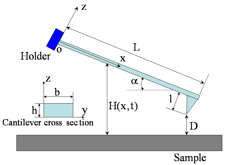 | Figure 1. Schematic diagram of a tip–cantilever system tilted to the sample surface with an angle of  |
 ,ρ Young’s modulus E, tilting angle α composing of a tip with tip length l, vibrating in a liquid with density
  and viscosity
  with speed of V. x is the axis along the cantilever, z vertical axis and y is the lateral axis. H(x,t) is the separation between cantilever and sample in each point of the cantilever in any time. D is the equilibrium separation between tip and the sample. The bending behavior of an AFM cantilever in liquid can be written using beam vibrating formulation by the following ordinary differential equation[13-14]:
 | (1) |
 ), hydrodynamic forces due to the liquid around the cantilever (
 ) and the excitation force (
 ) applied on the cantilever.
2.1. Tip-Sample Interaction
- For interaction of two materials in the presence of a third medium (3), the total force
 to consider is expressed by the extended DLVO theory (XDLVO) proposed by Xu and Yoon[15]:
 | (2) |
 ), the double-layer force (
 ) and a third term (
 ) which represents all other forces such as solvation, structural, hydration, hydrophobic, steric, fluctuation forces, etc[6]. Forces in liquid are expressed as follows:Garcia & Binh have discussed van der Waals forces in atomic force microscopy when operating in liquids and have shown that these forces are almost cancelled out for spherical tips immersed in liquids and seem to be in agreement with recent in situ electrochemistry results[16]. For an interaction between a plane (1) and a spherical object (2), The van der Waals forces are equal to[6]:
 | (3) |
 is the Hamakar constant of the interaction (1-2), D is the distance between (1) and (2) and R is the radius of the spherical object (2). The van der Waals force in a third medium (3) is a function of the Hamakar constant denoted
  estimated by[6]:
 | (4) |
 is approximately given by following contact models: JKR for the lower boundary or DMT for the higher boundary[6]:
 | (5) |
 is the work of adhesion between both objects (1) and (2). In air, the work of adhesion is expressed by[17]:
 | (6) |
 is the interfacial energy and
  &
&  are the surface energy of the objects (1) and (2). It can be approximated by
  [6]:In case of objects submerged in a medium (3), the surface energy, called
  , required to separate two objects (1) and (2) submerged in a medium (3) is given by[17]:
 | (7) |
 where K is the equivalent elastic modulus
 , calculated using the both Poisson’s ratios
  ,
,  and both Young’s modulus
  ,
,  . The parameter
  is defined by
  where
where  . Using λ, the pull-off force can be estimated. For
  the DMT model, for
  the JKR model and for
  the Dugdale model can be used[17].
2.2. Hydrodynamic Forces (Drag and Squeeze Film)
- Due to the motion in liquid two main hydrodynamic forces are produced which are drag and squeeze film forces. Some of the researchers have used simplified models and some scientists have tried to formulate these forces correctly[3, 7, 8]. Some have substituted the quality factor obtained by experimental results in their vibration equation[2]. Many researchers have modeled AFM cantilevers as spherical and cylindrical bodies and results have shown this is an appropriate estimate for many applications of SPM cantilevers. The hydrodynamic force can be considered like this[11]
 | (8) |
 ) in free liquid (coefficient
  ), and a force due to the influence of the sample surface at a finite distance from the cantilever
  : The additional term can be understood by considering the water move between the cantilever and the sample surface. If the cantilever approaches the surface the water must be squeezed out, and the viscous resistance causes a distance dependent force, breaking the movement of the cantilever. The force density can be approximated for low frequencies (less than 17 kHz) by[11]:
 | (9) |
 to the substrate surface, leading to dependency H)x) and therefore to a force profile along the cantilever. For large distances H; the force density
  is nearly constant along the cantilever and for small distances most of the force is concentrated at the end of the cantilever. Researchers have approximated the hydrodynamic force to be in proportion to the cantilever vibration acceleration and velocity as[10-11]:
 | (10) |
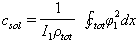
 is the additional mass density and
  is the additional hydrodynamic damping coefficient, due to the fluid. The additional mass density
  may be calculated by[11]
 (11)By representing the beam as a string of beads, Hosaka et al.[21] gave another expression of
  as:
as: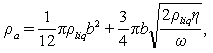 | (12) |
 is the viscosity of the liquid,
  is the vibrating frequency of the cantilever. The additional damping coefficient due to the hydrodynamic effects consists of two parts:
 | (13) |
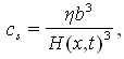
 , is the hydrodynamic damping when the cantilever is vibrating in free liquid (far away from sample surface). When the cantilever is close to the surface, the vibration of the cantilever will squeeze the fluid to flow in and out of the region between the cantilever and sample surface. This produces additional damping and is represented by the second-term in the right hand side of Eq. (13),
  . According to Hosaka et al[21],
  and
and  can be expressed as
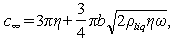 | (14) |
 | (15) |
 | (16) |
 is a constant but
  depends on location and time. The separation of the cantilever tip from the sample is
  | (17) |
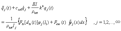
2.3. Governing Equation
- After discussion on tip-sample interaction and hydrodynamic forces, now we write governing equations. For a zero surface electric potential and a non hydrophobic cantilever vibrating in a pure or low salt concentration liquid (hydration force is canceled) using equations (1), (2) and (10) we have:
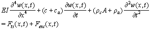 | (18) |
 is the tip-sample interaction which is applied on the cantilever tip.
  | (19) |
 is the repulsive contact force,
  is the intermolecular distance, R is the tip cone radius,
  is the effective elastic modulus given by
  , in which
 ,
,  ,
,  and
and  are the elastic module and Poisson’s ratios of the tip and sample, respectively.
  is the magnetic harmonic excitation force. By setting
  and
and  , and using delta functions Eq. (18) can be written as:
  | (20) |
 is the position of the tip from the beginning of the cantilever and
  is the delta function. The boundary conditions for free vibration of the cantilever are
 | (21) |
 | (22) |
 | (23) |
 | (24) |
 , can be written as the sum of the production of the beam shape functions into a time term for different shape modes[23]:
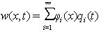 | (25) |
 is the i'th shape mode. In a free vibration we have:
  | (26) |
 | (27) |
 | (28) |
 is:
is: | (29) |
 ,
,  ,
,  and
and  , so coefficients of A, B, C and D can be gained. Also
  . From this equation, many k for different modes can be gained, k for the first mode is
  . By substituting Eq. (25) into Eq. (20) we have:
 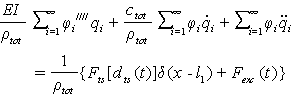 | (30) |
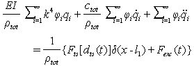 | (31) |
 | (32) |
 and then integrating of the result over the length of the cantilever we have:
 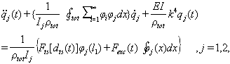 | (33) |
 | (34) |
 As squeeze film damping is dependent on the instantaneous separation,
  should be calculated numerically in the program and then substituted for solving the governing equation in that second. For making less damage to the sample it is better to have a smaller excitation power, so the amplitude of vibration is small and it is possible to account the squeeze film by its equilibrium separation. For simulation we have used a continuous beam model and a forward-time numerical method for solving its hybrid contact due to the nature of contact forces (attractive van der Waals force in the separations larger than intermolecular distance and repulsive force in the separations smaller than intermolecular distance)[24].
3. Simulation and Results
- Using programming in MATLAB, dynamics of tapping-mode AFM in liquid has been investigated. The results of the simulation have been validated with the experiments done by Putman et al[5] and also Rankl et al[11]. Putman et al have used a nitride silicon cantilever in water. Rankl et al have used a rectangular silicon cantilever in buffer (150mM NaCl, 5mM
 , pH=7.5). The parameters of Table 1 have been used for the simulation. In both experiments probe tilting angle (
 ) =15o, Intermolecular distance (
 ) =0.38 nm, Hamakar Constant (A) = 3.19×10⁻¹⁹ J. The elasticity modulus of silicon= 130GPa, its density=2330 Kgm-3, Water density = 1000kg/m3, its viscosity= 8.54×10⁻⁴ kg/(ms), Effective elastic modulus (
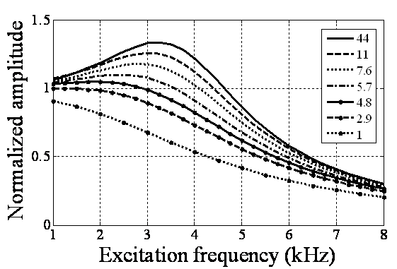
 ) = 10.2GPa and Tip cone radius (R) = 10nmThe TM frequency responses in both air and liquid obtained by Putman et al.[5] shows that the frequency response of the cantilever in liquid is dramatically different from that in air. Due to the additional mass and damping exerted on the cantilever from the surrounding liquid, the resonances are shifted to the left and the vibration amplitudes are quenched[5]. Rankl et al have simply normalized by dividing the curve by the amplitude at zero frequency. The maximum of the amplitude–frequency curves is dramatically shifted towards lower values at decreasing tip–sample separation and vanishes completely below 2.9
  [11].
[11].


 is 18 kHz and with tip length of 5
 is 16 kHz. It means that immersing in liquid dramatically shifts the resonance frequency to smaller values. With tip length of 10
 based on the formula
  the resonance frequency is 18.5810 kHz, but it has a value of 18 kHz in the simulation which shows the effect of additional damping due to vibration in liquid.It can be concluded that the shift in the resonance frequency is more a consequence of the added mass term and less is affected by the reduced quality factor. In the liquid, the cantilever drags along a specific volume of liquid during movements; hence, the cantilever behaves as if its mass were much larger than it really is. Vancura experiment shows this resonance frequency shift too[22].
 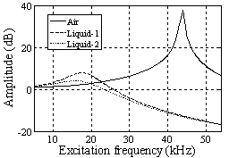 | Figure 2. Simulation of frequency response of TMAFM in liquid by the parameters of Putman et al[5]. In diagram of "Liquid-1" tip length is 10 and the obtained resonance frequency is 18kHz, in diagram of "Liquid-2" the tip length is 5 and the obtained resonance frequency is approximately 16kHz and the obtained resonance frequency is approximately 16kHz |
 | Figure 3. Simulation of frequency response of TMAFM in liquid by the parameters of Rankl et al[11] |
 in equilibrium separation of 25 nm (separation between the tip and sample). As is seen the effect of separation on final amplitude value is great.
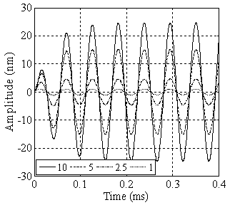 | Figure 4. Simulation of TMAFM in liquid with different tip lengths of 1, 2.5, 5 & 10 in equilibrium separation of 25 nm in equilibrium separation of 25 nm |
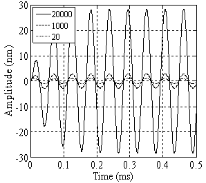 | Figure 5. Simulation of TMAFM in liquid with a tip length of 1and in different separations of 20, 1000 & 20000 nm |
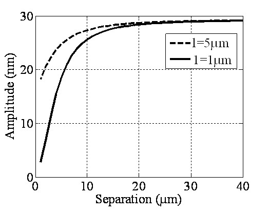 | Figure 6. Simulation of amplitude versus separation diagram for a TMAFM in liquid before contacting the sample surface |
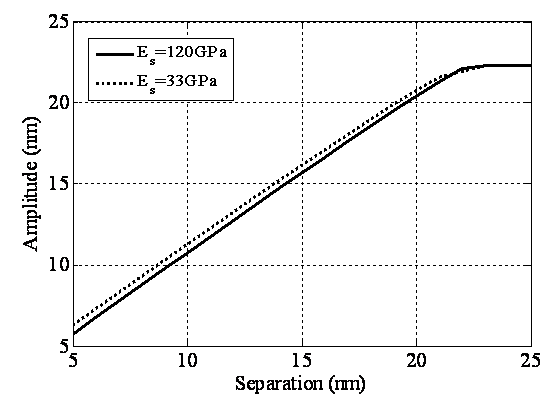 | Figure 7. Simulation of amplitude versus separation in liquid for two different sample elastic modules of 120 & 33GPa |
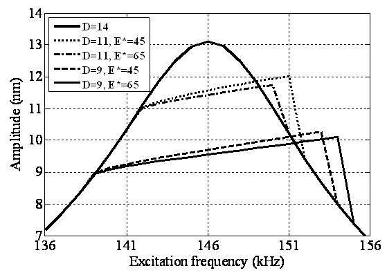 | Figure 8. Simulation of frequency response of TMAFM in liquid for effective elastic modulus of 45 and 65GPa |
4. Conclusions
- We have simulated tapping-mode AFM in liquid and investigated its dynamics. Using forward-time simulation frequency response of the tapping-mode AFM in liquid is given and has been validated with the experimental results done by Putman et al in[5] and Rankl et al[11]. The hydrodynamic effects on AFM cantilevers are addressed by adding additional mass and hydrodynamic damping to the system. The simulation results show a good agreement with the experimental results. The resonance frequency in liquid is so small in comparison to air due to the additional mass (liquid coupled with the cantilever) and also additional damping due to the viscosity of the liquid around. The presence of liquid reduces the cantilever vibration amplitude significantly and shifts the cantilever resonances to smaller values. Reduction of the resonance frequency in liquid is highly related to the additional mass and less related to the damping, Though the effect of the damping is obvious, particularly by reduction of the separation, the resonance frequency has a smaller value; this is because of the squeeze film damping which is highly dependent on the separation. When the cantilever is vibrating close to surface, the hydrodynamic damping due to the fluid squeezed in and out of the region between the cantilever and sample surface becomes significant and needs to be addressed. In vacuum or air the tip amplitude versus separation has a constant value before contacting the sample, and after contacting is reduced linearly, but in liquid just in large separations there is a saturation value and before contacting the sample the amplitude reduces nonlinearly by reduction of the separation. This is because of the squeeze-film damping which is dependent on the separation between the cantilever and sample. Free vibration amplitude is greatly related to the separation between the cantilever and sample and so determination of it should be done carefully. We have also extracted frequency response and amplitude versus diagrams in liquid and compared its treatment with what happens in air.
References
| [1] | N. Hashemi, “Exploring the nonlinear dynamics of tapping mode atomic force microscopy with capillary layer interactions”, Ph.D. Dissertation in Mechanical Engineering, Faculty of the Virginia Polytechnic Institute and State University, 2008. |
| [2] | S. Basak, and A. Ramana, “Dynamics of tapping mode atomic force microscopy in liquids: Theory and experiments”, Applied Physics Letters, vol. 91, 064107, 2007. |
| [3] | R. E. Jones, and D. P. Hart, “Force interactions between substrates and SPM cantilevers immersed in fluids”, Tribology International, vol. 38, pp. 355–361, 2005. |
| [4] | X. Xu, and A. Raman, “Comparative dynamics of magnetically, acoustically and brownian motion driven cantilevers in liquids”, J. of Applied Physics, vol. 102, 034303, 2007. |
| [5] | C. A. J. Putman, K. V. d. Werf, B. G. D. Grooth, N. F. V. Hulst, and J. Greve “Tapping mode atomic force microscopy in liquid”, Applied Physics Letters, vol. 64, no. 18, pp. 2454- 2456 (1994). |
| [6] | M. Gauthier, S. Regnier, P. Rougeot, and N. Chaillet, “Forces analysis for micromanipulations in dry and liquid media”, J. of Micromechatronics, vol. 3, no. 3-4, pp. 389-413, 2006. |
| [7] | J.E. Sader, “Frequency response of cantilever beams immersed in viscous fluids with applications to the atomic force microscope”, J. of Applied Physics, vol. 84, no. 1, pp. 64-76, 1998. |
| [8] | J. W. M. Chon, P. Mulvaney, and J. E. Sader, “Experimental validation of theoretical models for the frequency response of atomic force microscope cantilever beams immersed in fluids”, J. of Applied Physics, vol. 87, no. 8, pp. 3978-3988, 2000. |
| [9] | A. H. Nayfeh, and M. I. Younis, “A new approach to the modeling and simulation of flexible microstructures under the effect of squeeze-film damping”, J. of Micromechanics and Microengineering, vol. 14, pp. 170–181, 2004. |
| [10] | Y. Song, and B. Bhushan, “Simulation of dynamic modes of atomic force microscopy using a 3d finite-element model”, Ultramicroscopy, vol. 106, pp. 847-873, 2006. |
| [11] | Ch. Rankl, V. Pastushenko, F. Kienberger, C. M. Stroh, and P. Hinterdorfer, “Hydrodynamic damping of a magnetically oscillated cantilever close to a surface”, Ultramicroscopy, vol. 100, pp. 301–308, 2004. |
| [12] | M. K. Ghatkesar, Th. Braun, V. Barwich, J. P. Ramseyer, Ch. Gerber, M. Hegner, and H. P. Langc, “Resonating modes of vibrating microcantilevers in liquid'', Applied Physics Letters, vol. 92, pp. 043106, 2008. |
| [13] | M. H. Korayem, and N. Ebrahimi, “Nonlinear dynamics of tapping-mode atomic force microscopy in liquid”, J. of Applied Physics, vol. 109, no. 8, 084301, 2011. |
| [14] | D. J. Gorman, “Free vibration analysis of beams and shafts”, Wiley, New York, 1975. |
| [15] | Zh. Xu, and R. Yoon, “A study of hydrophobic coagulation”, J. Colloid and Interface Science, vol. 134, no. 2, pp. 427-434, 1990. |
| [16] | N. Garcia, and V. T. Binh, “Van der Waals forces in atomic force microscopy operating in liquids: A spherical-tip model”, Physical review B, vol. 46, no. 12, pp. 7946-7948, 1992. |
| [17] | M. Gauthier, D. Heriban, D. Gendreau, S. Regnier, N. Chaillet1, and P. Lutz, “Micro-factory for submerged assembly: interests and architectures”, Proceedings of the 5th International Workshop on Microfactories, IWMF'06, Besancon, France, 2006. |
| [18] | Y. Liang, N. Hilal and P. Langston, and Victor Starov, “Interaction forces between colloidal particles in liquid: Theory and experiment”, Advances in Colloid and Interface Science, vol. 134–135, pp. 151–166, 2007. |
| [19] | P. F. Luckham, “Manipulating forces between surfaces: applications in colloid science and biophysics”, Advances in Colloid and Interface Science, vol. 111, pp. 29–47, 2004. |
| [20] | H. J. Butt, B. Cappella, and M. Kappl, “Force measurements with the atomic force microscope: Technique, interpretation and applications”, Surface Science Reports, vol. 59, pp. 1–152, 2005. |
| [21] | H. Hosaka, K. Itao, and S. Kuroda, “Damping characteristics of beam-shaped micro-oscillators”, Sensors and Actuators A-Physal, vol. 49, pp. 87, 1995. |
| [22] | C. Vancura, I. Dufour, S. M. Heinrich, F. Josse, and A. Hierlemann, “Analysis of resonating microcantilevers operating in a viscous liquid environment”, Sensors and Actuators A, vol. 141, pp. 43–51, 2008. |
| [23] | J. Zhang, N. Xi, G. Li, and Ch. Su ''Atomic force microscopy sensing using multiple modes'', Proc. 2006 IEEE/RSJ, Int. Conf. Intelligent Robots and Systems, Beijing, China, pp. 3928-3933, 2006. |
| [24] | M. H. Korayem, A. Kavousi, and N. Ebrahimi, “Dynamic analysis of tapping-mode AFM considering capillary force interactions”, Scientia Iranica B, vol. 18, no. 1, pp. 121-129, 2011. |