Shadman Sakib1, Ahmed Jawad Kabir2, Md. Shajal Khansur1, Md. Jewel Rana1
1Department of EEE, IUBAT-International University of Business Agriculture and Technology, Dhaka, Bangladesh
2Department of EEE, IUB-Independent University of Bangladesh, Dhaka, Bangladesh
Correspondence to: Shadman Sakib, Department of EEE, IUBAT-International University of Business Agriculture and Technology, Dhaka, Bangladesh.
| Email: |  |
Copyright © 2018 The Author(s). Published by Scientific & Academic Publishing.
This work is licensed under the Creative Commons Attribution International License (CC BY).
http://creativecommons.org/licenses/by/4.0/

Abstract
Solid-state switch mode AC-DC converters having high frequency are used in improving power quality in terms of Power Factor Correction (PFC) at AC mains, reduced Total Harmonic Distortion (THD) of input current also precisely regulated DC output in buck, boost, buck-boost, and multilevel modes with unidirectional and bidirectional power flow. In this paper, analysis and design of a novel single phase AC-DC CUK converter circuit have been proposed where Power Factor Correction (PFC) controller scheme has been used in order to obtain better performance than conventional converters. Closed loop technique is applied to the bridgeless converter in order to achieve low input current, Total Harmonic Distortion (THD) at input AC mains along with near unity power factor. Performance comparison between the open loop and the closed loop of the proposed converter is made without filtering. The problems arise with the open loop is sufficiently minimized by using power factor correction controller. The performance comparison between proposed and conventional CUK AC-DC converter operating in Continuous Conduction Mode (CCM) is made based on circuit simulations using PSIM software.
Keywords:
CUK Converter, PFC, THD, CCM, PWM, PSIM, SEPIC Converter
Cite this paper: Shadman Sakib, Ahmed Jawad Kabir, Md. Shajal Khansur, Md. Jewel Rana, Analysis of a Novel Single Phase AC-DC CUK Converter with Low Input Current, THD to Improve the Overall Power Quality Using PFC, Microelectronics and Solid State Electronics , Vol. 6 No. 1, 2018, pp. 11-16. doi: 10.5923/j.msse.20180601.02.
1. Introduction
Solid-state AC-DC conversion of electric power is extensively used in Adjustable-Speed Drivers (ASDs), Switch-Mode Power Supplies (SMPSs), Uninterrupted Power Supplies (UPSs), battery charging, induction heaters, measurement and testing equipements etc. Conventionally, AC-DC converters which are also known as rectifiers, are developed in two stages using diode and thyristors. They provide controlled and uncontrolled DC power along with unidirectional and bidirectional power flow. However, these two-stage AC-DC converters have power quality problem in terms of injected current harmonics which causes poor power factor and voltage distortion, high crest factor. In view of their increased applications, they are being developed in single-stage to improve power qualiy, reduced number of components and increased efficiency. Several standard have been made due to strict requirements of improved power quality at AC mains. Power quality at AC mains can be improved by using filters in existing installations but the demerit is it increases cost, size, weight and losses in the system. These problems can be eleminated by using input curent shapes, high power factor single-stage converters, Power Factor Correction (PFC) converter etc. In recent years, a variety of DC operating applications have soared in usage and numbers. As traditional AC-DC converters suffer due to low quality input currents, high quality rectifiers are in demand in order to uphold the international regulatory policies. Several methods are in use to improve the overall power quality of the system. Research works are ongoing to bring in new techniques too.Passive filtering improves the THD but it has low input power factor and involves bulky capacitor and inductor [1]. Active filtering requires a smaller sized filter than passive filtering but a DC-DC converter must follow after it [2-6].On the other hand, CUK topology is advantageous than other topologies due to several reasons but very few significant works have been done on this. CUK converter is better than buck-boost converter as it has continuous input-output current and supplies energy to load both when the switch is open and close. CUK circuit has reduced circuit parameters than SEPIC converter, hence the cost is also reduced [7-10].
2. Proposed Converter
2.1. CUK Converter
The proposed converter is shown in figure 1(a).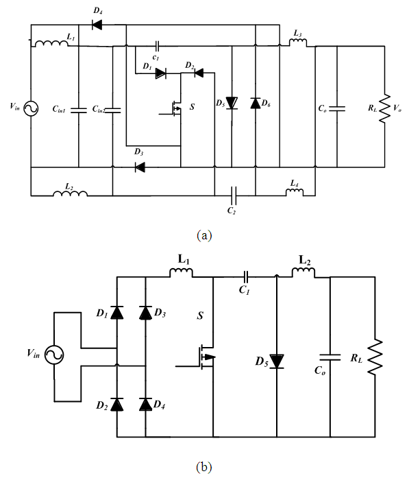 | Figure 1. CUK Converter (a) Proposed (b) Conventional |
3. Principle of Operation
3.1. Single Phase CUK Converter
The proposed CUK converter has four modes of operation: positive and negative cycles each with switch ON and OFF condition, as shown in figure 2.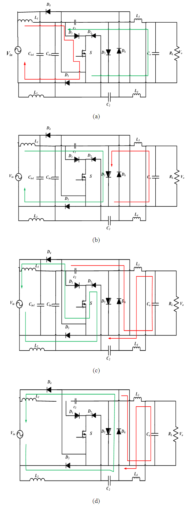 | Figure 2. Four Modes of Operation of Proposed AC-DC CUK Converter: (a) Mode 1: Positive Half Cycle When S is ON (b) Mode 2: Positive Half Cycle When S is OFF (c) Mode 3: Negative Half Cycle When S is ON (d) Mode 4: Negative Half Cycle When S is OFF |
During the positive cycle of the input signal when the switch S is turned ON, current flows in two paths shown in Figure 2(a). The first is from the input, inductor L1, through the switch S, in the second path capacitor C1 and inductor L3 and the output capacitor C0 get charged.In the positive cycle of the input signal when the switch S is OFF, the diode D6 is forward biased. The input capacitors are disconnected, but current continues to flow through the inductors in two paths, as shown in Figure 2(b).During the negative cycle of the input signal when the switch S is turned ON, the diode D5 and D6 are reverse biased. Current flows in two paths, as shown in Figure 2(c).In the negative cycle of the input signal when the switch S is turned OFF and the diode D5 and D6 are forward biased and current continue to flow in two paths shown in Figure 2(d).During both positive and negative cycle of the supply, the energy transferred to the load is uni-directional, thus, AC-DC conversion is achieved.
3.2. Feedback Control to Improve Power Factor
Power quality in an electrical system is determined by its power factor. Open loop operation of conventional AC-DC converters suffers from very low power factor which causes several problems in the overall power system. To resolve this issue, proper feedback controller design which improves the input power factor of the converter is of vital importance.The PFC circuit for the proposed CUK converter along with its control circuit has been shown in Figure 3. The main objective of the PFC circuit is to draw a sinusoidal current, in-phase with the utility voltage. The reference inductor current iL* is of the full-wave rectified form. The requirements on the form and the amplitude of the inductor current, lead to two control loops, the inner current loop, and an outer voltage loop, to provide the required Pulse Width Modulation (PWM) signal to drive the switch of the proposed CUK converter.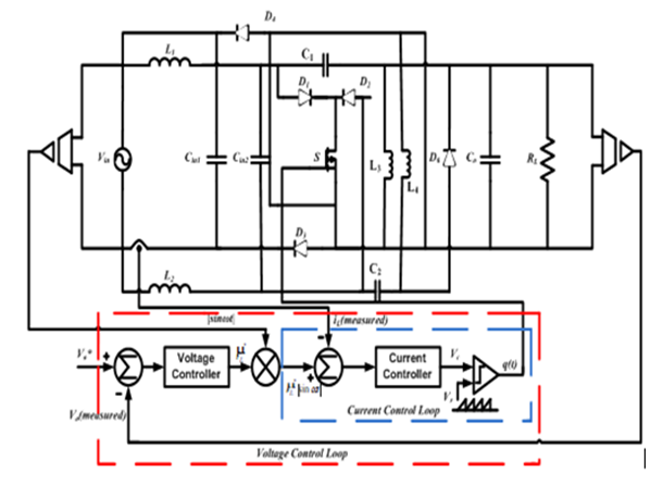 | Figure 3. Proposed converter with feedback control to improve power factor and to reduce THD |
4. Simulation and Results
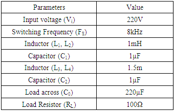
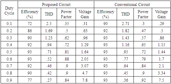
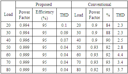
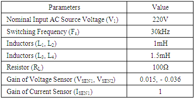
The simulation of the conventional and proposed CUK AC-DC converter was performed using PSIM 9.1 environment. The design parameters used during the simulation are given in Table 1. In Table 2, both conventional and proposed single phase AC-DC CUK converters circuits were subjected to duty cycle variations at a fixed load of 100Ω and constant switching frequency of 8 kHz, whereas in Table 3, the circuit performance under load variation was conducted for both conventional and proposed converter for the switching frequency of 8 KHz at 50% duty cycle and the performance is monitored in terms of percentage efficiency, input power factor, Total Harmonic Distortion (THD) of the input current, and voltage gain. It is evident from the table that the proposed converter shows better performance than the conventional converter with respect to the measured parameters.Table 1. Specification of Design Parameters for Open loop Control
 |
| |
|
Table 2. Performance analysis of proposed CUK converter with duty cycle variation
 |
| |
|
Table 3. Performance analysis of proposed CUK converter with duty cycle variation
 |
| |
|
Comparison for efficiency, input current THD, voltage gain and power factor of the proposed AC-DC CUK converter with conventional converter under duty cycle variation is presented in figure 4.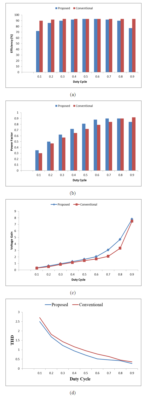 | Figure 4. Graphical Representation of Efficiency (a) Power Factor (b) Voltage Gain (c) and Input Current THD (d) for the Proposed AC-DC CUK Converter with Conventional CUK converter under Duty Cycle Variation |
The proposed circuit is subjected to load variation at a constant duty cycle of 50% and the parameter values are observed subsequently. The power factor increases while the load is varied from 20Ω by a value of 10Ω and reaches almost unity 50Ω onwards. The efficiency maintains a high value throughout the variation while the THD is minimized to a satisfactorily low value. The performance analysis of Table 2 is represented graphically in figure 5.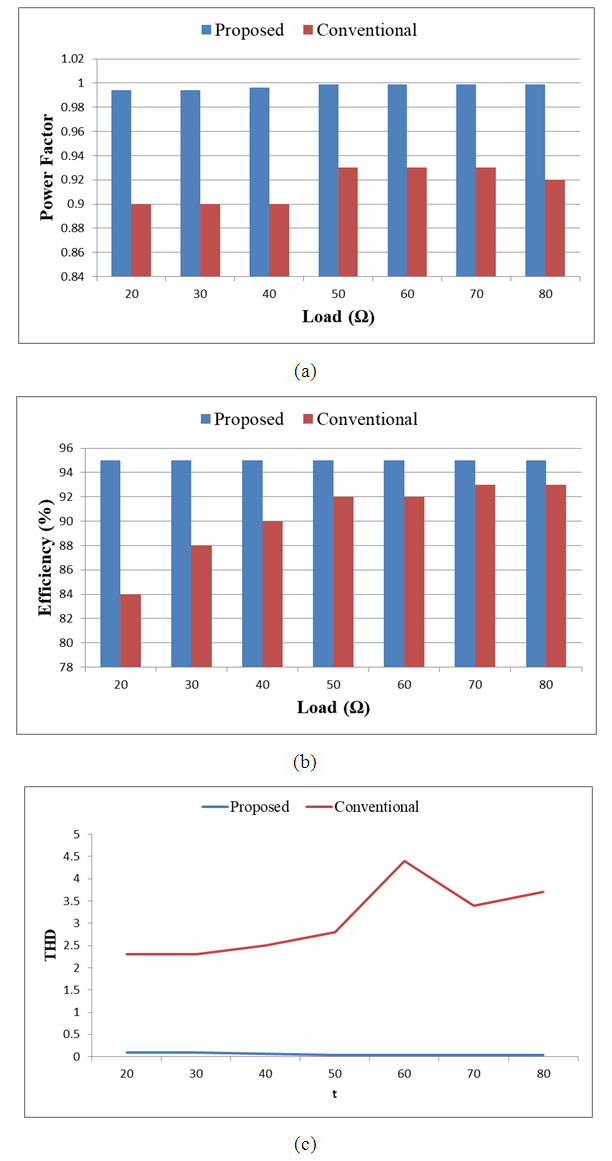 | Figure 5. Graphical Representation of Power Factor (a) Efficiency (b) and Input Current THD (c) for the Proposed AC-DC CUK Converter with Conventional CUK Converter Under Load Variation |
The input-output waveforms of the proposed input switch CUK converter in open loop is given in figure 6.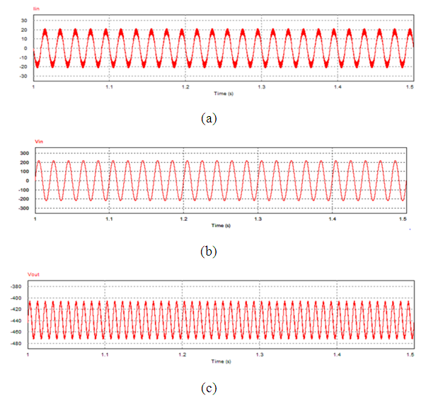 | Figure 6. Input and Output voltage waveforms of proposed CUK converter |
Simulation has been done for the proposed converter with feedback controller which has been shown in Figure 3. The parameters of the circuit are given in Table 4. The PFC controller is designed to obtain an average output voltage of 400 Vdc. The simulation of the designed controller is given in Table 5. The typical input-output waveform of the proposed controller is shown in Figure 7.Table 4. Parameter Table for close loop controller
 |
| |
|
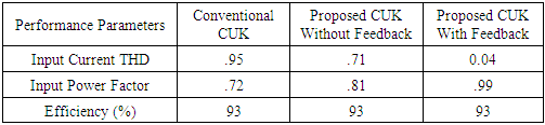
Table 5. Comparison between the conventional and proposed AC-DC converter for both without feedback and with feedback control
 |
| |
|
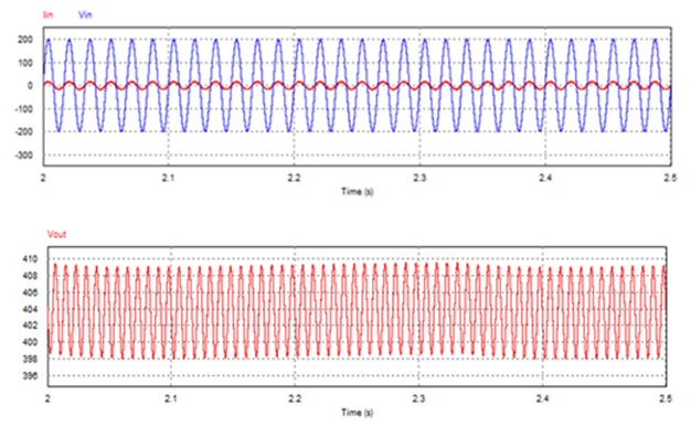 | Figure 7. Input–Output waveforms of the PFC controlled converter of figure 3 |
The performance of the conventional and proposed CUK converter for open loop and closed loop is shown in Table 5. The proposed CUK with feedback controller scheme outperforms both the other converter circuits based on the individual simulation results. The THD of the input ac mains reduces significantly when a PFC is added whereas the efficiency remains the same and the power factor reaches almost unity. All the three mentioned parameters of table 5 show satisfactory values for the proposed CUK converter with feedback controller which is an applicable achievement of the converter circuit in itself. This performance analysis of Table 5 is shown graphically in figure 8.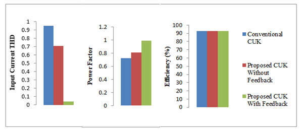 | Figure 8. Comparison among conventional CUK, proposed CUK for open and closed loop for (a) Input Current THD (b) Power factor and (c) Efficiency |
5. Conclusions
In this paper, a novel AC-DC CUK converter circuit has been presented where the PFC controller scheme has been added to obtain a satisfactory result without using the filter circuit in the input side. Many works have done till now show that it is possible to get good results by using filtering in the input side but it does not allow a comprehensive outcome to improve overall power quality such as THD, power factor and efficiency. Instead of using filtering circuit a power factor correction controller has been added with the proposed converter to get the desired results. Also, the input current THD value has been brought within IEEE prescribed limits. Thus this converter circuit holds promise for future which can be practically realized through hardware implementations.
ACKNOWLEDGEMENTS
The authors would like to acknowledge the support and encouragement of the Department of Electrical and Electronics Engineering, IUBAT-International University of Business Agriculture and Technology.
References
| [1] | V. Chellappa, J. Gnanavadivel, and N. S. Kumar, "Power quality improvement techniques in AC-DC Cuk converter," in Emerging Trends in Electrical and Computer Technology (ICETECT), 2011 International Conference on, 2011, pp. 430-435. |
| [2] | B. Singh, B. N. Singh, A. Chandra, K. Al-Haddad, A. Pandey, and D. P. Kothari, "A review of single-phase improved power quality AC-DC converters," IEEE Transactions on industrial electronics, vol. 50, pp. 962-981, 2003. |
| [3] | O. García, J. A. Cobos, R. Prieto, P. Alou, and J. Uceda, "Single phase power factor correction: A survey," IEEE Transactions on Power Electronics, vol. 18, pp. 749-755, 2003. |
| [4] | H. Wei and I. Batarseh, "Comparison of basic converter topologies for power factor correction," in Southeastcon'98. Proceedings. IEEE, 1998, pp. 348-353. |
| [5] | J. C. Salmon, "Techniques for minimizing the input current distortion of current-controlled single-phase boost rectifiers," IEEE Transactions on Power Electronics, vol. 8, pp. 509-520, 1993. |
| [6] | J. W. Kolar and T. Friedli, "The essence of three-phase PFC rectifier systems," in 2011 IEEE 33rd International Telecommunications Energy Conference (INTELEC), 2011, pp. 1-27. |
| [7] | J. Dunia and B. M. Mwinyiwiwa, "Performance comparison between ĆUK and SEPIC Converters for maximum power point tracking using incremental conductance technique in solar power applications," International Journal of Electrical, Computer, Energetic, Electronic and Communication Engineering, vol. 7, pp. 1638-1643, 2013. |
| [8] | J. Betten, "Benefits of a coupled-inductor SEPIC converter," Power Management, 2011. |
| [9] | C. E. Mullett and O. Semiconductor, "An efficient nonisolated DC-DC converter and a review of the more common topologies," Application Note. |
| [10] | T. Jacob and S. Arun, "Maximum Power Point Tracking of hybrid PV and wind energy systems using a new converter topology," in Green Technologies (ICGT), 2012 International Conference on, 2012, pp. 280-287. |

 Abstract
 Reference
 Full-Text PDF
 Full-text HTML