Anjali Taya, Balwinder Singh, Hitesh Pahuja
ACS Division, Center for Development of Advanced Computing, Mohali, India
Correspondence to: Balwinder Singh, ACS Division, Center for Development of Advanced Computing, Mohali, India.
| Email: |  |
Copyright © 2016 Scientific & Academic Publishing. All Rights Reserved.
This work is licensed under the Creative Commons Attribution International License (CC BY).
http://creativecommons.org/licenses/by/4.0/

Abstract
Communication plays an important role in day to day life. The information or data is transmitted through various techniques and line coding is one of the finest techniques for sending data. The selection of these techniques depends on the bandwidth requirement, DC level, bit error rate performance and the inbuilt error detection property. In this line coding techniques whose encoder and decoder have been designed and analyzed are Unipolar RZ, NRZ-I, NRZ-L, Manchester, Differential Manchester, AMI, Pseudoternary, B8ZS, HDB3 coding. Any one of these techniques can be access with the mode of selection. Switching activity is the one of the main factors that is responsible for the dynamic power dissipation. Power consumption by the encoders and decoders is directly proportional to switching activity. To optimize the power of the universal line encoder – decoder, Bus Shift (BS) coding scheme is applied that circularly shifts the data to minimize the transition. Simulation results show the average saving margin of power in universal encoder is 22% while in universal decoder saving margin is 35%.
Keywords:
NRZ-I (Non Return To Zero Invert), NRZ-L (non return to zero level), AMI (alternate mark inversion), Manchester formats, Pseudo ternary encoded format, B8ZS (bipolar eight zero substitution) and HDB3 (high density bipolar zero)
Cite this paper: Anjali Taya, Balwinder Singh, Hitesh Pahuja, Design and Analysis of Low Power Universal Line Encoder & Decoder, Microelectronics and Solid State Electronics , Vol. 5 No. 1, 2016, pp. 7-13. doi: 10.5923/j.msse.20160501.02.
1. Introduction
Digital communication is the transmitting of data over a physical transmission media such as twisted pair, fibre optic link and coaxial cable etc, in the form of digital signals. The process of sending the data one bit at time, sequentially over a communication channel is known as serial communication. The data maintenance is required as it is transmitted through echo chancellors, repeaters and another electronically equipment. Data reconstruction is required time to time for maintained the data integrity. Transmission coding (also known as line coding) operation used in high speed systems for digital transmission of telephony and television. The propose modifications into the signal which ease synchronization, error detection etc [10]. Converting a sequence of 1’s and 0’s to a time domain signal suitable for communication over a channel is known as line coding. The main goal of the line code is to minimize noise effects on the information existing on the channel by finding the suitable form of the transmitted information signal. The primary factors should be considered when choosing the line code: self synchronization, transmission power, power spectral density, low probability of error and transparency etc. Present applications of line codes are astronomic in data communication networks and storage of information systems [5].
2. Related Works
Mohammed Alamgir et. al [1] purposed bus shift (BS) coding scheme that circularly shifts the data to minimize transition. Power saving of the bus invert is poor in average cases while BS scheme better in both maximum and average cases of power save 14% for a 32 bit bus.Shankaranarayana Bhat et. al [3] purposed a technique for bus encoding which reduce number of transition on data bus, acts better than the current methods such as bus invert coding and shift invert coding for random data in terms of switching activity. Here reduction in switching activity irrespective of bus width and more power efficient.Amrinder Kaur et. al [5] describes the implementation of various line encoders and decoders using VERILOG on a single chip. Anjali.v et. al [6] in this the implementation of Manchester encoder and decoder circuit along with irrational detection and clock recovery unit (CRU) using HDL. This encoding technique is broadly used in fields like biomedical applications, satellite communication etc.Wei Dang [4] purposed the rules based on the HDB3 encoder and decoder. For the detection of four zero’s sequence in source information, there are four modules in encoder. For the generator of “V” and generator of “B”, obeying the alternate mark inversion (AMI) rule. Simulated output of HDB3 encoder & decoder proved that results are identical with theory analysis.Balwinder singh et. al [13] In this paper read/write cycles are required for memory testing. The result shows the power reduction of 30% and 74.8% in data bus and address buses encoding schemes.
3. Line Coding Techniques
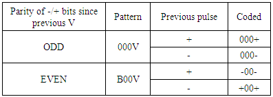
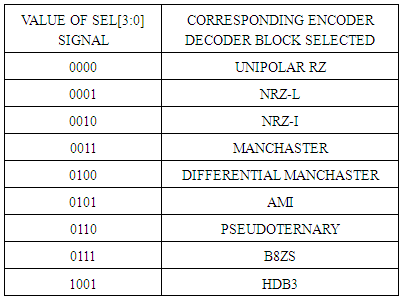
Line coding techniques can be widely divided into following different classes:Unipolar RZ: In this encoded format binary 1 is represented by 01 for first half interval and it return to 00 for second half interval. Binary 0 is represented by 00 for both intervals.Unipolar NRZ-I: In this encoded format binary 1 is represented by high level and for next bit position it represented by low level. Binary 1 is alternating bit by bit. Binary 0 represented by same level as binary 1. Unipolar NRZ-L: In this encoded format binary 1 is represented by low level and for binary 0 is represented by high level.Manchester Encoded: In this binary 1 is represented by 01 (high positive level) for first half bit interval and 11 (low negative level) for second half bit interval. Binary 0 is represented by 11 (low negative level) for first half bit interval and 01 (high positive level) for second half bit interval [3].Differential Manchester Encoded: In this binary 1 is represented by 01 (high positive level) for first half and 11 (low negative level) for second half of bit interval. For next bit 1 is represented by 11 (low negative level) first half and 01 (high positive level) second half. Binary 1 is alternating bit by bit. Binary 0 is represented by same level as binary 1.AMI (alternate mark inversion): In this encoded format bit 1 is represented by 01 and 11 alternatively for bit duration while bit 0 is represented by 00 for whole bit interval.Pseudo ternary Encoded: In this encoded format bit 1 is represented by 00 for whole bit interval while bit 0 is represented by 01 and 11 alternatively for bit duration.B8ZS (binary eight zero sequence): In this encoded format each string of eight zeros are represented by 000+-0+- if it comes after positive pulse while 000-+0+- if it comes after negative pulse.HDB3 (High density bipolar three): In this encoded format each string of four zeros are represented according to the odd and even parities define in table 1 [12].Table 1. HDB3 pattern
 |
| |
|
3.1. Encoding Algorithms
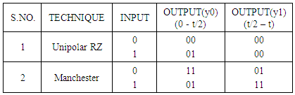
The signed binary characters are used to implement the design. By using that, zero voltage level represented by 00, while high (positive) voltage level represented by 01 and low voltage (negative) level is represented by 11. Therefore +1 =00-1 = 110 = 00The algorithm for Manchester and Unipolar RZ encoding technique is given in table 2. The differential Manchester algorithm is given in table 3. The truth table for AMI encoding technique is shown in table 4, and for Pseudoternary encoding is shown in table 5.Table 2. Algorithms
 |
| |
|
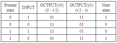
Table 3. Differential Manchester
 |
| |
|
Table 4. AMI Truth table
 |
| |
|
Table 5. Pseudoternary truth table
 |
| |
|
3.2. Decoding Algorithm
The decoding rules for the line coding techniques are reverse from the encoding algorithms. The rules for decoding the line coded scheme differ for each technique defined below.Unipolar RZ: IN this decoding format if input is 01 then it decoded the signal as 1 and if observe 00 then it decoded signal as 0.NRZ-I: The conversion from the previous voltage level would be decoded as bit 1 while no shift or no conversion would be decoded as bit 0.NRZ-L: In this high voltage level decoded as bit 0 and low voltage level decoded as bit 1.Manchester decoded: In this at the positive edge if the input is 01 then it would be decode as bit 1 and if it detect 11 then it would be decode as bit 0.Differential Manchester decoded: In this if there is transition occur in the input level from the previous bit then it decoded as bit 0 and if there is no transition occur then it decoded as bit 1.AMI decoded format: In this if it detect either 01 or 11 then it would be decode as bit 1 while if it detect 00 then it would be decode as bit 0.Pseudoternary decoded format: In this if 00 is detected then it would be the decode as bit 1 while if it detect either 01 or 11 then it would be decode as bit 0.B8ZS decoded format: In this if the sequence of 000+-0+- or 000-+0+- is detect it would be decode as sequence of eight zeros. HDB3 decoded format: In this format according to the odd and even parities, pattern generated 000v or b00v it would be decode as sequence of four zeros [4].
4. Bus Shift Encoding Technique
In this shift the data word on a bus to get minimum transition and also it reduce the power. For simplicity, we use only right shift but in circular manner. Given presentdata or nextdata, to determine how many bits of nextdata to shift, do the following:1. For j = 1 to m, shift nextdata to right by j-bit and determine the hamming distance between the presentdata and shifted word.2. Let us assume HD(min) is the number of bits that result in minimum hamming distance.3. Shift the nextdata by HD(min) bits and send the shifted word [1].Example of bus shiftOn a 10 bit bus, let us assume presentdata = 1011001001 and the nextdata = 0011011001; here HD(min) between the words is 3. The Bus shift will find that on the right shifted nextdata by 7 bits to get 1011001001 results in zero hamming distance as compare to presentdata [1]. After that power reduced on the bus, is calculated by applying all the coding techniques [3]. To determine the power dissipation is given by: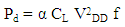 | (1) |
α = Switching activityVDD = Supply Voltagef = FrequencyCL = load capacitance
5. Universal Line Encoder & Decoder with Low Power Technique
In the universal line encoder-decoder by using structural style modelling we have integrated all the 9 line coding technique together. In this we use the four bit select line for the selection of 9 line coding technique from 0000 to 1001. Given user data gets converted in the bit format to the desired line coding and additionally at the receiver end, converted back line coding signal to bit format [10].Table 6. Block selection table
 |
| |
|
In this universal line encoder & decoder by using the bus shift coding technique power has been reduced. This technique based on the hamming distance between the presentdata and nextdata. In the universal encoding method least number of transitions is used to encode the data and transmit it over the bus. The universal decoder has ability to coded back signal to bit format at receiver end by using least transitions. The optimized universal encoder & decoder has low power, high speed, low complexity, and useful for all coding techniques.
6. Result and Discussion
ISIM simulator is used for the analysis of universal line Encoder & Decoder as shown in Figs 1-3. In this sel [3:0] pin is used to change line coding technique.Figure 1 shows the results for universal line encoder when the sel[3:0] = 0000, due to this value Unipolar RZ is enabled and get the results at the signal z[1:0]. In the Fig.2 values of signal sel[3:0] = 0110 change and get the output of Pseudoternary encoder block.Figure 3 shows the results of universal line decoder when the sel[3:0] = 0001, due to this value NRZ-I is enabled and get the results at the output signal z[1:0]. Similarly by changing the values of the sel[3:0] signal, then the selected blocks also change the corresponding values on sel[3:0] signal and get outputs at selected blocks on z[1:0] signal.The power analysis of optimized Universal line encoder & decoder by compared with the conventional Universal line encoder & decoder. Performance analysis shows the power saving margin of 22% in average cases of universal line encoder while the saving margin of 35% in average cases of universal line decoder by using bus shift coding technique.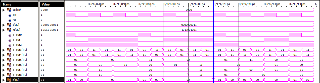 | Figure 1. Universal encoder when sel[3:0] = 0000 |
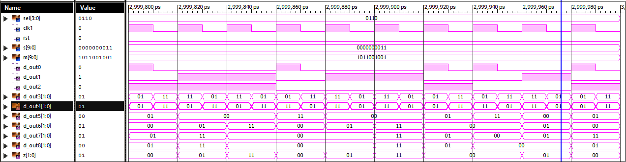 | Figure 2. Universal encoder when sel[3:0] = 0110 |
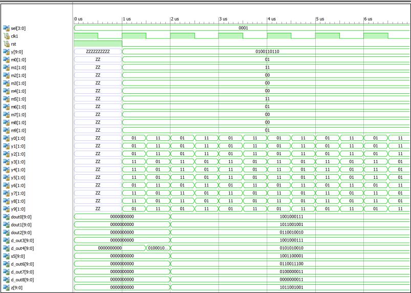 | Figure 3. Universal decoder when sel[3:0] = 0001 |
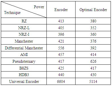
In the Figure 4 given below, this graph shows the power comparison between the different line coding techniques of encoders and optimized encoders as given in Table 7. 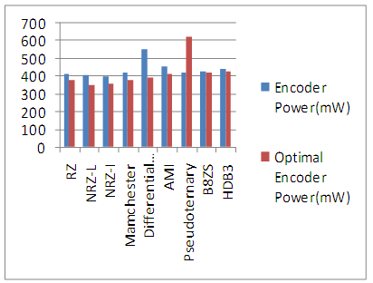 | Figure 4. Encoder Power (mw) graph |
Table 7. Encoder Power analysis
 |
| |
|
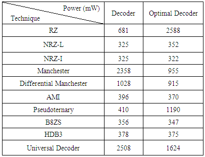
In Figure 5 this graph shows the power comparison between the various line coding techniques of decoders and optimized decoders by using the Table 8.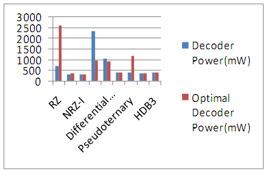 | Figure 5. Decoder Power (mw) graph |
Table 8. Decoder Power analysis
 |
| |
|
The final result of power is shown by the universal encoder & decoder as shown in figure 6, where we analyze that power is saved 22-33% by using the bus shift technique.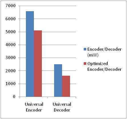 | Figure 6. Universal encoder & decoder graph |
Delay: For the both universal encoder and decoder speed grade is -3 and minimum period required or delay for the encoder is 2.556ns and for universal decoder 1.129 ns. Optimized universal encoder and decoder has better minimum period requirement as compare to conventional encoder decoder. Speed grade is -3 and the delay for the optimized encoder is 2.153ns and for the optimized decoder is 0.766ns.
7. Conclusions
In this research work, universal line encoder & decoder has been designed and analyzed by using the various line coding techniques. After that binary shift coding technique is used to reduce dynamic power dissipation in data bus by circularly shifts the bits to minimize the transition. Optimized universal encoder & decoder were compared with the conventional encoder & decoder, which shows the power saving margin of 22% in case of encoder while 35% in case of decoder. The design has low complexity, high speed, low power and efficient for all the encoding and decoding schemes.
References
| [1] | M. Alamgir, I. I. Basith, T. Supon and R. Rashidzadeh, "Improved bus-shift coding for low-power I/O," 2015 IEEE International Symposium on Circuits and Systems (ISCAS), Lisbon, 2015, pp. 2940-2943. |
| [2] | Abdelrahman H. Elsayed, Ramy N. Tadros, Maged Ghonemia, yeheaIsmail “Low-Power All-Digital Manchester-Encoding- Based High-Speed Transceiver for On-Chip Networks”, IEEE Conference Publications, Pages: 2752 - 2755, 2014. |
| [3] | Shankaranarayana Bhat M and D. Yogitha Jahnavi “Universal rotate invert bus encoding for low power VLSI”, International Journal of VLSI design & Communication Systems (VLSICS) Vol.3, No.4, pp.97-109, August 2012. |
| [4] | Wei Dang, "Implement of HDB3 coder in base-band system," in Consumer Electronics, Communications and Networks (CECNet), 2012 2nd International Conference, pp.3273-3274, 21-23 April 2012. |
| [5] | Amrinder Kaur, Mandeep Singh, Balwinder Singh “VHDL Implementation of Universal Encoder for communication”, ISP Journal of Electronic Engineering, Vol.1, Issue.2, ISSN 2250-0537(online), pp. (37-41). Dec 2011. |
| [6] | Anjali. V, P. Satishkumar, "Manchester Encoder and Decoder with Clock Recovery Unit and Invalid Detector”, ISSN 2222-1719 (Paper) ISSN 2222-2863 (Online) Vol.6, No.2, 2015. |
| [7] | Sridhar, K.P.; Agalya, R.; Narmatha, D.; Vignesh, B.; Saravanan, S., "Test data compression using Hamming Encoder and Decoder for system on chip (SOC) testing," in Circuit, Power and Computing Technologies (ICCPCT), 2014 International Conference, pp.1094-1098, 20-21 March 2014. |
| [8] | Mircea R. Stan, Wayne P. Burleson, “Bus-invert coding for low power I/O”, IEEE transactions on VLSI systems, vol. 3, no. I, March 1995. |
| [9] | C.nithya, d.kowsalya devi, “Efficient and high speed VLSI modelling of fm0/manchester encoding using sols technique and clock gating technique for dedicated short range communication applications”, International Journal for science and Advance Research In Technology(IJSART) vol. 1 Issue 6, pp.2395-1052, June 2015. |
| [10] | Prabhat Kumar Mishra, Sahaj Saxena, “A Novel Approach for VHDL Implementation of Universal Line encoder for Communication”, International Journal of Electronics Engineering, 2(2), pp. 339-340, 2010. |
| [11] | Suchitra Suresh, “VHDL implementation of Manchester encoder and Decoder”, International Journal of Electrical, Electronics and Data Communication, vol-1, ISSN 2320-2084, April 2013. |
| [12] | Vivek Singh, Brijesh Mishra, “FPGA implementation of various lines coding technique for efficient transmission of digital data in communication”, International Journal of Research in Engineering and Technology, e-ISSN: 2319-1163 pISSN: 2321-7308, vol. 03, April 2014. |
| [13] | Balwinder Singh, Arun Khoshla, S. Bindra. Narang “Low power bus Encoding Techniques for memory testing”, Microelectronics and solid state Electronics 2(3), pp. 45-51, 2013S. M. Metev and V. P. Veiko, Laser Assisted Microtechnology, 2nd ed., R. M. Osgood, Jr., Ed. Berlin, Germany: Springer-Verlag, 1998. |

 Abstract
 Reference
 Full-Text PDF
 Full-text HTML