-
Paper Information
- Paper Submission
-
Journal Information
- About This Journal
- Editorial Board
- Current Issue
- Archive
- Author Guidelines
- Contact Us
Microelectronics and Solid State Electronics
p-ISSN: 2324-643X e-ISSN: 2324-6456
2016; 5(1): 1-6
doi:10.5923/j.msse.20160501.01

Microcantilever Based RF MEMS Switch for Wireless Communication
 Abstract
 Reference
 Full-Text PDF
 Full-text HTML
Shaik Jani Basha 1, M. Hanu Sai Krishna 1, Ch Anish Praharsha 1, P. Harish Babu 1, V. Karthikeya 1, Y. Srinivas 2, D. Rajya Lakshmi 3, Srinivasa Rao K. 1
1Department of ECE, K L University, Greenfields, Vaddeswaram, Guntur District, A.P., India
2Department of IT, GITAM University, Hyderabad, Telangana, India
3Department of CSE, University of Engineering College JNTUK, Vijayanagaram, A.P., India
Correspondence to: Shaik Jani Basha , Department of ECE, K L University, Greenfields, Vaddeswaram, Guntur District, A.P., India.
| Email: |  |
Copyright © 2016 Scientific & Academic Publishing. All Rights Reserved.
This work is licensed under the Creative Commons Attribution International License (CC BY).
http://creativecommons.org/licenses/by/4.0/

MEMS (Microelectronic mechanical systems) enjoy wide range of applications in Medical, Biological and Communication engineering. Designing the Micro sensors and Microelectronic elements with high reliability is of high prominent in communication engineering. RF MEMS Switches with high reliability, low activation voltage, low insertion loss and high isolation are needed for high performance applications of Microwave and communication engineering. This paper mainly engrossed on improving performance and reliability of RF MEMS Switch. The proposed design consist of mechanical structure with microcantilever beam and capacitive contact type. RF MEMS Switch is designed and simulated in COMSOL Multiphysics, Finite Element Analysis (FEM) Tool. The Switch wants to connect or disconnect RF (Radio Frequency) Transmission line or any other RF microcircuitary network. The switching operation is based on electrostatic force induced between two electrodes of the design. This induced electrostatic force helps the surface of the cantilever beam to do deflections and the circuit will be closed so that RF line Transmission occurs. Deflection of the microcantilever beam depends upon the electrostatic force developed on the electrodes. This electrostatic force produced be influenced by the applied voltage across the electrode which needs to be smaller for high performance and high reliability criteria.
Keywords: RF, MEMS, COMSOL, and Microcantilever
Cite this paper: Shaik Jani Basha , M. Hanu Sai Krishna , Ch Anish Praharsha , P. Harish Babu , V. Karthikeya , Y. Srinivas , D. Rajya Lakshmi , Srinivasa Rao K. , Microcantilever Based RF MEMS Switch for Wireless Communication, Microelectronics and Solid State Electronics , Vol. 5 No. 1, 2016, pp. 1-6. doi: 10.5923/j.msse.20160501.01.
Article Outline
1. Introduction
- MEMS is an acronym for micro electro mechanical systems. Electronic components desires to have low size with high performance aspects. MEMS has its impact over all electronic devices decreasing the size of the device along with improving the reliability of the device. A normal traditional switch like a pin diode or FET derives major disadvantages like high usage of power, low reliabily and high cost for fabrication [2]. RF MEMS Switch is newly evolving component in electronics with low size and low fabrication cost with improved switching parameters. RF MEMS Switches are of many types. The classification of RF MEMS switches is given in Figure 2. Depending on the type of mechanism, we have Cantilever beam, Fixed-Fixed beam and Diaphragm. Depending upon type of actuation there are electrostatic and electro thermal type of RF MEMS Switches. The contact type can be metal-to-metal (resistive) contact or capacitive contact. The RF MEMS Switches can be used in Series, Shunt or Series & shunt configurations also [2]. This paper proposed a design which is implemented using microcantilever mechanism with electrostatic actuation principle and capacitive contact.Capacitance ratio between the up-state position in open circuit condition and downstate position in short circuit position gives the capacitive contact. This value is basically 80-160 depending upon the design [1]. The downstate capacitance is normally 2-3pF, which is suitable for 8-100 GHz application. Whereas metal to metal contact switches will have small upstate capacitance in open circuit can operate from 0.01 to 40 GHz [1] [3]. This proposed RF MEMS Switch is basically for high frequency applications for RF transmission so, this design is developed with capacitive contact type rather than traditional metal-to-metal (Resistive) contact type. Recent development is been carried in the field of MEMS about improving the performance of RF MEMS Switches by Zlatoljub D. Milosavljeic, Gabriel M Rebeiz and A. Q. Liu (Ai-Qun Liu) from Singapore.
2. Microcantilever Based Switch
- Microcantilever deflections depends not only on the electrostatic force but also on mechanically induced forces. The main parts of RF MEMS Switch consists of bottom electrode, top electrode, microcantilever beam, anchor, RF Line for RF transmission and a pull down electrode. When a defined amount of actuation voltage (4V) is applied to the microcantilever, certain amount of electrostatic force is generated.This electrostatic force will pull the microcantilever from the arm of the anchor to do deflections and completes the path for RF signal at down-state. Thus this switch is closed. The short circuit acquired between the two terminals of RF transmission line has made the RF signal pass through and gets transmitted. The basic structure of microcantilever beam is shown in Figure 1.
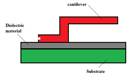 | Figure 1. Basic structure of microcantilever beam |
3. Design of MEMS Switch
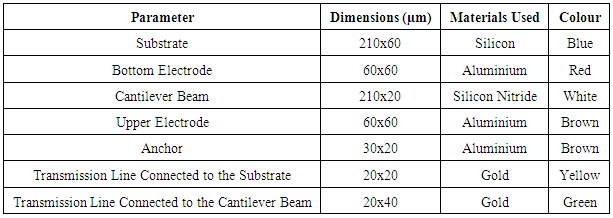
- The RF MEMS Switch is designed using COMSOL Multiphysics. The design parameters are provided in the table 1 [2]. The materials proposed for the RF MEMS switch will give high performance and contact type give high sensitivity to the device [4].
|
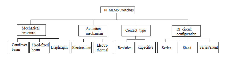 | Figure 2. Different types of RF MEMS Switches |
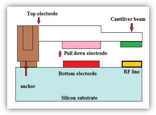 | Figure 3. Side view of RF MEMS switch in open condition |
 | Figure 4. RF MEMS Switch in OFF state |
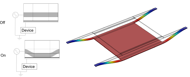 | Figure 5. RF MEMS Switch in ON state |
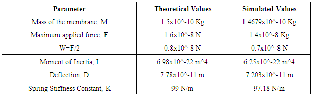
4. Parameter Study
- RF MEMS Switch consists of two different parameter analysis: the actuation (mechanical) section and the electrical section. This paper deals with both the electrical and mechanical parameters as well. The mechanical parameters calculated from this design will be (a) Mass of the membrane (M), Maximum applied Force (F), Moment of Inertia (I), Deflection (D), Spring Stiffness Constant (K). The Table 2 gives the mechanical parameters theoretical and simulated values as well.
|
5. RF MEMS Switch Working
- A Typical RF MEMS switch needs actuation voltage so, a voltage level of 5V is applied to the upper electrode of the MEMS switch and the lower electrode is grounded. The anchor and the substrate are fixed at one end while the other end of the cantilever is free to move. When certain amount of actuation voltage is applied to one end of the cantilever a force so called electrostatic force is generated at the free end of the cantilever beam. This electrostatic force will make the micro cantilever beam to oscillate and will complete the RF line which is placed at the free end of the micro cantilever beam. The switch remains in OFF state till the 4V applied voltage and will be ON at 4V as shown in figure 5. So, the actuation voltage for the proposed design is 4V which is the reduced voltage for a typical RF MEMS Switch. This microcantilever MEMS switch can be fabricated and the array of such switches are packaged along with the micro battery will reduce the manufacturing cost of the device. The block diagram of the RF MEMS switch is given in Figure 6. The spring stiffness constant of the RF MEMS Switch designed is 97.18 N/m which is improved feature of the Switch.
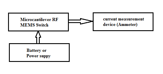 | Figure 6. Block Diagram of RF MEMS switch |
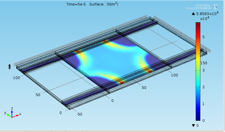
6. Simulation Results
- The proposed RF MEMS switch designed in COMSOL Multiphysics with the selected parameters. The simulated results are graphically shown below. The simulated results are plotted in frequency and time domain as well. Figure 9 shows the low Reference Impedance in frequency domain which is improved parameter of the propose RF MEMS Switch. The Maximum applied force is 1.4x10^-8 Kg obtained from simulation. Whereas the theoretical value is 1.6x10^-8 N which implies the simulated results are 97% accurate to theoretical values. Moment of Inertia obtained from simulation is about 6.25x10^-22 m^4. The deflection of microcantilever is 7.203x10^-11m.
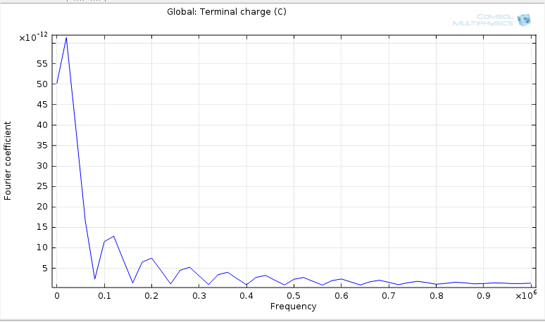 | Figure 7. Terminal Charge in Frequency domain |
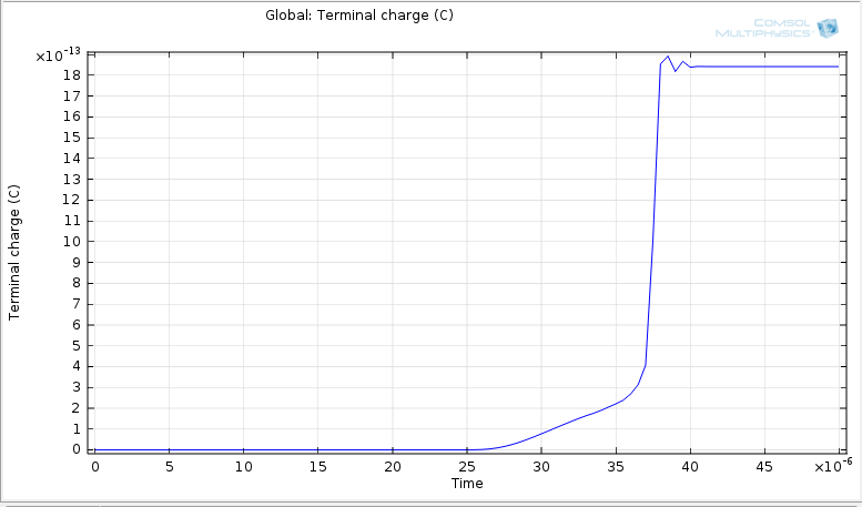 | Figure 8. Terminal charge in Time domain |
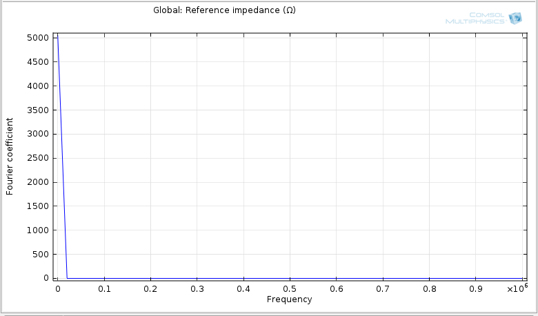 | Figure 9. Reference Impedance in Frequency domain |
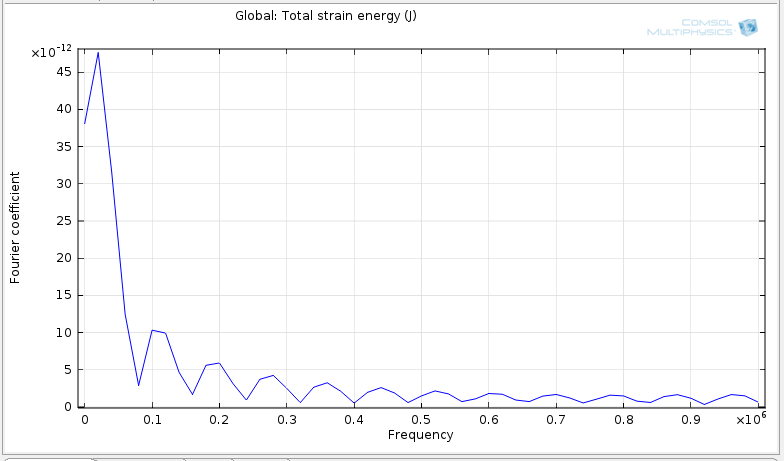 | Figure 10. Total strain in Frequency domain |
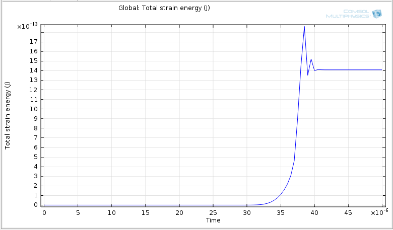 | Figure 11. Total strain energy in time domain |
7. Conclusions
- From the results obtained the switch activated with in less time and with low actuation voltage is series of these switches are arranged in shunt/series the reliability and performance of the device will be high. This device needs very low actuation voltage of 4V and has high spring stiffness constant of 97.18N/m. So, this RF MEMS switch with low actuation voltage and high spring constant can be used in many RF applications.In order to achieve all these characteristics and improved parameters the RF MEMS switch needs to fabricate. Micro scale battery is needed for fabrication of this device. This battery and Switch array can be packed in a small chip as shown in Figure 6. This miniatured device can be of 1cm×1cm size. This fabrication can be done through three basic fabrication processes namely surface micromachining, bulk micromachining and LIGA (Lithographic Galvano forming abforming) process. If manufacturer fabricates thousands of devices, then total cost of fabrication and packaging will be very low.
ACKNOWLEDGEMENTS
- The Authors would like to thank National MEMS design center (NMDC) supported by NPMASS, IISc, Bangalore.