K. K. Singh1, Hardeep Kumar1, Anuj Kumar2, Gaurav Chaudhary1
1Department of Electrical and Electronics Engineering, BITS Pilani, Dubai Campus, Dubai, U.A.E.
2Department of Mechanical Engineering, BITS Pilani, Dubai Campus, Dubai, U.A.E.
Correspondence to: Hardeep Kumar, Department of Electrical and Electronics Engineering, BITS Pilani, Dubai Campus, Dubai, U.A.E..
| Email: |  |
Copyright © 2014 Scientific & Academic Publishing. All Rights Reserved.
Abstract
In the recent past, there have been a number of researches on integrated gas sensors tailored for various applications such as disease detection, pollution monitoring and many more. Most of the previous designs were based on the “micro-array” type. However, this could significantly consume huge space on the substrate. With an interest of providing a cost effective solution, a novel micro/nano engineered gas sensing chamber has been designed. In this paper, the mathematical model of the gas detection mechanism for the evaluation of the system performance has been discussed. The model has been optimized for high sensitivity operation and the optimal velocity of the gas flow in the chamber has been found to be 2e-5 m/s for NO2 and H2 in air of concentrations 100 ppm and 2000 ppm respectively, at 50°C.
Keywords:
MEMS, Gas Sensor, MHP, Gas Chamber, COMSOL
Cite this paper: K. K. Singh, Hardeep Kumar, Anuj Kumar, Gaurav Chaudhary, Analysis and Simulation of MEMS Based Multiple Gases Detection System Using COMSOL, Microelectronics and Solid State Electronics , Vol. 3 No. 1, 2014, pp. 15-19. doi: 10.5923/j.msse.20140301.03.
1. Introduction
The idea of “gas sensors” has been conceived in the early 18th century. Catalytic combustion (LEL) sensor is the first type of gas sensor developed [1]. The mechanism of LEL sensor is based on the fact that the oxidizing gases increase the resistance of the hot wire filament. In 1925, Dr. Uzumi Doi has invented a new interference based technology for the gas detection at the Institute of Physical and Chemical Research, Japan [2]. This was very useful in the monitoring of the explosion of methane vapours from the oil tankers. This follows the method of light diffraction in air. In early 80s, MDA pioneered toxic detection using paper tape technologies [3].The concept of miniaturization in the field of “gas sensors” has originated in the year 2000 through the invention of watch type portable gas monitor. Since this invention, many researchers in this field focused extensively in bringing out miniaturized gas sensor products [4-6]. Micro-electromechanical System (MEMS) technology has aided these researchers in their objective. In most of the initial attempts, there were inextricable issues due to the cross-sensitivity towards the background gases. Hence, the signal to noise ratio (SNR) was poor. Later researches were concentrated on an effective sensing of gases with maximal SNR [7].With the blooming of chemical industries, oil refineries, etc. in this modern world, there is a potential danger due to multiple poisonous gases exiting out. This calls for an integrated monitoring of the gases. The similar situation is associated with the chemical/biological research laboratories [8-10]. Further, an integrated gas sensor is an unavoidable component for the world’s future smart infrastructure initiative.Gases are linked to all forms of life and their odors tremendously influence the perception of our environment. The human nose serves as the highly advanced sensing instrument that is able to differentiate between hundreds of smells. But it cannot detect absolute gas concentrations or sense odorless gas. Various sensing technologies are often used in fire alarms and smoke detectors including heat detectors, photoelectric detectors (which detect smoke), and ionization detectors (which are activated by the airborne particles of combustion).In addition to the above applications, an integrated gas sensor has also influenced the healthcare industry in a positive way. In the healthcare sector, Gas sensors are referred by its popular jargons: “an electronic nose” or “breath analyzer”. They examine odors from the body or from the human breath and serve to identify possible problems. “For example, odors in the breath can be indicative of gastrointestinal problems, infections, infected wounds and tissues emit distinctive odors that can be used for diagnosis, and odors coming from body fluids can indicate liver and bladder problems [11]. The previous designs of MEMS based integrated gas sensors were based on “micro-array” type [3]. However, this consumes a lot of space on the substrate. This way, the cost of manufacturing/fabrication increases. In this paper, we present an alternative solution for the cost-effective production of integrated gas sensors. The design employed is based on tube geometry with nano-engineered pores [15, 16].The paper is structured in 3 sub-sections. The first sub-section deals with the description of physical architecture of the gas sensor system. The second sub-section deals with the mathematical modelling related to the detection process. The last sub-section deals with the optimized solution of the mathematical model [12-14].
2. Physical Architecture of Gas Sensor
The gas detection chamber is tube shaped with an alternative assembly of electrically conductive and non-conductive micro-rings as shown in Figure 1. The electrically conductive micro-discs are the gas sensitive elements in the chamber. These are pre-heated to the requisite temperatures for optimal detection. The heating is accomplished using Micro-Hot Plates. The changes in the resistance of conductive micro-discs provide information about the concentration of gas flowing through the chamber. For the proof of concept, the suspension of NO2 and H2 gases in air is considered and the ‘m’ and ‘n’ electrically conductive micro-discs respectively, are tailored for their detection. The non-conductive micro-discs are used for the electrical isolation of two conductive micro-discs.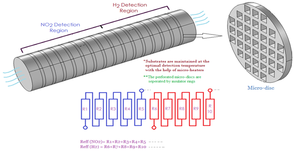 | Figure 1. Architecture of the Gas sensor system |
3. Mathematical Modeling and Numerical Simulation
3.1. Micro Hotplate Design
Micro hotplate (MHP) is one of the components in sensing system. It is placed adjacent to the sensing layer. There is a need to elevate the temperature of the sensing layer for the capture of gas analytes. This can be made possible by using micro hotplate. A best fitted circular type porous MHP has been designed.The electrical field distribution, E, across the heater structure is determined by the equation, | (1) |
Where, ∇V is the potential difference across the micro heater. The boundary condition for this equation is defined by the applied constant potential at both heater contacts, Which are defined at the base contacts of the anchors of the beam. The physics of Joule’ heating can be modeled by the equation 2.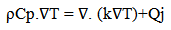 | (2) |
Where, ρ is the electrical resistivity of heater material, Cp is the heat capacity at constant pressure of heater material, k is the thermal conductivity of the heater material and ∇V is the temperature difference across the heater material. The temperature distribution in the pore micro-hotplate is depicted in Figure. 2. 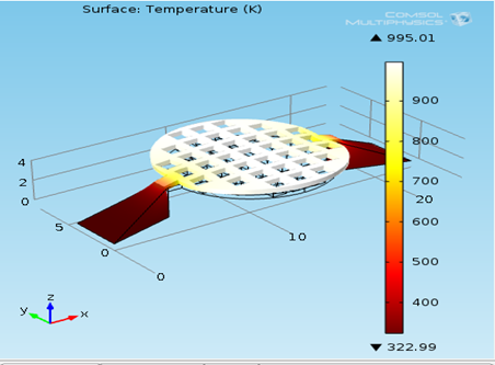 | Figure 2. Temperature distribution in pore micro hotplate |
3.2. Gas Capture
The laminar flow condition is assumed for the flow on this device and therefore Navier-Stokes equation is used to model the laminar flow inside the micro-fluidic channel.  | (3) |
 | (4) |
Where, p is the pressure at the inlet, ρ is the density of the air; µ is the dynamic viscosity of the air. Laminar flow boundary conditions are as follows: At the opening of the chamber i.e., u = 2x10⁻⁵ m/s at the rear end of the chamber, p=1 atm and at the walls, u = 0 m/s.The mass transport of the analyte through the sensing micro-disc is modeled by the following mass transport equations.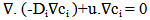 | (5) |
 | (6) |
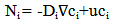
Where, Di is the diffusion coefficient of analyte in air, ci is the analyte concentration, u is the velocity field and Ni is the total flux of analyte transport. The metal oxide- micro-disc reacts with the analyte.The concentration at the outlet, | (7) |
The following condition is applied for the coating.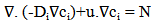 | (8) |
Where, N is the reaction rate in mol/m3/s. The ‘no flux’ condition is applied to the walls, i.e. | (9) |
The mathematical model was implemented in COMSOL Multiphysics. The governing equations and the boundary conditions are provided in the model. Size-adaptive tetrahedral meshing is used to solve the equations.
3.3. Optimized Solution
The PDEs 1, 3, 4 and 9 were optimized to maximize the capture of analyte in the sensing micro-disc. At 50°C, the capturing of NO2 and H2 in air of concentrations 100 ppm and 2000 ppm respectively is maximum at the air flow velocity of 20 μm/s, as shown in Figure 3. The number of micro-discs required to detect the concentration of NO2 and H2 in air is 4.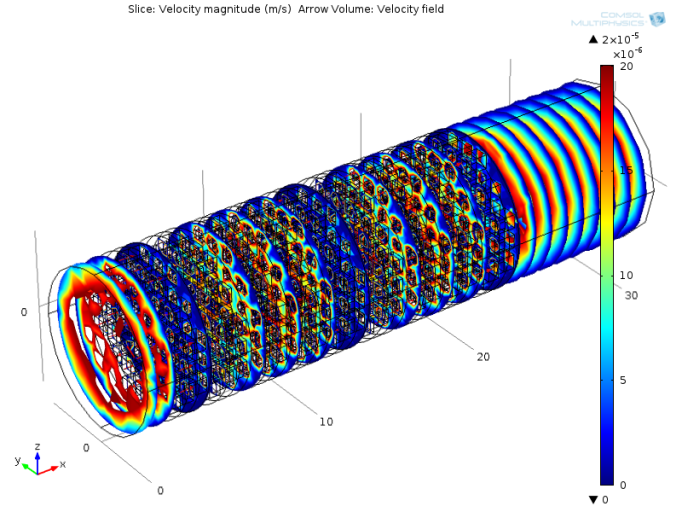 | Figure 3. Velocity profile of the air flow in the chamber |
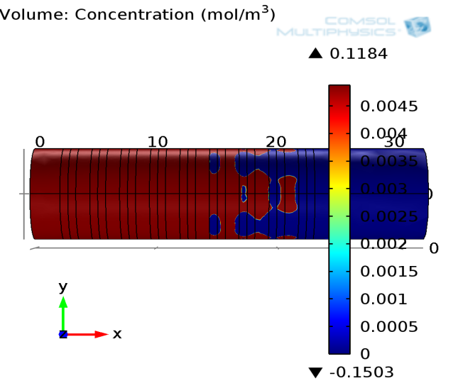
The concentration profile of NO2 and H2 gases are shown in Figure 4 and 5. The 100 ppm of NO2 gas suspended in air is sent in at the inlet. As shown in the Figure 5, the concentration of gas gradually decreases as it goes through the chamber. This is due to its capture in the conductive Silicon micro-discs. After getting diffused through 4 micro-discs, the NO2 concentrations dip to almost 0.  | Figure 4. Concentration profile of NO2 gas in the Chamber |
 | Figure 5. Concentration profile of H2 gas in the Chamber |
Similar mechanism takes place in the case of H2 gas. In this case, H2 gas of 2000 ppm concentration is captured by Pd micro-disc. The relative change in the resitance of the micro-discs is directly relative to the concentration of analyte captured. The ‘m’ and ‘n’ sensing micro-discs are connected in series respectively. This way, the measurement of the overall relative change in the resistance will help us in finding out the concentration of different analytes suspended in the air flowing through the chamber. The relative change in resistance has been plotted as shown in Figure 6 and 7. 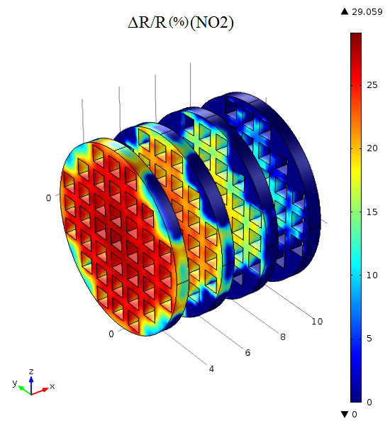 | Figure 6. Relative change in resitance of Si micro-disc |
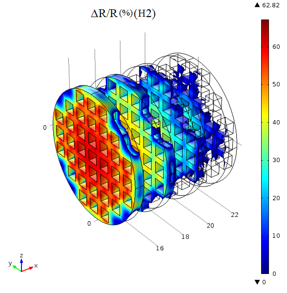 | Figure 7. Relative change in resitance of Pd micro-disc |
In the Figures 6 and 7, the bluish blocks represent the hollow region and the reddish blocks represent the micro hotplate. The relative change in the resistance of the Si and Pd micro-disc has been plotted in the figures 6 and 7 respectively. These micro-discs should be electrically connected in series separately to get the overall system response for each analyte.
4. Conclusions
A tube shaped micro gas sensor system has been designed for the selective capture of NO2 and H2 gases from the air. The results show that the optimal velocity of the air flow in the chamber is 20 μm/s. Further, a micro hotplate has been design to heat the micro-discs to 50°C. The resistance change due to chemical absorption of the gases can be quantified using signal processing circuits, thereby paving way for the detection of gas analytes.
ACKNOWLEDGEMENTS
Authors are highly thankful to MEMS and Nanotechnology Center at Birla Institute of Technology and Science, Dubai Campus, Dubai, UAE.
References
| [1] | Monika and Arti Arora, ‘Design and Simulation of MEMS based Microhotplate as Gas Sensor’ International Journal of Advanced Research in Computer Engg. & Technology, Volume 2, Issue 8, August 2013, pp. 2487-2492. |
| [2] | Velmathi. G, Ramshanker. N and Mohan. S, ‘2D Simulations and Electro-Thermal Analysis of Micro-Heater Designs Using COMSOLTM for Gas Sensor Applications’, COMSOL 2010, Bangalore, India. |
| [3] | Susmita Sinha, Sunipa Roy and C. K. Sarkar, ‘Design & Electro-Thermal Analysis of Microheater for Low Temperature MEMS based Gas Sensor’ International Symposium on Devices MEMS, Intelligent Systems & Communication (ISDMISC) 2011, Majhitar, Sikkim, India. |
| [4] | Jungkyu Kim and Bruce K. Gale, ‘Geometric Optimization of a thin film ITO Heater to generate a uniform temperature distribution’ COMSOL 2010, Bangalore, India. |
| [5] | G. Sureshkannan and G. Mohan Kumar, ‘Experimental Investigation and 2-D Thermal Analysis of High Temperature Microtubular Heater’ European Journal of Scientific Research, Vol.74 No.3 (2012), pp. 403-411. |
| [6] | Xian Yi, Jianjun Lai, Huafeng Liang and Xiaofeng Zhai, ‘Fabrication of a MEMS micro-hotplate’, Journal of Physics: Conference Series, 276, 2011. |
| [7] | Nicolas Dufour, Corinne Wartelle and Philippe Menini, ‘3D Stationary and Temporal Electro-Thermal Simulations of Metal Oxide Gas Sensor Based on a High Temperature and Low Power Consumption Micro-Heater Structure Using COMSOL 2011, Bangalore, India. |
| [8] | F. Udera and J.W. Gardener, ‘Design and Simulations of SOI CMOS Microhot plate gas sensor’, Sensor and Actuators, 2001, Vo1.1, 180-190. |
| [9] | A. Wisitsoraat, A. Tuantranont, and T. Lomas, ‘Design and Simulation of Electro-fabricated MEMS Microhotplate for Gas Sensor Applications’, Journal of Physics: Conference Series, 34 (2006) 643–649. |
| [10] | Woo-Jin Hwang, Kyu-Sik Shin, Ji-Hyoung Roh, Dae-Sung Lee and Sung-Hoon Choa, ‘Development of Micro-Heaters with Optimized Temperature Compensation Design for Gas Sensors’ Sensors2011, 11. |
| [11] | P. Furjes, P. Csikvari, I. Barsony and Cs. Ducso. ‘Hot plates for thermal characterization of structural materials of MEMS’ Budapest Hungary, Sep.2007. |
| [12] | A.A. Ayon, K. Ishihara, R. A. Braff, H. H. Sawin, and M. A. Schmidt, ‘Microfabrication and testing of suspended structures compatible with silicon-on-insulator technology’, Microsystems Technology Laboratories, Massachusetts Institute of Technology, Cambridge, Massachusetts 02139, Received 16 February 1999; accepted 21 May 1999. |
| [13] | Gaoshan Jing, Amy Polaczyk, Daniel B. Oerther, Ian Papautsky, ‘Development of a microfluidic biosensor for detection of environmental mycobacteria’ Sensors and Actuators, 123, (2007) 614–621. |
| [14] | J. Suehiro, N. Ikeda, A. Ohtsubo and K. Imasaka, ‘Bacterial detection using a carbon nanotube gas sensor coupled with a microheater for ammonia synthesis by aerobic oxidization of organic components’, IET Nanobiotechnol., 2009, Vol. 3, Iss. 2, pp. 15–22. |
| [15] | Adarsh Venkataraman Ganesan, Hardeep Kumar, Sundaram Swaminathan and K.K. Singh, ‘Design of MEMS based Micro-Hot Plate for integrated poisonous gas sensing system’, International Conference on Computational Modeling, Simulation and Analysis, Jan. 2013, Dubai, UAE. |
| [16] | Hardeep Kumar, Anuj Kumar, K.K. Singh, Neeru Sood, R.K. Mittal, “Design and Simulation of a Micro Hotplate for MEMS based Integrated Gas Sensing System,” 2014 IEEE Sensors Applications Symposium, Queenstown, New Zealand, Feb. 2014. |
 Abstract
 Reference
 Full-Text PDF
 Full-text HTML