Microelectronics and Solid State Electronics

p-ISSN: 2324-643X    e-ISSN: 2324-6456

2014;  3(1): 1-10

doi:10.5923/j.msse.20140301.01

Modeling of PHEMTs for Superior Switch Transconductance Profile

Christopher Liessner, Samson Mil’shtein

Electrical and Computing Engineering, University of Massachusetts, Lowell, USA

Correspondence to: Christopher Liessner, Electrical and Computing Engineering, University of Massachusetts, Lowell, USA.

Email:

Copyright © 2014 Scientific & Academic Publishing. All Rights Reserved.

Abstract

A high, flat transconductance profile for RF FET switches has been typically considered best for good switch performance. However, analysis shows that a sharp, peaked profile would serve better for switches while a flat profile is optimal for amplifiers. Using Silvaco Atlas, suggested minor variations to a typical pHEMT structure can result in a transconductance profile more conducive to superior switch performance are presented.

Keywords: FET switch, PHEMT switch, RF switch, Transconductance profile

Cite this paper: Christopher Liessner, Samson Mil’shtein, Modeling of PHEMTs for Superior Switch Transconductance Profile, Microelectronics and Solid State Electronics , Vol. 3 No. 1, 2014, pp. 1-10. doi: 10.5923/j.msse.20140301.01.

1. Introduction

Pseudomorphic High Electron Mobility Transistors (pHEMTs) are commonly utilized as microwave switches for many growing transmit / receive (t/r) applications, such as hand-held wireless communication devices, including cell phones, tablets, and GPS systems [1-9]. As the communication architectures evolve, so do the requirements of the components that make up those systems, requiring higher frequencies and corresponding bandwidths while simultaneously delivering greater linearity [1, 5, 7-9]. Much effort over the past several years to improve switch linearity have focused on pHEMTs in particular. This is due to their inherently lower noise and higher linearity characteristics than a standard MESFET [1, 10, 35, 36] as well as better integration than diodes [10, 11, 37]. To date, all modeling of pHEMTs has been done viewing the transistor as simply a microwave device or as an amplifier [12-34]. This paper will introduce a new way of viewing the parameters of a FET switch, specifically a pHEMT, and suggest specific modifications that, along with state-of-the-art switch design methods, will provide additional improvement to linearity.

2. Background

Researchers have been working steadily to improve pHEMT linearity, and several approaches have been successful. In 2005, Yueh-Chin Lin et.al. found that the IP3/PDC ratio can be improved by doping in channel or the Schottky layer of an InGaP/InGaAs pHEMT [38]. These doping changes yield to a broader transconductance curve in both cases, but channel doping resulted in higher gm while the Schottky layer doping resulted in a flatter curve. Interestingly, the original δ-doping profile, used for comparison, resulted in the highest, sharpest gm shape. Thus their approach to linearity, while good for amplifiers, was a step backward for switches. Mil’shtein and Liessner, et. al., proposed both shifted gate and field plate solutions [39–41] in 2006. H. C. Chiu, et.al adjusted the doping ratios of a double heterojunction pHEMT to improve linearity and current density in 2007 [42]. While this increased the gm, it did not provide an ideal switch profile. Y.S. Lin, et.al. demonstrated in 2011 that by passivating the surface of the AlGaAs barrier with ammonium polysulfide, they improved the gm by over 16%, and also achieved a slightly sharper transconductance profile [43]. The effects of passivating the surface has improved switching-speed performance in earlier studies as well [44]. The theory behind the passivation is that it ideally removes the dangling surface state potentials. The author notes here that for a switch where Coff is critical, care must be made in choosing a passivation with the lowest dielectric constant.
Despite the linearity improvements made on pHEMTs in general, a major source of non-linearity in switch applications is the modulation of the gate voltage – in both states. This occurs due the coupling of the RF signal from the source and drain onto the gate. Caverly originally noted the distortion happening during the ON state of a MESFET [45]. This source of nonlinearity in switches is due to the variation of the ON state resistance (Ron). In practice, the control signal that determines the state of the switch often has ripple, noise, and/or unintended modulation on it. While this is well understood in the industry, and there has been some work to minimize this effect [45-47], these authors have found no previous effort to create a FET switch with a transconductance profile that differs from a good amplifier. Many models used for FET switches are often the same as used for amplifiers; the basic FET structure is the same [19-34]. The only difference is that a switch wants to operate exclusively in the saturated region and most amplifier applications prefer the linear region. Nonetheless, good amplifier characteristics are perceived as being good for switches as well, particularly high operating current and high, flat transconductance (gm) [1, 48-51].

3. Theory

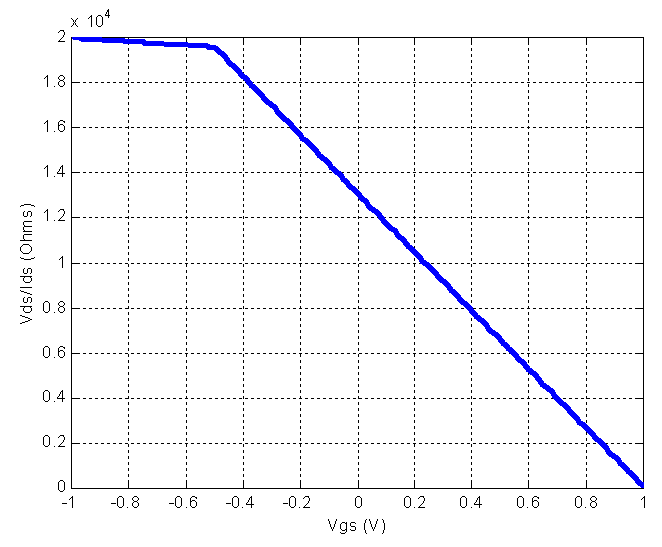
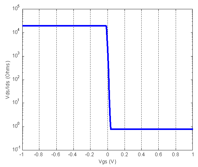
It is proposed that the basic I-V characteristics and the transconductance for a switch should be different from an amplifier for maximized switch performance. In an ideal amplifier, the device should be linear – that is the drain current should change linearly with the gate voltage in the active region. For an ideal switch, the device should be highly non-linear; either it is in the ON state or the OFF state with minimal transition of the gate voltage. Both applications want to maximize the operating current (Ids). For amplifiers it is for higher power, and for switches it is for lower Ron; the difference is in how the device achieves its Ids. This is exactly what the transconductance profile describes. As mentioned earlier, previous researchers have chosen the same optimal profile for amplifiers and switches – that is a high, flat transconductance. What is proposed is that an impulse-shaped transconductance is ideal for improving switch linearity. The following six figures have been derived by the authors using MATLAB. These have been based upon typical pHEMT devices with 0.5μm gate, 1mm periphery, approximately 1.3Ω Ron at Vgs = 0V. Transconductance was calculated at Vds = 3V. Figure 1 shows an example of the Ron characteristic for a typical pHEMT used as an amplifier. These authors have found no literature that separates good pHEMT amplifier performance from good switch performance – in fact a good pHEMT design is considered to be good for all applications. This is not true if an excellent switch design is truly required of pHEMTs (or any FET device). Refer to Figure 2 as an example of a near ideal FET switch Ron characteristic.
Figure 1. Example Ron characteristic for a linear amplifier
Figure 2. Ron characteristic of a near ideal FET switch
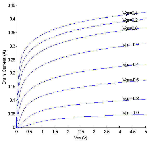
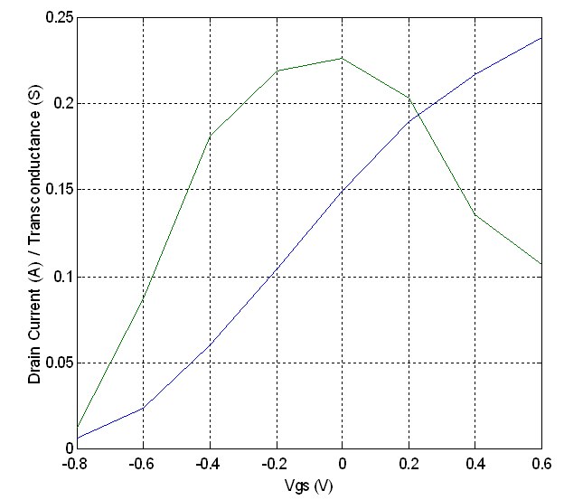
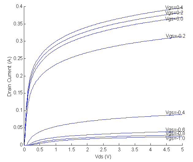
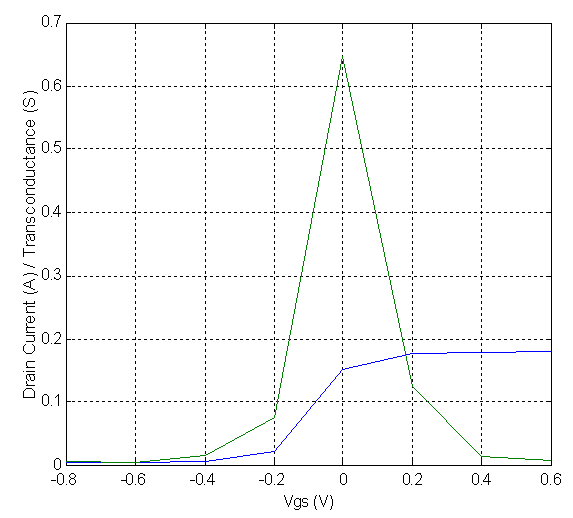
As can be seen, the Ron characteristic in Figure 2 is dramatically different from the one in Figure 1. These characteristics are directly related to the I-V curves of the FETs and their associated transconductance. Typical I-V curves for a depletion-mode FET can be found in Figure 3, with its associated Ids,Vds constant (blue) and gm curves shown in Figure 4. Likewise, the desired I-V curves for a near-ideal depletion-mode FET is displayed in Figure 5, with its associated Ids,Vds constant (blue) and gm curves shown in Figure 6.
Figure 3. Typical FET I-V curves
Figure 4. Typical FET transconductance curve
Figure 5. Near ideal switch FET I-V curves
Figure 6. Near ideal switch FET transconductance curve
As mentioned throughout this paper, transconductance should be flat for an amplifier for ideal linearity; for a switch it should be an impulse. Another way to examine switch performance is to look at the region in the IV curve where the drain current crosses zero. In the “ON” mode of a switch, the source-to-drain voltage should be virtually the same. A Ron of zero – an ideal ON condition – implies that the source-to-drain are actually at equal voltages. Thus it is important to examine the region of Vds near zero. A flat IV line indicates the resistance in the channel is infinite; the inverse of the slope of the IV curve in that region denotes the Ron. The steeper the curve, the lower the ON resistance is. For an ideal switch, for selected values of Vgs, the IV curve should be flat, and then for another adjacent set of gate voltage values, the IV curve should be as steep as possible, with minimal transition of the gate voltage. For example, an idealized pHEMT switch would be in the ON state (i.e., steep IV slope) when the voltage is greater than pinch-off on the gate terminal. Then, as soon as the gate voltage goes below the pinch-off voltage, the switch should be in the OFF state.

4. Simulations

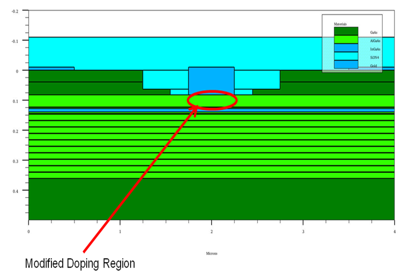
Using electric field tailoring as pioneered by S. Mil’shtein, it is possible to shape the profile of the transconductance [48, 49]. One way to accomplish this is to vary the doping concentrations under in the channel. To create a modified electric field under the gate without changing the effective field elsewhere, and without using multiple gates, it was postulated that varying the concentration of available carriers – immediately under the gate – would work. Silvaco Atlas was used to create and simulate a pHEMT with varied doping under the gate. Figure 7 presents a cross-sectional image of the pHEMT model.
Figure 7. Silvaco Atlas pHEMT model cross-section
Three simulation cases are presented here: 1) a baseline model for comparison, 2) a version with reduced delta doping under the gate, and 3) a version with increased delta doping under the gate. The baseline doping was 8e18 cm-3. The reduced doping case had 4e18 cm-3 under the gate and 8e18 cm-3 elsewhere. The increased doping version has 9e18 cm-3 under the gate and 8e18 cm-3 elsewhere. All three models were created and simulated using Silvaco Atlas. To achieve the modified doping profiles on a real wafer, four process steps would be different, with the last three as extra steps:
1. Dope the entire length at the minimum doping level.
2. Mask the positions with the lesser doping level.
3. Dope unmasked areas to the maximum level.
4. Remove mask.

5. Results

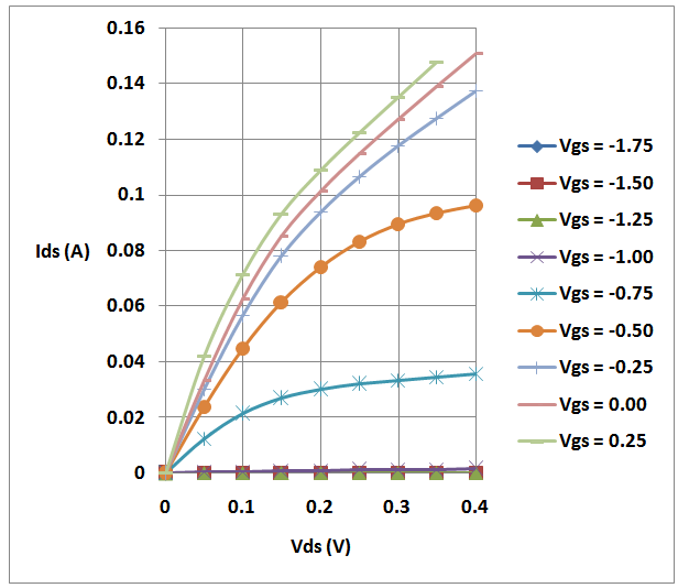
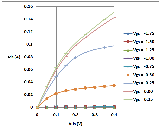
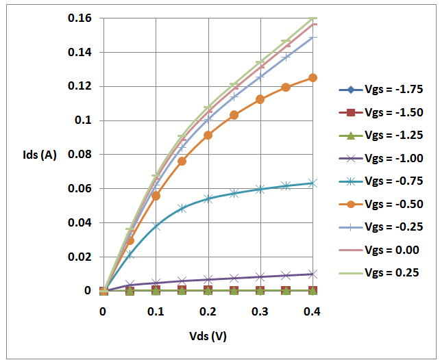
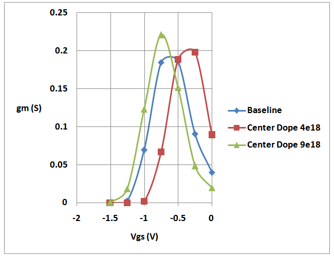
Figures 8, 9, and 10 display the simulated I-V curves generated using Silvaco Atlas for the baseline model, the reduced doping, and the increased doping respectively. Figure 11 shows the transconductance profile for each model.
Figure 8. Baseline pHEMT model simulated IV curves
Figure 9. pHEMT model with reduced doping under gate simulated IV curves
Figure 10. pHEMT model with increased doping under gate simulated IV curves
Figure 11. Tranconductance profiles of three pHEMT models

6. Discussion

Previous work on electric field tailoring has implied that there are several physical adjustments that can be made to the pHEMT structure to make the transconductance profile as sharp as possible. Of the three simulated models presented, the one with increased doping under the gate shows a higher and sharper transconductance profile, and a lower Ron than either the baseline version or the model with reduced doping under the gate. The peak transconductance for the increased doping model measures at 212mS, whereas the model with reduced doping and the baseline are at 201mS and 190ms respectively. Ron for the increased doping model is calculated to be 1.54 ohms, whereas the baseline model and reduced doping model report 1.67 ohms and 1.7 ohms respectively. The profile is also shifted somewhat toward a more negative Vgs, better centering of the peak transconductance between ON and OFF control voltages (typically 0V and -3V respectively). This, as shown through calculations is closer to the ideal profile for a switch. The one drawback to this superior pHEMT is that three extra process steps may be required to realize it physically. It is reasoned that the extra charge provided by the carriers under the gate provide the sharper response that is seen by the model with increased doping, and the narrowness of the response is due to the limited region in which the extra charges are available.

7. Conclusions

With this method, a variation in pHEMT doping is shown through simulation as providing a superior switch transconductance profile, specifically a slight increase in doping under the gate. This, however, comes at the price of additional process steps. Nonetheless, these new tools provide future pHEMT switch designers another path to improved linearity.

ACKNOWLEDGEMENTS

The authors wish to acknowledge the support of the AETC lab of the University of Massachusetts, Lowell ECE department for carrying out the simulations.

References

[1]  Samson Mil’shtein, P. Ersland, “Progress of quantum electronics and the future of wireless technologies,” Microelectronics Journal, vol. 39, issues 3-4, March–April 2008, pp. 669-673.
[2]  S. Mil’shtein, C. Liessner, “High Speed switch using pairs of pHEMTs with shifted gates,” Microelectronics Journal, vol. 36, issues 3-6, March-June 2005, pp. 316-318.
[3]  Christopher W. Liessner. 2005. “A high speed RF switch using shifted-gate pHEMTs,” University of Massachusetts, Lowell.
[4]  Michael Roberts, Lutfi Albasha, Wolfgang Bosch, Damian Gotch, James Mayock, Pallavi Sandhiya, Ian Bisby, “Highly Linear Low Voltage GaAs pHEMT MMIC Switches for Multimode Wireless Handset Applications,” IEEE Radio and Wireless Conference, August 19-22, 2001, pp. 61-64.
[5]  Zeji Gu, Dave Johnson, Steven Belletete, Dave Fryklund, “Low Insertion Loss and High Linearity PHEMT SPDT and SP3T Switch ICs for WLAN 802.11a/b/g Applications,” IEEE Radio Frequency Integrated Circuits (RFIC) Symposium, Digest of Paper, June 6-8, 2004, pp. 505-508.
[6]  J. A. del Alamo, “The High Electron Mobility Transistor at 30: Impressive Accomplishments and Exciting Prospects,” International Conference on Compound Semiconductor Manufacturing Technology, May 16-19, 2011, pp. 17-22.
[7]  Jay Yang, Rick Cory, “Ultra-Miniature High Linearity SPDT Switch for WLAN Applications,” Microwave Product Digest, February 2010.
[8]  Kevin Walsh, “RF Switches Guide Signals in Smart Phones,” Microwaves & RF, September 2010, vol. 49, issue 9, p. 80.
[9]  Chang-Ho Lee, Bhaskar Banerjee, Joy Laskar, “Novel T/R Switch Architectures for MIMO Applications,” IEEE MTT-S International Microwave Symposium Digest, vol. 2, pp. 1137-1140.
[10]  Robert H. Caverly, “Distortion in Broad-Band Gallium Arsenide MESFET Control and Switch Circuits,” IEEE Transactions on Microwave Theory and Techniques, vol. 39, no. 4, pp. 713-717, 1991.
[11]  Kai Chang, Inder Bahl, Vishay Nair. 2002. “RF and Microwave Circuit and Component Design for Wireless Systems” Wiley, John & Sons, Incorporated, New York, p. 222.
[12]  C. –J. Wei, A. Klimashov, Y. Zhu, E. Lawrence, G. Tkachenko, “Large-Signal PHEMT Switch Model, Which Accurately Predicts Harmonics and Two-Tone Inter-Modulation Distortion,” IEEE MTT-S International Microwave Symposium Digest, June 12-17,2005.
[13]  Yu Zhu, Cejun Wei, George Nohra, Cindy Zhang, Oleksiv Klimashov, Hong Yin, Dylan Bartle, “Electromagnetic Only HEMT Model for Switch Design,” Asia Pacific Microwave Conference, December 7-10, 2009 , pp. 273-276.
[14]  Dong-Ming Lin, Chien-Chang Huang, Yi-Jen Chan, “A Symmetrical Model for Microwave Power AlGaAs/InGaAs pHEMTs for Switch Circuit Applications,” IEEE Transactions on Electron Devices, vol. 56, no. 11, pp. 2638-2643, 2009.
[15]  Ce-Jun Wei, Yu Zhu, Hong Yin, Olesky Klimashov, Dylan Bartle, “A Comprehensive PHEMT Core Model for Switch Applications,” IEEE MTT-S International Microwave Symposium Digest, June 5-10, 2011, pp. 1-4.
[16]  Ce-Jun Wei, Hong Yin, Olesky Klimashov, Yu Zhu, Dylan Bartle, “Multi-gate pHEMT Modeling for Switch Applications,” IEEE Compound Semiconductor Integrated Circuit Symposium, October 14-17, 2012, pp. 1-4.
[17]  Faramarz Kharabi, “Modeling of FET Switches,” IEEE Compound Semiconductor Integrated Circuit Symposium, October 14-17, 2012, pp. 1-4.
[18]  Ce-Jun Wei, Yu Zhu, Alex Klimashov, Hong Yin, Cindy Zhang, Dylan Bartle, “Distributed Switch FET Model that Predicts Better Insertion Loss and Harmonics,” European Microwave Integrated Circuits Conference, pp.238-241.
[19]  P. J. Rudge, R. E. Miles, M. B. Steer, and C. M. Snowden, “Investigation into Intermodulation Distortion in HEMTs Using a Quasi-2-D Physical Model,” IEEE Transactions on Microwave Theory and Techniques, vol. 49, no. 12, pp. 2315-2321, 2001.
[20]  P. R. Pantoja, M. J. Howes, J. R. Richardson, and C. M. Snowden, “A Large-Signal Physical MESFET Model for Computer-Aided Design and Its Applications,” IEEE Transactions on Microwave Theory and Techniques, vol. 37, no. 12, pp. 2039-2045, 1989.
[21]  R. J. Trew, “MESFET Models for Microwave Computer-Aided Design,” Microwave Journal, vol. 33, pp 115-130, May 1990.
[22]  R.B. Hallgren and P. H. Litzenberg, “TOM3 Capacitance Model: Linking Large- and Small-Signal MESFET Models in SPICE,” IEEE Transactions on Microwave Theory and Techniques, vol. 47, no. 5, pp. 556-561, 1999.
[23]  W. R. Curtice, “A MESFET Model for Use in the Design of GaAs Integrated Circuits,” IEEE Transactions on Microwave Theory and Techniques, vol. 28, no 5, pp. 448-456, 1980.
[24]  L. Angelov, N. Roreman, J. Stenarson, M. Garcia, and H. Zirath, “An Empirical Table-Based FET Model,” IEEE Transactions on Microwave Theory and Techniques, vol. 47, no. 12, pp. 2350-2357, 1999.
[25]  J. Gao, X. Li, H. Wang, and G. Boeck, “Empirical All region Current Based PHEMT DC Model,” SBMO/IEEE MTT-S International Microwave and Optoelectronics Conference, 2003. Proceedings of the 2003, vol. 1, no. 9, pp. 99-101.
[26]  G. Qu, A. E. Parker, “Modeling HEMT intermodulation distortion characteristics,” Microelectronics Journal, vol. 31, issue 7, July 2000, pp. 493-496.
[27]  Ristesh Gupta, Sandeep Kumar Aggarwal, Mridula Gupta, R. S. Gupta, “Analytical non-linear charge control model for InAlAs/InGaAs/InAlAs double heterostructure high electron mobility transistor (DH-HEMT),” Solid-State Electronics, vol. 49, issue 2, February 2005, pp. 167-174.
[28]  Michael Wren, Thomas J. Brazil, “Enhanced Prediction of pHEMT Nonlinear Distortion Using a Novel Charge Conservative Model,” IEEE MTT-S International Microwave Symposium Digest, vol. 1, pp. 31-34, June 6-11, 2004.
[29]  Paul M. White, Wolfram C. Stiebler, Philip C. Balas, “Improved Modified Materka Model for Simulation of Pinch-Off Variation in PHEMT Devices,” European Microwave Integrated Circuits Conference, pp. 414-416, September 10-13, 2006.
[30]  Ritesh Gupta, Sandeep k. Aggarwhal, Mridula Gupta, R. S. Gupta, “An analytical model for discretized doped InAlAs/InGaAs heterojunction HEMT for higher cut-off frequency and reliability,” Microelectronics Journal, vol. 37, issue 9, September 2006, pp. 919-929.
[31]  B. Luo, Y. X. Guo, S. Y. Wong, L. C. Ong, “Modeling of 0.15μm InGaAs pHEMT up to 60 GHz,” IEEE International Workshop on Radio-Frequency Integration Technology, 2007, December 9-11, 2007, pp. 286-289.
[32]  Ce-Jun Wei, Yu Zhu, Hong Yin, Oleksiy Klimashov, Cindy Zhang, Tzung-Yin Lee, “Capacitance and RF-Conductance/ Transconductance Look-up Table Based pHEMT Model,” Asia-Pacific Microwave Conference Proceedings, December 5-8, 2011, pp. 1246-1249.
[33]  A. Raffo, A Santtarelli, P.A. Traverso, M. Pagani, F. Palomba, F. Scappaviva, G. Vannini, F. Filicori, “Improvement of PHEMT Intermodulation Prediction Through the Accurate Modelling of Low-Frequency Dispersion Effects,” IEEE MTT-S International Microwave Symposium Digest, June 12-17, 2005.
[34]  Masaya Iwamoto, Jianjun Xu, Jason Horn, David E. Root, “III-V FET High Frequency Model with Drift and Depletion Charges,” IEEE MTT-S International Microwave Symposium Digest, June 5-10, 2011, pp. 1-4.
[35]  Zeji Gu, Shuyun Zhang, David Johnson, Steve Belletete, Mark Ayvazian, Dave Fryklund, “A High-Performance GaAs SP3T Switch for Digital Cellular Systems,” IEEE MTT-S International Microwave Symposium Digest, May 20-24, 2001, vo. 1, pp. 241-244.
[36]  Yen-Wei Chen, Wei-Chou Hsu, Rong-Tay Hsu, Yue-Huei Wu, Yeong-Jia Chen, “Characteristics of In0.52Al0.48As/ InxGa1-xAs HEMT’s with various InxGa1-xAs channels,” Solid-State Electronics, vol. 48, issue 1, January 2004, pp. 119-124.
[37]  A. M. Street, “RF Switch Design,” How to Design RF Circuits (Ref. No. 2000/027), IEEE Training Course, 2000, pp. 4/1-4/7.
[38]  Yueh-Chin Lin, J. W. Chang, Edward Yi Chang, X. Y. Chang, “On the Doping Effects for Linearity Improvement of InGaP/InGaAs PHEMT,” Asia-Pacific Microwave Conference Proceedings, vol. 2, December 4-7, 2005.
[39]  S. Mil’shtein and C. Liessner “Field Effect Transistor with Shifted Gate” Patent# 11,407,381 (2006)
[40]  S. Mil’shtein, J.Palma, and C. Liessner “Field Effect Transistor with Independently Biased Gates” Patent # 11,406,838 (2006)
[41]  C. Liessner, J. Barrett, J. Palma, D. Gleason, and S. Mil’shtein, “Improving FET Switch Linearity”, Electron Devices, Vol. 54, Number 3, March 2007, pp. 391-397.
[42]  H. C. Chiu, C. W. Chen, Y. C. Huang, R. J. Yang, “RF Performance of Double Heterojunction High Mobility Transistor with Various Lower/Upper Plana Doping Ratio Designs on SPST Switchs Application,” Asia-Pacific Microwave Conference, December 11-14, 2007, pp. 1-4.
[43]  Y. S. Lin, S. K. Liang, “Improved AlGaAs/InGaAs High-Electron Mobility Transistor,” IEEE Transactions on Microwave Theory and Techniques, vol. 41, issue 5, pp. 752-759, 1993.
[44]  Andrew Freeston, Costas Varmazis, Timothy Boles, “Nanosecond pHEMT Switches,” European Microwave Integrated Circuits Conference, September 28-29, 2009, pp. 13-16.
[45]  Robert H. Caverly, “Distortion in Off-State Arsenide MESFET Switches,” IEEE Transactions on Microwave Theory and Techniques, vol. 41, no. 8, pp. 1323-1328, 1993.
[46]  Andrew Dearn, Liam Devlin, Wing Yau, Owen Yu, “Design Trade-offs for High Linearity pHEMT Switches,” 53rd IEEE International Midwest Symposium on Circuits and Systems, August 1-4, 2010, pp. 942-945.
[47]  Shigeki Koya, Takashi Ogawa, Hiroyuki Takazawa, Akishige Nakajima, Shinya Osakabe, Yasushi Shigeno, Shinichiro Takatani, “Intergate-Channel-Connected Multi-Gate PHEMT Devices for Antenna Switch Applications,” IEEE MTT-S International Microwave Symposium Digest, June 15-20, 2008, pp. 1287-1290.
[48]  S. Mil’shtein, P. Ersland, S. Somisetty, C. Gil, “p-HEMT with tailored field,” Microelectronics Journal, vol. 34, no.5, May 2003, pp. 359-361.
[49]  S. Mil’Shtein, “Shaping electrical field in heterostructure transistors,” Microelectronics Journal, vol. 36, issues 3-6, March-June 2005, pp. 319-322.
[50]  Walter A. Wohlmuth, Wolfgang Liebl, Varun Juneja, Robert Hallgren, Wayne Struble, Domingo Faria, Paul Litzenberg, Otto Berger, “E-/D-pHEMT Technology for Wireless Components,” IEEE CSIC Symposium, 2004, pp. 115-118.
[51]  Sobhana V. Gudimetta. 2003. “Control of HEMT performance by changing the quantization conditions for electrons,” University of Massachusetts, Lowell.