-
Paper Information
- Next Paper
- Paper Submission
-
Journal Information
- About This Journal
- Editorial Board
- Current Issue
- Archive
- Author Guidelines
- Contact Us
Microelectronics and Solid State Electronics
p-ISSN: 2324-643X e-ISSN: 2324-6456
2013; 2(3): 39-44
doi:10.5923/j.msse.20130203.01
Design and Analysis of Microgripper for Various Piezoelectric Materials
 Abstract
 Reference
 Full-Text PDF
 Full-text HTML
Simmerdeep Kaur, Balwinder Singh
Centre for Development of Advanced Computing, Mohali, 160062, India
Correspondence to: Simmerdeep Kaur, Centre for Development of Advanced Computing, Mohali, 160062, India.
| Email: |  |
Copyright © 2012 Scientific & Academic Publishing. All Rights Reserved.
Micro Electro Mechanical System (MEMS) is a highly miniaturized device or an array of devices combining electrical and mechanical components. The microgripper uses a piezoelectric stack actuator for the parallel movement of gripping arms. Microgripper is a device used to grip and handle various micro or nano objects. In this paper the mathematical model of the micro gripper is proposed and its effects on the displacement are analyzed in MATLAB. The microgripper is designed in COMSOL for different piezoelectric materials such as lead zicronate titanate, Bismuth germinate and barium titanate and obtained results are compared with theoretical results.
Keywords: Microgripper, Actuator, Piezoelectric Materials
Cite this paper: Simmerdeep Kaur, Balwinder Singh, Design and Analysis of Microgripper for Various Piezoelectric Materials, Microelectronics and Solid State Electronics , Vol. 2 No. 3, 2013, pp. 39-44. doi: 10.5923/j.msse.20130203.01.
Article Outline
1. Introduction
- Micro Electric Mechanical System or Microsystems is an emerging technology, it has a big potential to reshape life patterns for future microelectronics technology. This technology is used in many application areas, including automotive, biomedical, telecommunication, consumer electronics and also in defense application. It is expected that the MEMS technology will make the potential use of nano technology through it, performance and application area of MEMS product will enhance. During recent years, with the increasing effort to minimize the system and products in industries, the need for micro and nanotechnology has become important issues. The problem of handling the micro optical and micro electrical elements in nano or micrometer range can be solved by using special micro gripper. In the gripping process, the reaction forces operate between the object to be gripped and the microgripper arms. The reaction forces act perpendicular in case of micro objects with curved or circular surfaces. This can be explained on the basis of Newton’s third law. During gripping action the normal reaction of the object to be gripped acts on the microgripper jaws and a component of this force acts downwards. Because of this F’COSѲ component, the gripped object will have a tendency to move downwards and this tendency keeps on increasing with the increase in applied force and finally the object would slide from micro gripper arms as shown in figure 1. Therefore it is hard for the gripper to grip the objects efficiently and certainly the issue sets a limit on the force, which can be applied by the gripping jaws, on the object to be gripped. This performance bottleneck can be avoided if the gripping process can be obtained without any rotational like movement of the jaws as shown in Figure 2. This can be realized by using a mechanism with parallel movement of the gripping arms while they grasp or release micro objects as shown in Figure (2). Ѳ is 90 degree which Results in (FcosѲ) to be zero .Hence the probability of the object to slide from gripping arms is reduced.
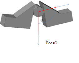 | Figure 1. Non parallel arm movement |
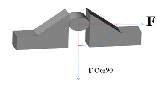 | Figure 2. Parallel Arm movement |
2. Related Work
- Various researches have been carried out in microgripper. H.Noori[1] deals with the study of effect of frequency on a microgripper which uses piezoelectric actuator. In this different control approaches that are used in piezoelectric microgripper are investigated and compared. In this paper a novel concept is defined to study about deviation of microgripper displacement. Jose A. Martiez[2] Experimental results are presented for both the actuation techniques along with failure analysis.[3] Pradhan, R this paper study with the parallel microgripper was micro fabricated and tested successfully. Xiangjin Zing[4] deals with the improved the efficiency of microgripper. Achkar, H[5] this paper presents a stimulation of mems based three electrode device using comsol multiphysics. The impedance data obtained from comsol simulation was fitted by using the equivalent circuits of PSB. Syaifudin[5] Electromagnetic field analysis of interdigital sensor has been carried out, it was observed simulation results using comsol multiphysics, the novel interdigital sensor with configuration sensor one had better sensitivity measurement compared to other novel interdigital sensor.
3. Structural Analysis
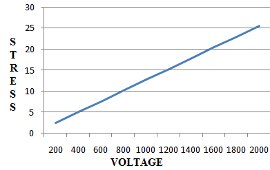
- The different material used for microgripper designs, In structural analysis we investigate the effects on stress by applying the potential voltage(a) In first case the actuator is made lead zicronate titanate of piezoelectric material and the gripper consist of polysilicon. Again both the material is presented in the COMSOL libraries and is arranged by rotating coordinate system. The reading has been observed from COMSOL. However by applying the potential voltage it can effect on the stress (µPa). In which we are observe the different values of stress on different voltage (µV).(b) In second case the actuator is made bismuth germanate of piezoelectric material and the gripper consist of polysilicon. Again both the material is presented in the COMSOL libraries and is arranged by rotating coordinate system. The reading has been observed from COMSOL. However by applying the potential voltage it can effect on stress. In which we are observe the different stress on different voltage.
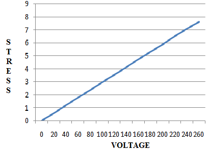 | Figure 3. stress (µPa) v/s voltage (µV) for lead zicronate titanate |
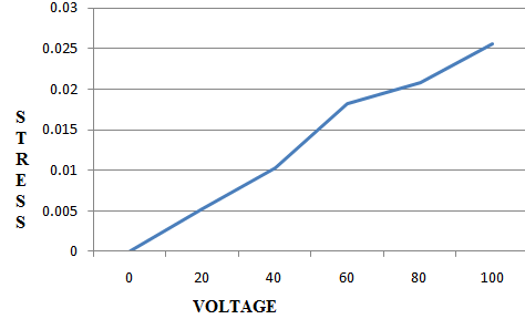 | Figure 4. stress (µPa) v/s voltage (µV) for Bismuth germanates |
 | Figure 5. stress (µPa) v/s voltage (µV) for Barium Titanate |
4. Mathematical Model of Piezoelectric Microgripper[1]
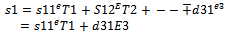
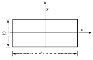
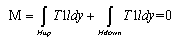
- Piezoelectric microgripper uses the curved type piezoelectric bimorph cantilever as finger, two fingers with symmetrical. In the figure of 3 we ignore the thickness of the middle layer. As the beam length is greater than of its width and the second stress of cantilever is t1=t2=t3=t4=t5=t6=0, strain s1, s2, s3, s4, s5, s6≠0 so according to the first piezoelectric equation, we obtain the strain of piezoelectric layer .
 | (1) |
 .Where E= Coefficient in the electric field.D31= Piezoelectric strain coefficient.E3 = Electric field, T1=stress tensor.
 | (2) |
 | Figure 6. |
 | (3) |
 | (4) |
 | (5) |
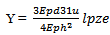 Lpze= length of piezoelectric actuator.
5. Design and Comparison
5.1. Design Detail of Microgripper
- In the microgripper actuator is made up of piezoelectric material. The microgripper contains a piezoelectric actuator that operates in the longitudinal mode. Simultaneously contraction in the transversal direction closes the gripper and allows it to move objects. The actuator is made of different materials, and the gripper itself consists of polycrystalline silicon (poly-Si). Both materials are available in COMSOL Multiphysics material libraries.
 | Figure 7. Flow diagram for designing the microgripper |
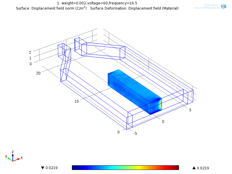 | Figure 8. Microgripper Design In COMSOL[7] |
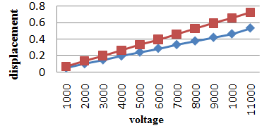
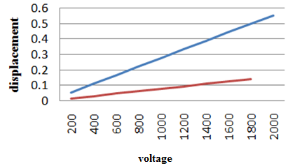
5.2. Study of Voltage/Displacement Relationship for Various Materials
- (a) Lead Zicronate TitanateIn first case the actuator which is made of lead zicronate titanate and the gripper consist of polysilicon. Again both the material is presented in the COMSOL libraries and is arranged by rotating coordinate system. The reading has been observed from COMSOL. After that, readings of the MATLAB are compared with the readings of the comsol.
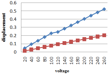 | Figure 9. Displacement v/s voltage for lead zicronate titanate |
 | Figure 10. Displacement v/s voltage for bismuth germinate |
 | Figure 11. Displacement V/S Voltage For Barium Titanate |
|
6. Conclusions
- In this paper several input voltages are applied to the microgripper with different piezoelectric materials such as lead zicronate titanate (PZT-5A), Bismuth germanate and barium titanate. The displacement changes are obtained for different values of applied voltage and are investigated for several closing and openings. The comparisons of the several piezoelectric materials have been done, for example, in first case the actuator is made of lead zicronate titanate (pzt-5a). It required 250 micro volts to grip the object. In second case the actuator is made of bismuth germanate in this 11,000 micro voltage is required to grip the object. In third case actuator is made of barium titanate in which 18,000 micro voltage is required to grip the object and since this much high voltages practically raises the safety concerns. So by comparing these three materials, we preferred the actuator which is made up of lead zicronate because it requires very less voltage as compare to the other two. However strain coefficient of lead zicronate titanate (PZT-5A) is 1.8 *`10-4µm/v.whereas for barium titanate the coefficient of strain is 10-6µm/v becuase lead zicronate titanate has higher value of strain coefficient (almost 200 times more than barium titanate).So that it requires lesser voltage for moving the arms. That’s why lead zicronate titanate (PZT-5A) Material is mostly preferred among these. The simulations of the COMSOL are compared with the readings of MATLAB.