-
Paper Information
- Previous Paper
- Paper Submission
-
Journal Information
- About This Journal
- Editorial Board
- Current Issue
- Archive
- Author Guidelines
- Contact Us
Microelectronics and Solid State Electronics
2012; 1(4): 98-101
doi: 10.5923/j.msse.20120104.05
Programmable Floating Gate Transistor Operating as a Resistor for Analog Applications
 Abstract
 Reference
 Full-Text PDF
 Full-Text HTML
El-Sayed A. M. Hasaneen
Electrical Engineering Department, Faculty of Engineering, El-Minia University El-Minia, 6111, Egypt
Correspondence to: El-Sayed A. M. Hasaneen , Electrical Engineering Department, Faculty of Engineering, El-Minia University El-Minia, 6111, Egypt.
| Email: |  |
Copyright © 2012 Scientific & Academic Publishing. All Rights Reserved.
This paper presents a programmable resistor using two-input floating gate MOS transistor (FGMOST). One of the two-input gates is connected to the drain and the other is connected to a tuned voltage to control the floating gate transistor resistance. A wide range of the programmable resistance is achieved by controlling the tuned voltage. The resistance is changed by 33% by varying the tuned voltage by 0.4 V. Three applications based on FGMOST operated as a resistor are proposed. These are tunable filter, tunable triangular oscillator and tunable amplifier. The cut-off frequency of the low-pass filter is tuned from 21.4 kHz to 32.1 kHz by controlling the tuned voltage by 0.4 V. The oscillation frequency of the triangular oscillator is varied from 336.18 kHz to 540.2 kHz by varying the tuned voltage by 0.4. Also, the gain of the amplifier is changed by 50% by changing the tuned voltage by 0.4 V.
Keywords: Floating Gate Transistor, Programmable Resistor, Low-pass Filter, Triangular Oscillator, Low-voltage Circuits
Cite this paper: El-Sayed A. M. Hasaneen , "Programmable Floating Gate Transistor Operating as a Resistor for Analog Applications", Microelectronics and Solid State Electronics , Vol. 1 No. 4, 2012, pp. 98-101. doi: 10.5923/j.msse.20120104.05.
Article Outline
1. Introduction
- Over the past few years, an increasing demand for designing programmable circuits for many applications is highly demanded. The new advances in the analog circuits made it possible to design tunable devices to achieve programmable, reconfigurable and adaptive circuits. The design of versatile circuits requires tunable devices to achieve programmability. Among the various analog programmable circuits are filters, oscillators, amplifiers, current sources and current mirrors.Multi-input floating-gate MOS transistors (FGMOSTs) have been proven to be promising candidate for low voltage low power applications[1-4]. Also, FGMOSTs have been achieved a tunable functionality[5-11]. FGMOST accepts multiple input signals that control the transistor operation to enhance the transistor functionality. FGMOSTs are used in many applications such as four-quadrant multiplier[7], OTA[6, 11], and audio sensing systems[9].In this paper, two-input FGMOST operates as a programmable resistor has been presented. The resistance of the transistor is varied by tuning one of the gate voltages of the transistor. Three analog circuit applications using the proposed programmable resistor are investigated. These are programmable filters, triangular oscillators and voltage amplifier. A wide-range of the filter cut-off frequency is achieved. Also, the oscillation frequency of the triangular oscillator and the gain of the amplifier are tuned by varying the tuned voltage of the FGMOST.This paper is organized as follows. Section II describes two-input FGMOST. Tunable filter using FGMOST is described in Section III. Tunable triangular oscillator circuit based on programmable resistor of the FGMOST is described in Section IV. Also, tunable voltage gain differential amplifier is presented in Section V. Simulation results are investigated in Section VI. Finally, conclusions are given in Section VII.
2. Two-input Floating Gate Transistor
- Floating gate MOS transistor is similar to a regular enhancement MOS transistor except that it has two gates. Fig. 1 shows two-input floating gate transistor. One gate (bottom gate) is completely surrounded by an insulator called floating gate and the other gate (top gate) is called control gate. The advantage of using two-input is to control the operation of the FGMOST. Fig. 2 shows the equivalent circuit of FGMOST. CFGD, CFGS and CFGB are the capacitances between floating gate and drain, source, and body, respectively. CG1 and CG2 are the capacitances between control gate and floating gate. The floating gate voltage is given by[12]:
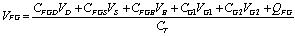 | (1) |
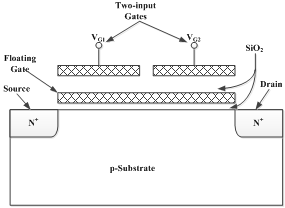 | Figure 1. Structure of two-input floating gate transistor |
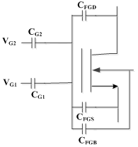 | Figure 2. Equivalent circuit of two-input floating gate transistor |
 | (2) |
 | (3) |
 | (4) |
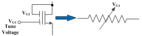 | Figure 3. Two-input floating gate transistor works as resistor |
3. Programmable Low-pass Active filter
- The cut-off frequency of a filter is fixed and dependent on the filter element values. In order to achieve programmable filter, a tunable element should be imposed on the filter circuit. Fig. 4 shows the proposed tunable low-pass active filter. The FGMOST is working as a programmable resistor. The cut-off frequency of the filter is given by:
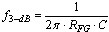 | (5) |
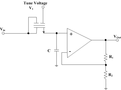 | Figure 4. Tunable low-pass active filter using floating gate transistor |
4. Programmable Triangular Oscillator
- Figure 5 shows the proposed triangular oscillator. Also, the FGMOST is working as a programmable resistor whose resistance value is dependent on the tuned voltage. The oscillation frequency is given by[13]:
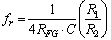 | (6) |
5. Programmable Gain Amplifier
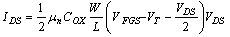
- Tunable gain amplifiers are highly demanded in intelligent circuits. The amplifier voltage gain is fixed after fabrications. Fig. 6 shows the proposed differential amplifier with tunable voltage gain. Two floating gate transistors work as resistors are connected to the both inputs. Both FGMOSTs must be identical and have the same tuned voltage to provide the same resistance. The output voltage of the amplifier is given by:
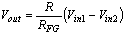 | (7) |
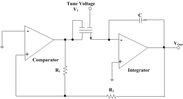 | Figure 5. Tunable triangular oscillator |
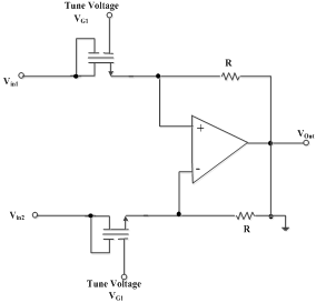 | Figure 6. Tunable voltage gain differential amplifier |
6. Simulation Results
- Fig. 7 shows the resistance of the floating gate transistor operates in the linear region as a function of the tuned voltage. One of the gate terminals is connected to the drain and the other gate is connected to the tuned voltage. A wide range of the resistance is achieved. The resistance is changed from 7.4365 kΩ to 4.96 kΩ a percentage change of 33% by varying the tuned voltage by 0.4 V.Figure 8 shows the variation of the cut-off frequency of active low-pass filter with the tuned voltage. The cut-off frequency is highly dependent on the tuned voltage. It changes from 21.4 kHz to 32.1 kHz by varying the tuned voltage by 0.4 V.Figure 9 illustrates the oscillation frequency of the triangular oscillator with the tuned voltage. The tuned voltage has a large affect on the oscillation frequency. It is changed from 336.18 kHz to 504.2 kHz with a percent change of 50% by varying the tuned voltage by 0.4 V.Figure 10 shows the variation of the differential amplifier voltage gain with the tuned voltage. It illustrates a wide range of the gain variation with the tuned voltage. The voltage gain changes from 107.5776 to 161.3670% by tuning the tuned voltage by 0.4 V
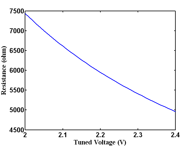 | Figure 7. Variation of the floating gate transistor resistance with tuned voltage |
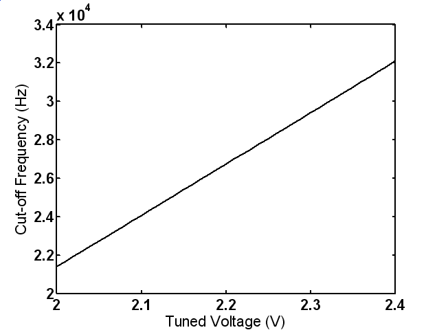 | Figure 8. Variation of the filter cut-off frequency with tuned voltage |
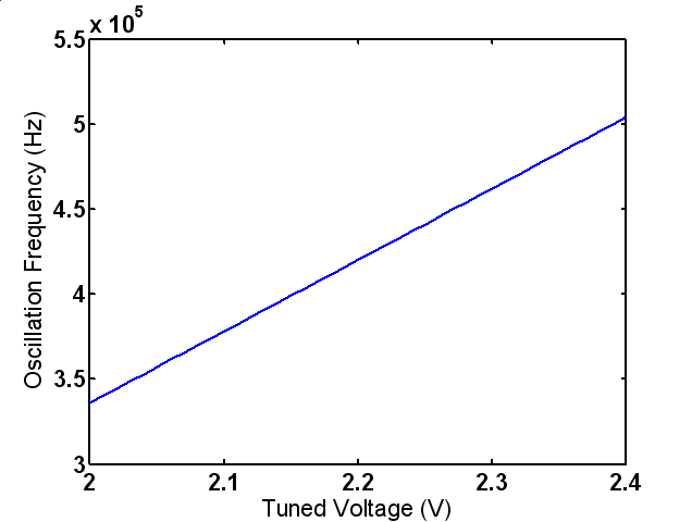 | Figure 9. Variation of the oscillation frequency with tuned voltage |
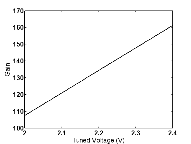 | Figure 10. Variation of the voltage gain with tuned voltage |
7. Conclusions
- Using two-input floating gate transistor as a programmable resistor has been presented. The transistor exhibits excellent control on the resistance by controlling the tuned voltage. The proposed transistor is useful in the designing of the tunable circuits in the state-of-the-art analog circuits. Tunable low-pass filter, triangular oscillator and differential amplifier circuits based on the proposed two-input floating gate transistor are proposed to obtain the tunable functionality. The results show a large range of the tunable functionality achieved by using the floating gate transistor as a programmable resistor.