Ruey Syan Shih1, Wen Kai Weng2, Chung Ren Chou2
1Department of Construction and Spatial Design, Tungnan University, New Taipei City, 22202, Taiwan
2Department of Harbor and River Engineering, National Taiwan Ocean University, Keelung, 20224, Taiwan
Correspondence to: Ruey Syan Shih, Department of Construction and Spatial Design, Tungnan University, New Taipei City, 22202, Taiwan.
| Email: |  |
Copyright © 2012 Scientific & Academic Publishing. All Rights Reserved.
Abstract
This study investigates the variations of spatial velocities and particles trajectories around multiple submerged breakwaters by two-dimensional numerical wave flume established by the boundary element method. The simulations of waves passing over an impermeable submerged dike and a set of double dike are utilized for discussion. The boundaries were discretized by linear elements, and the Lagrangiandescriptions of wave motion are used to describe the variation of flow field around the obstacles cause by wave-obstacle interactions. The trajectories of fluid particles are determined by the instantaneous velocity and the differentiation of time derivatives through forward differencing, and the variations of the trajectories are analyzed and discussed respectively by the path line and velocity field. When the waves propagate over the obstacles, a vortex exists significantly on either side of the upper corner, which rotatescontrarily with the direction of the wave direction. The phenomenon of vortex is more significant when the width and the height of the embankment increased. This was also found in the case of double-column submerged obstacles. Moreover, the existence of vortex was also confirmed in the clip region between the obstacles.
Keywords:
BoundaryElement Method, Spatial Velocity, Particle Trajectory, Submerged Breakwater, Vortex
Cite this paper: Ruey Syan Shih, Wen Kai Weng, Chung Ren Chou, Numerical Modeling of Wave Field around Multiple Submerged Breakwaters, Marine Science, Vol. 3 No. 3, 2013, pp. 65-78. doi: 10.5923/j.ms.20130303.02.
1. Introduction
In recent years, coastal structures, such as breakwaters, artificial reefs and seawalls, have been designed and constructed to produce calmness and ensure urban safety by dissipating the wave energies and forces. With development of technology and society, people gradually attach great importance to the natural ecology of the oceans and the preservation of landscape.Many submerged breakwaters with various forms, are being extensively investigated and discussed as impermeable protecting embankments.Experts and scholars put forward the outstanding results of various types of submerged breakwaters, and hope that the ecological landscape and coastal protection can exist simultaneously. When wave propagates over a submerged breakwater, eddy current exists in the front or rear side of the submerged breakwater,which usually cause damage to the surface of the submerged breakwater or washout to the embankment toe. Submerged dike forced the incident waves to break before or above the obstacles under the impact of wave-obstacle interaction, and cause destruction to the structure of wave. Wave energy is mostly attenuated before reaching theshore, and the wave force is also reduced simultaneously. The movements and trajectories of water particles around the obstacle also affects the activities of drift sand, siltation, coastal washout, and sedimentation, which are the main causes of change-related activities.Therefore, the simulation of waves over a submerged breakwater and the movement of water molecules around the submerged breakwater, including the distributions of the trajectories and velocities of the water molecules are study presently.Ting and Kim (1994)[1] investigated experimentally the flow separation effects induced by time-periodic water waves travelling over a submerged rectangular obstacle, the kinematics and dynamics of eddy motions were studied and compared to the theoretical predictions of a linear inviscid model. Ohyama and Nadaoka (1994)[2] studied numerically the decomposition phenomenon of a nonlinear wave train passing over a submerged shelf, and suggested that when the width of the shelf isnearly one half of the beat length of a higher harmonic amplitude, the magnitude of the corresponding component becomes remarkably large in transmitted waves.Balzano et al. (2002)[3] investigated experimentally the velocity field generated in the vicinity of a rectangular, submerged obstacle by regular incident wave trains, the velocity were measured by particle tracking velocimetry, from which the particle trajectories can be recognized, and the wave motion was analyzed (see also Huang[4] and Jung[5]). Lo and Young (2004)[6] described the application of velocity–vorticity formulation of the Navier–Stokes equations for two-dimensionalfree surface flow by an arbitrary Lagrangian–Eulerian method. the velocity and the vorticity fields in the interior region of thecomputational domain was obtained.Sue et al. (2005)[7] establish a numerical model to investigate the interaction of a two dimensionalperiodic progressive wave train over a submerged rectangularobstacle; they observed that the vortex motion around the obstacle is enhanced asthe length of the submerged obstacle decreases.The interaction between wave and submerged bar was also studied by Rambabu and Mani (2005)[8], they determined the effects of submergence depth, crest width and material properties on the transmission characteristics, however, they indicated that the spacing between breakwaters has no much influence on controlling transmission. In Shen and Chan (2011)[9], a combined IB-VOF model is adopted to simulate the wave-structure interaction by a progressive waves propagating over a relatively steep bar. In addition, Zaman and Baddour (2011)[10] investigate the interaction of a current-free monochromatic surface wave-field with a wave-free uniform current field in a three-dimensional flow frame, the characteristic propertiesof the particle trajectory with- and with-out current are presented. Lin and Huang (2012)[11] studied numerically the vortex generation and evolution induced by time-periodic surface waves travelling over a submerged obstacle by a 2-D Lagrangian-type model, and discussed the effect of vortices on the drag experience cause by the obstacle.Moreover, the interaction between wave and a series of obstacles are also extensively studied. A numerical model based on the Volume-Averaged/Reynolds Averaged Navier-Stokes (VARANS) equation was developed by Hsu et al. (2002)[12] to describe surface wavemotions and turbulence flows in front of a composite breakwater.In this study, the numerical investigationson wave-obstacle interactions of periodical wave fields are established by using the BEM, and the variations of vortices, spatial velocities and particle trajectories are discussed with the case of single submerged obstacle and double (series) obstacles byusing the 2D-NWT, which incorporates the interaction between wave and series obstacles. The movement of particles and velocity distribution within the region around the breakwaterswhen wave passedthrough the submerged breakwater with various sizes and locations are therefore discussed.
2. Numerical Formulation
2.1. The BEM Method Formulation
2.1.1. Governing Equation and Basic Assumptions
As shown schematically in Figure 1, Numerical wave flume is confined in a region composed of a piston type wave generator located at one side of the flume, express as Γ1, the undisturbed free water surface, Γ2, the impermeable across wall from the generator, Γ3, the impermeable bottom, Γ4, and the submerged obstacles, Γ5. Cartesian coordinate system Oxz is adopted, the origin of which is located on the still water surface with the x-axis pointing positively right and z-axis pointing positively upwards. The bounded boundaries are discretized as linear elements. Fluids within the region are conventionally assumed as incompressible, inviscid, and irrotational, the wave interaction problem can be formulated in terms of a velocity potentialΦ(x,z,t), which satisfies the following Laplace equation: | (1) |
On the instantaneous undisturbed free water surface, the boundary conditions can be obtained from the nonlinear kinematic and dynamic conditions in the Lagrangian description expressed as: | (2) |
 | (3) |
here D/Dt is the Lagrangian derivative, x denotes the position of nodes on the free water surface Γ2, g is the gravitational acceleration, ζrepresenting the surface fluctuation,ρis the density of water, and P is the gage pressure on the water surface, and is generally assumed to be constant, e.g., P = 0. In the present research, however, as in most earlier approached suggested, the value of P was defined proportional to the potential on the free water, thus, P(x,ζ) is expressed as: | (4) |
(x) is the beach absorption function, which is assumed to vary smoothly along section xX-xB, but remains constant after xX, the absorbing coefficient can thus be expressed as: 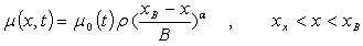 | (5) |
 | (6) |
where B = xX-xB is the length of varying-value section. As can be seen from Figure 1, a linear absorption parameter is adopted in this paper, i.e. α = 1.The boundary condition on the wave-paddles, Γ1is obtained by the continuous of the normal velocities U(t) of the paddles and that of the fluid: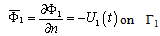 | (7) |
where n is the unit outward normal vector. U(t) can be express as the following form when simulating periodical waves: | (8) |
 | (9) |
where a is the transfer function,σis the angular frequency, ζ0 is the incident wave amplitude, k is the wave number, and h is the constant water depth.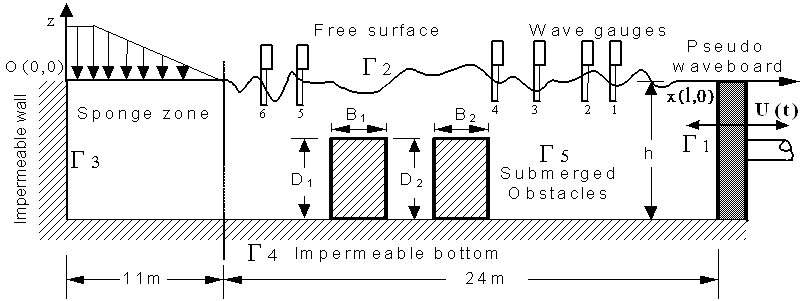 | Figure 1. Definition sketch for numerical wave flume comprises submerged obstacles |
The particle velocity is null in the normal direction on the impermeable wall,the bottom floor, and the submerged obstacles, the no-flow condition is therefore prescribed as: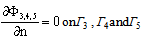 | (10) |
2.1.2. Integral Formulation and Boundary Discretization
According to Green’s second identity, the velocity potential Φ(x,z;t) within the region can be obtained by the velocity potential on the boundary, Φ(ξ,η;t), and its normal derivative, ∂Φ(ξ,η;t)/∂n, as: | (11) |

 The boundaries, Γ1 through Γ5, are divided into, respectively, N1 to N5 discrete linear elements, the smallest mesh sizes is adopted as Δx = 0.1h, where h is the water depth, as shown in Figure 2.
 | Figure 2. Definition sketch for discretization scheme |
To proceed with the calculation, Eq. (9) can be expressed in matrix form: | (12) |
[Φ] and are, respectively, the velocity potential, Φ(ξ,η;t), and its associated normal derivative, ∂Φ(ξ,η;t)/ ∂n. The coefficients of the matrix[O] are related to the geometric shapes of the boundaries. By differentiating the time derivatives through forward differencing, the position of nodes areregridded every time step, new positions of the nodes on free water surface, (xk+1,zk+1) can thus be obtained as:
 | (13) |
 | (14) |
The velocity potential on the free water surface at the successive time step, t=(k+1)Δt is given through: | (15) |
where s and n denote, respectively, the tangential and the normal direction. The normal derivatives on the boundaries Γ1, Γ3, Γ4 and Γ5, i.e.,  ,
,  ,
,  and
and  at t = (k+1)Δt can be obtained through Eqs. (7), (10) and (15). The unknown values, i.e. the normal derivative of the velocity potential on the water surface,
  ; the velocity potentials on the wave paddle,
  , the vertical wall,
  , the impermeable bottom,
  , and the impermeable submerged obstacles,
  , at the k-th time step can thus be obtained through Eq.(11), which can be written more compactly in a matrix form:
 | (16) |
I is the identity matrix. Detailed description concerning the iterative scheme of time stepping and computational procedures can be found in Chou & Shih (1996)[13][14].
2.2. Estimation of Current Velocity
The trajectory of water particles can be obtained by the current velocity at any position derived from the velocity potential Φ(ξ,η;t) and its normal derivative ∂Φ(ξ,η;t)/∂n on the boundaries, by Eq.(11), we obtain: | (17) |
 | (18) |
where M1 and M2 represent the interpolation functions of standard linear Lagrangianpolynomials using dimensional coordinates. The particle trajectory is obtained by linking each position of the nodes within the domain as: | (19) |
 | (20) |
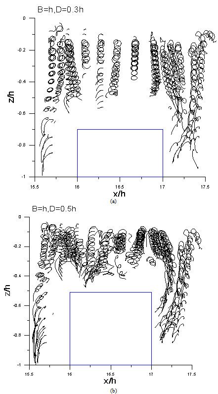 | Figure 3. Variations of particle trajectories of single breakwater with σ2h/g =0.5, B=1h (a)D=0.3h, (b)D=0.5h |
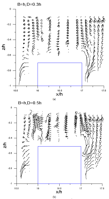 | Figure 4. Variations of particle trajectories of single breakwater with σ2h/g =1.0, B=1h (a)D=0.3h, (b)D=0.5h |
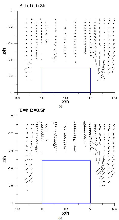 | Figure 5. Variations of particle trajectories of single breakwater with σ2h/g =1.5, B=1h (a)D=0.3h, (b)D=0.5h |
3. Resultsand Discussion
3.1. Trajectory AroundSingle Submerged Breakwater
Figures 3 to 5 shows, respectively, the cases for breakwater wide with B = 1h collocated breakwater height D = 0.3h and 0.5h. It can be seen that the trajectory of the water particles in the dimensionlessfrequency ofσ2h/g=0.5 is maximum,it can be seen apparently that the scope of wavy movement decreases when σ2h/g= 1.0, and the wave-length decreases when σ2h/g increase to 1.5, the characteristic of wave convert gradually from shallow-water wave (h<L/20) to deep-water wave (h>L/2), therefore, the activities of water particles in deeper water is implicit, except for those in the front of the submerged obstacle, which are slightly influenced. Accordingly, the movements of water particlesdecrease with the increasing of dimensionless frequency, waves are scarcely affected by the submerged breakwater due to the lower height of the embankment, and most of which passed through the submerged obstacle. When the breakwater height is fixed as D/h = 0.5, under the conditions of σ2h/g=0.5 and 1.0, due to the longer wavelengths, the water particles accelerate and speed-up through the top of the submerged breakwater (Figures 4 and 5).A small quantity of water particles above the breakwater no longer retained in a state of counter-clockwise rotation motion, but swift over the submerged breakwater in a curve instead.The formation of vortices in the front and rear of the submerged breakwater became more obvious,which rotate in an opposite direction against the progressive wave.When the dimensionless frequencyσ2h/g is equal to 1.5, because of theshorter wavelength, the physical activities of particle trajectoriesare significantly smaller.
3.2. Trajectory AroundSeries Submerged Breakwaters
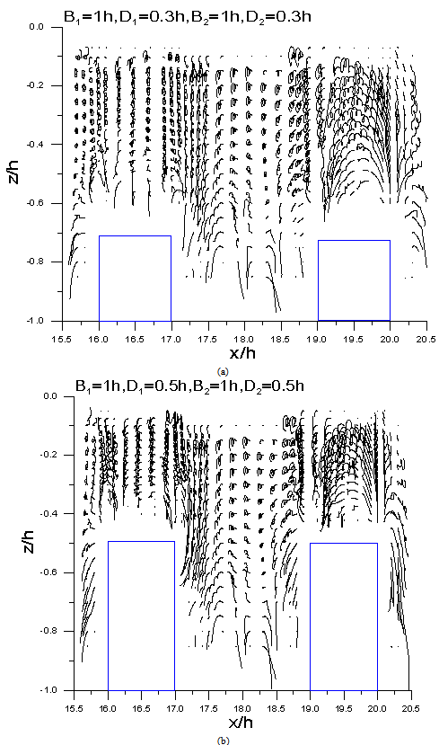
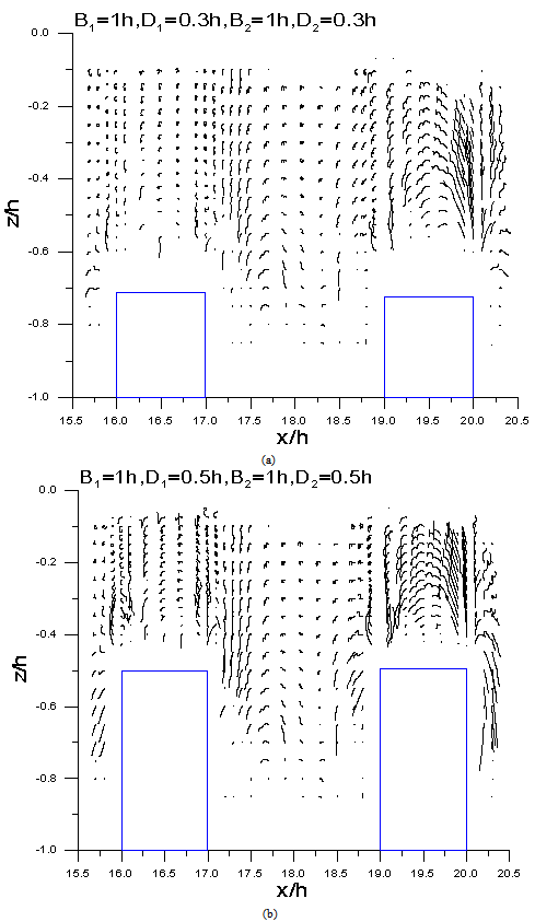
Figures 6 and 7 showed the variations of particle trajectories of a set of fixed double row submerged breakwater with width B= 1h and heightD = 0.5h,and the dimensionless frequencies are σ2h/g =0.5and σ2h/g =1.0, respectively. As the breakwater height increases, the water particles speed-up and pass throughthe submerged breakwater, and when the waves pass through the second barrier, a vortex will occur instantly. It can clearly be seen in Figure 6 that eddies appearin front of both the first and second barrier. In Figure 7, when the dimensionless frequency is increased from σ2h/g=0.5 to 1.0, the shortened in wave period hasdiminishedthe trajectory of the water molecules as the motion of vortex is abridged. Whenσ2h/g= 1.5 (Figure 8), this phenomenon is more apparently shown, and also because of the relatively shorter wavelength, as wave characteristics gradually turned to deep water wave, the activities of the water particles is therefore less obvious, and are slightly affected only in the front of the submerged breakwater. Accordingly, it is confirmed that when the dimensionless frequency trends larger, the range and extent of the movement of water particles is progressively converged and the trajectories is relatively unapparent.
3.3. Flow Fields Around the Submerged Breakwater
Figure 9 shows the distribution of velocity field when σ2h / g = 0.5, dike width B= h, embankment height D = 0.7h. As can be seen in the figure when t = 1/10 T, namely when the wave crest just come into contact with the submerged breakwater, andgradually after the wave-crest passed through the submerged breakwater, an eddy current rotates contrarily with the direction of the progressive waves was detected on the upper region in front and behind the submerged breakwater. Nevertheless, when the dimensionless frequency increases from σ2h/g = 0.5 to 1.0 or 1.5, the decreasing of wave period diminished the trajectory of water particles, hence, the activities and velocity field caused by the movement of water molecules are therefore slighter than that ofσ2h/g = 0.5. In Figure 9, a slight swirl generating in the front and rear side of the breakwater can be found when thetime is between t = 8/10T to 1T. Under thearrangementof double-row submerged breakwaters with width B1 = B2 = 1h, and when σ2h/g = 0.5, the variation in the distribution of velocity field had the same phenomenon as that demonstrated in Figure 6 to 8. Vortex occurs around the top of the submerged breakwater near the direction of the wave-generator, and cause chaos phenomenon to the water particles; furthermore, the existence of eddy current as well appears apparently above the submerged breakwater near the vertical wall, and in the middle of the two submerged breakwaters. Similarly, under the conditions of double breakwaters with B1 = B2 = 1h, when σ2h/g = 1.0, according to the distribution diagram of the velocity field, vortices occurred even more apparentabove the submerged breakwater on the wave-generator side, the water particles around the upper region of the submerged breakwaterexists a more conspicuousclutter phenomenon, also found that the vortex occurs above the submerged breakwater on the vertical impermeable wall side. Distinguishable vortex formation is also found simultaneously in the folder area between the middle of the two submerged breakwaters.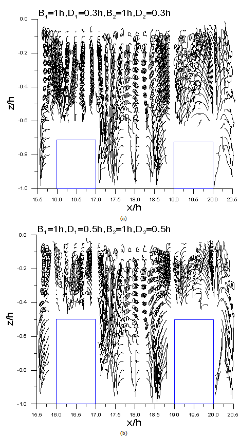 | Figure 6. Variations of particle trajectories of double row submerged breakwater with σ2h/g =0.5, B1= B2=1h(a)D=0.3h, (b)D=0.5h |
 | Figure 7. Variations of particle trajectories of double row submerged breakwater with σ2h/g =1.0, B1= B2=1h(a)D=0.3h, (b)D=0.5h |
 | Figure 8. Variations of particle trajectories of double row submerged breakwater with σ2h/g =1.5, B1= B2=1h(a)D=0.3h, (b)D=0.5h |
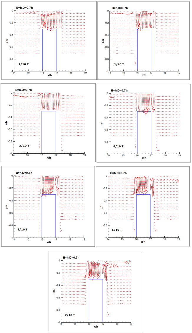 | Figure 9. Variation of velocity fields (σ2h/g =0.5,B=1h,D=0.7h) |
4. Conclusions
In this study, the boundary element method is adopted to simulate the velocity field of regular waves propagating over a series of submerged breakwater,and the variations of trajectoriesof the surrounding water particles. The discrepancy and the variations of physical characteristics are discussed by taking advantage of the trajectory diagram and the distribution of velocity field, and with the combination of different heightD and width of the submerged breakwatersB, collocated with different conditions of dimensionless frequencyσ2h/g. This study presents the following conclusions.(1). From the variation of particle trajectory, the motion of water particles in the circumference of the breakwater were interlaced in a disorganized circumstances,particularlywhen the frequency is smaller (longer periodT) with higher submerged breakwater height, this phenomenon was originated by the impact of eddy current.(2). The breakwater heightDand the dimensionless frequencyσ2h/g, has various gradations of impact on the occurrence of vortex.When the breakwater height is larger, with a smaller dimensionless frequency (i.e., longer wave-period),due to the longer wavelengthL, as well as the relative water depthh, the wave characteristics are tend to shallow water wave.When the submerged breakwater gets higher, the wavelength and 'water depth ratio' above the breakwater becomes even greater, andthe impact of the submerged breakwater is also relatively larger,the vortex will be obviously accrued in the front and rear side of the embankment angle.(3). When a single submerged breakwater is modified to multiple or series (double-row) submerged breakwaters, in addition to both the corners of the breakwater near the wave generator and the other near the vertical wall, the occurrence of eddy currents are also found in the middle area between the two submerged breakwaters.The main impact-factors for the intensity of the eddy current are the dimensions of progressive waves and the height of the submerged breakwaters, and are proportionally relationshipped.(4). This study investigatesthe affections of a series of submerged obstacleson wave fluctuation and the variation of velocity field.The physical phenomena of wave propagating over a series of submerged obstacles are effectively simulated.However, for the application of the present numerical model to the modification of the velocity distribution with obstacles, the results revealed that the error is relatively large near each boundary, and in particular, the velocity fields near the impermeable bottom. The error problems are to be solved in further study, a more efficient way will be investigate to effectively reduce these errors, and to make the results more accurate. Furthermore, proceed the present algorithm to the simulation of irregular random waves, and investigate the variation and/or distribution of the particle trajectory and velocity field under the influence of series submerged obstacles by irregular waves.
ACKNOWLEDGEMENTS
The authors wish to express their gratitude for the financial aids of the National Science Council, Republic of China, Project No. NSC-97-2221-E-236-011.
References
| [1] | Ting, F.C.K., Kim, Y.K., 1994, Vortex generation in water waves propagating over a submerged obstacle, Coastal Engineering, vol.24, pp.23-49. |
| [2] | Ohyama, T. and Nadaoka, K., 1994, Transformation of a nonlinear wave train passing over a submerged shelf without breaking, Coastal Engineering, Vol.24, pp. 1-22. |
| [3] | Balzano, A., Dessì, B. and Querzoli, G., 2002, Turbulence and mixing around a submerged obstacle subject to regular waves, Proceedings of the 11th Intl. Symposium on Appl. Of Laser Techniques to Fluid Mechanics. |
| [4] | Huang, J.H., Dong, C.M., 1999, Wave deformation and vortex generation in water waves propagating over a submerged dike, Coastal Engineering,vol. 37.pp.123-148. |
| [5] | Jung, K.H., Chang, K.A.& Huang, E.T.,2005, Two-dimensional flow characteristics of wave interactions with a free-rolling rectangular structure,Ocean Engineering, vol.32, pp.1-20. |
| [6] | Lo, D.C. and Young, D.L.,2004,Arbitrary Lagrangian–Eulerian finite element analysis of free surface flow using a velocity–vorticity formulation,Journal of Computational Physics,vol.195, pp.175-201. |
| [7] | Sue, Y.C., Chern, M.J., and Hwang, R.R., 2005, Interaction of nonlinear progressive viscous waves with a submerged obstacle, Ocean Engineering,vol.32, pp.893-923. |
| [8] | Rambabu, A.C. and Mani, J.S., 2005, Numerical prediction of performance of submerged breakwaters, Ocean Engineering, vol.32, pp.1235-1246. |
| [9] | Shen, L., and Chan, E.S., 2011, Numerical simulation of nonlinear dispersive waves propagating over a submerged bar by IB-VOF model, Ocean Engineering,vol.38, pp.319-328. |
| [10] | Zaman, M.H. and Baddour, E., 2011, Interaction of waves with non-colinear currents, Ocean Engineering,vol.38, pp.541-549. |
| [11] | Lin, M.Y. and Huang L.H., 2012, Numerical simulation of wave-structure interaction using a Lagrangian vortex method, Ocean Engineering, vol.44, pp.11-22. |
| [12] | Hsu, T.J., Sakakiyama, T. & Liu, P.L.F.,2002,A numerical model for wave motions and turbulence flows in front of a composite breakwater,Coastal Engineering,vol.46, pp.25-50. |
| [13] | Chou, C. R., Shih, R. S., 1996,Numerical generation and propagation of periodical wave in time domain, Coastal Engineering in Japan, vol.39, No. 2, pp.111-127. |
| [14] | Chou, C. R., Shih, R. S., 1996, Generation and deformation of solitary waves, China Ocean Engineering,vol.10, No. 4, pp.419-432. |
 Abstract
 Reference
 Full-Text PDF
 Full-text HTML