Kambiz Tahzibi 1, Mehdi Nasiri 2, Bijan Mashoof 3, Shokrollah Lotfi 4
1Mining Department, AZMA Rock and Tunnel Engineers Limited (AZMArte), Tehran, Iran
2Mining Department, Sound Mining Solution (SMS), Johannesburg, South Africa
3Civil department, AZMA Rock and Tunnel Engineers Limited (AZMArte), Tehran, Iran
4Mining Engineer, Abnieh-Ma’dan, Tehran, Iran
Correspondence to: Kambiz Tahzibi , Mining Department, AZMA Rock and Tunnel Engineers Limited (AZMArte), Tehran, Iran.
| Email: |  |
Copyright © 2016 Scientific & Academic Publishing. All Rights Reserved.
This work is licensed under the Creative Commons Attribution International License (CC BY).
http://creativecommons.org/licenses/by/4.0/

Abstract
The use of backfill in underground mines is increasing due to the need to achieve maximum ore recovery and to maintain the stability of underground excavations. The mechanical response of the backfill in narrow openings is significantly influenced by its interaction with the surrounding rock mass. This paper discusses the compressive strength required for cemented backfill used in mine backfilling and the method which is to be applied in VENARCH Manganese Mine in Iran. The minimum required compressive strength of the backfill is determined by the analyses results and the loader weight operating in the mine. The magnitude and distribution of the major principal stress contours demonstrate that the required uniaxial or unconfined compressive strength (UCS) of the backfill materials would need to be at least 1MPa. Cognisance of this requirement, together with the laboratory test results, demonstrates the need for a cemented backfill mix. Moreover, the mixture should have an appropriate level of rheological properties and sufficient compressive strength to meet the anticipated static and dynamic loads, while minimising the overall execution cost. This paper deals with the design of a Low Cement Content High Workability Concrete (denoted as LCHWC) mix, which is aimed at meeting the requirements.
Keywords:
Numerical modelling, Cemented backfill, Workability, Pumpability, Cut and fill
Cite this paper: Kambiz Tahzibi , Mehdi Nasiri , Bijan Mashoof , Shokrollah Lotfi , Experimental and Analytical Studies to Achieve an Optimised Cemented Backfill Mix to be Used in a Cut-Fill Mining Method, International Journal of Mining Engineering and Mineral Processing , Vol. 5 No. 1, 2016, pp. 1-8. doi: 10.5923/j.mining.20160501.01.
1. Introduction
The use of Cemented Paste Backfill (CPB) is an important part of underground mining operations in many cut-and-fill mines. Its application is on the increase and tends to become a standard practice throughout the world [1]. The most essential filling component in CPB is mill tailing, the waste material from the mine’s ore-processing plant. However, if mill tailing is lacked, while cheap aggregates are available, an appropriate low cement content concrete mix can be made as a substitute for the CPB.The greatest challenge in using low cement content concrete is to make a mix with high workability and pumpability. The low cement content decreases the viscosity of the mix, increasing the probability of its aggregates to segregate, causing plugging during concrete pouring. Increasing the volume of water in the mix achieves high workability, reduces viscosity and results in aggregate segregation. Adding Viscosity Modifying Agents (VMA) can solve this problem to some extent [2], but increases the cost of making the concrete mix.The aim of this research has been to design an optimised concrete mix with emphasis on two important properties:(i) Low cement content;(ii) High workability.Hence, the designed mix is referred to as LCHWC.The minimum compressive strength required for concrete was determined by modelling the backfilled mass concrete, using FLAC3D program. Various concrete mix samples composed of differing proportions of the available ingredients were then made and tested to achieve an optimised cemented backfill with appropriate level of rheological properties.
2. VENARCH Mine
The VENARCH manganese mine is located near a village of the same name in Qom Province, about 150km south of Tehran, Iran. Being the largest underground manganese mine in the country. The total geological manganese reserve is approximately 8Mt. The on-going mining operation covers an area of 200m x 120m, with an open pit which is 60m below ground level (1,475masl). Figure 1 shows the wire diagram of the 3-D model of the mine mass, which is approximately 750m long and extends in a NW-SE direction with a dip toward north-east. The average thickness of the outcrop is 80m.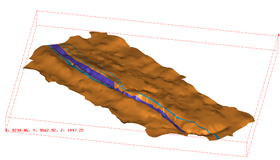 | Figure 1. Surface geology of VENARCH Mine, shown as a wire diagram 3-D model (Viewing north) |
3. Compressive Strength Required for the LCHWC
The compressive strength required for the backfill material depends upon the function it is intended for. If the fill is to be used as a ground support, its required uniaxial or unconfined compressive strength (UCS) should be at least 5MPa. If it is to be free-standing, its UCS can typically be lower than 1MPa. Previous operations indicate that the UCS of the fill mass can range between 0.2MPa and 5MPa, while the UCS of the surrounding rock mass is between 5MPa and 240MPa [3].
3.1. Hardened Backfilled Concrete as a Vertical Support
The mechanical effects of the fill are different from those of the primary ore pillars. Researches and in situ tests have shown that the fill is incapable of supporting the total weight of overburden (σv), and acts only as a secondary support system. The fill rigidity can range from 0.1GPa to 1.2GPa, while the surrounding rock mass rigidity varies from 20GPa to 100GPa [4]. As discussed by Donavan [4], it is possible to assume that any vertical loading will be the result of roof deformation (Figure 2), and that the design value of the UCS can be estimated by the following relation: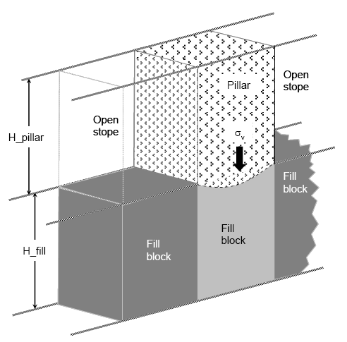 | Figure 2. Schematic representation of vertical loading of a pillar on the fill mass [3] |
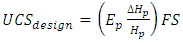 | (1) |
Where: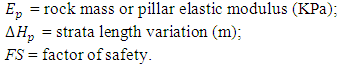 When the stope walls deform before backfilling, the maximum load will probably never reach the total weight of the deformed overlying strata [5]. In that case, the design UCS can be estimated by the following relation:
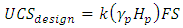 | (2) |
Where:k = scaling constant (must vary from 0.25 to 0.50);γp = strata unit weight (kN/m3);Hp = strata height below surface (m);FS = factor of safety.Given the complexity of the region’s geometry and the extraction procedure, a numerical model was made using FLAC3D software [6], which is proven to give accurate and reliable results. The required stiffness or compressive strength of the LCHWC was determined by analysing the model in order to prevent the fill block failure, which would occur due to the extraction from the second slice (Figure 3).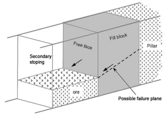 | Figure 3. Fill block failure mechanism during secondary stope mining [3] |
4. Numerical Model
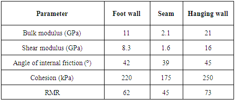
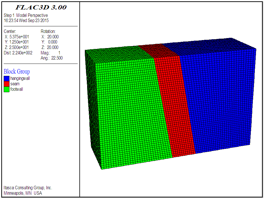
The dimensions of the model are: 25m width, 90m length, and 50m height. The model consisted of 90,000 elements and 96,798 grid points (Figure 4). The top and bottom of the model are restrained vertically (deep underground state was assumed); whereas the sides of the model are restrained perpendicular to each side [7]. Mohr-Coulomb elasto-plastic constitutive relation for both rock and concrete backfill is applied. Table 1 shows the mechanical properties of the rocks used in the numerical analyses.Table 1. Mechanical properties of the rocks used in the analyses
 |
| |
|
 | Figure 4. FLAC3D numerical model |
Having defined the constitutive relations and the material properties, and assigned the boundary conditions and the initial state, the analysis of the model is run until an equilibrium stage is reached. When a satisfactory response is obtained of the model, the formulation of the sliced cut-and-fill mine is conducted by stage construction.
4.1. Concrete Parameters
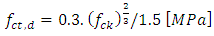
The backfilling concrete is characterised as having an elasto-plastic behaviour for which the Mohr-Coulomb drained material model can be used. As discussed by Ardiaca [8], the elastic modulus (E), cohesive strength and angle of internal friction of concrete can be estimated by the following relations: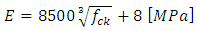 | (3) |
 | (4) |
 | (5) |
 | (6) |
Where: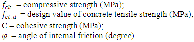 The coefficients
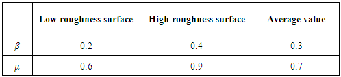
  depend on the roughness of the joint surface (Table 2).
Table 2. Values of
 (adopted from Ardiaca, 2009) (adopted from Ardiaca, 2009)
 |
| |
|
4.2. Analysis
A schematic of the multi-slice cut-and-fill mining method is depicted in Figure 5, with respect to this method; ore to be mined from stope A in a series of horizontal slices height of one meter, after each slice is removed backfill is placed into the stope using concrete, creating sufficient working platform to extract ore for the next slice. After six slices have been mined out, extraction of stope B can be started. A concrete pillar will be formed by filling the mined portioned would act as a retaining wall stabilising for stope B.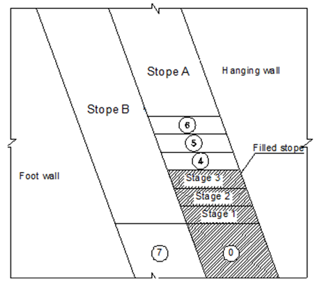 | Figure 5. Schematic diagram of the proposed extraction sequences |
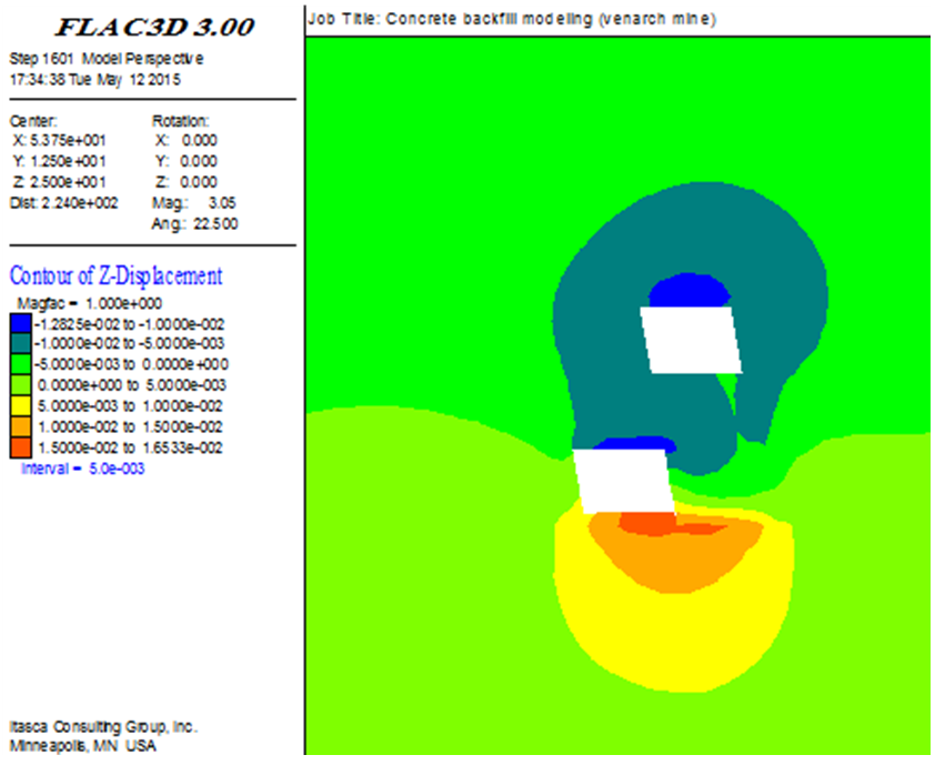
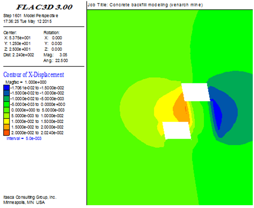
The analysis results are shown in Figure 6. Figure 6a shows the failure zones around the opening. Figures 6c and 6d show contours of the vertical and horizontal displacements. A small displacement of about 1 to 2 cm around the openings shows that there are no significant problems in the roof and wall.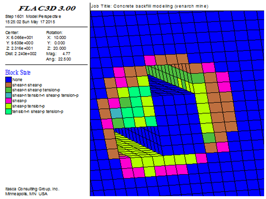 | Figure 6a. Failure state after developing the second slice |
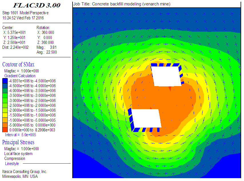 | Figure 6b. Principal stresses vectors and contours of SMax after developing the second slice |
 | Figure 6c. X-displacement after developing the second slice |
 | Figure 6d. Z-displacement after developing the second slice |
The analysis results indicate that the mass concrete wall, shown in Figure 3, is in a stable condition, although partial failures occurred in the vicinity of the production area. Principal stresses vectors and contours of SMax were shown in Figure 6b, from which it is deducted that the stress state is compressive. Considering that the minimum compressive strength of the backfill concrete is required to be 1 MPa, the failure index - ratio of backfill compressive strength to maximum principal stress - is higher than 1. Hence, given that the concrete contact pressure (sc) is equal to 0.3fc, the characteristic compressive strength (fc) can be calculated as around 3 MPa.
5. Vehicle Load
Other factors used in determining the minimum required fc of the backfill concrete are the vehicle load and the bearing capacity of the placed concrete. 5 – 7 days after backfilling, the bearing capacity of set concrete should be sufficient to carry the weight of a 5t CAVO310 rubber tyre wheel loader (Figure 7). The contact width (B) of each wheel of the loader is determined by the following relation [9]: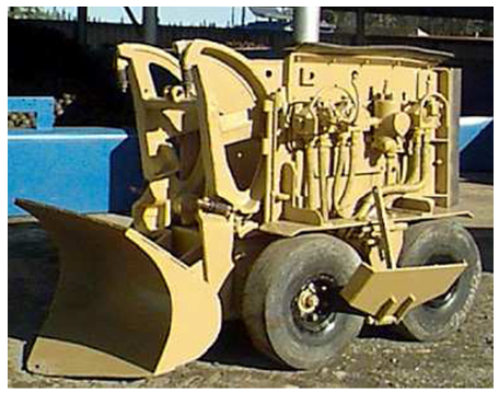 | Figure 7. A CAVO310 loader |
 | (7) |
Where Ft = each tire load = 12.5 kN, and p = tire air pressure = 448 kN/m2.Using the above formula, the loader wheel contact width is calculated as about 17 cm. By applying this estimate and the tire width (16 cm), the contact pressure  on the concrete mass is found to be approximately 0.46 MPa. The seven-day compressive strength (fc = sc/0.3) is therefore calculated as about 1.53 MPa. Based on credible concrete standards, an increase factor of 1.5 gives the mean (28-day) value of compressive strength (fcm) as 2.29 MPa.The higher of the two values obtained for the minimum required fc, i.e 3 MPa, is chosen, from which the value of mean compressive strength (fcm) is calculated to be 4 MPa. The value of fcm is used for designing the concrete mix.
6. Concrete Mix Design
The main properties of LCHWC mix should be the same as those of self-compacting concrete (SCC), which is different from conventional concrete. The characteristics of fresh concrete mix are defined by such important properties as flowability, workability, segregation resistance, and open time [10], which determine whether or not the mix can be placed satisfactorily. These properties need to be carefully controlled using appropriate tests. The procedure for designing a concrete mix is shown in Figure 8.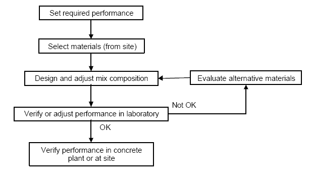 | Figure 8. Procedure of concrete mix design |
6.1. Resulting Mix Design
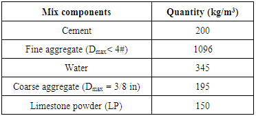
In this investigation, the cement content was kept at a constant value of 200 kg/m3. Limestone, which is locally available in the area, was powdered and then added to cement in quantities of 50-350 kg for each cubic metre of the mix. It is worth mentioning that utilising limestone powder (LP) improves the rheological characteristic of the mix [11] and [12]. Each concrete mix was then tested to study the variation of workability. The proportions of the ingredients of an optimised LCHWC mixture design are shown in Table 3.Table 3. Mix proportions of LCHWC
 |
| |
|
The grading graphs for the aggregates are shown in Figure 9. Aggregates with grading within Zone 2 result in mixes with higher pumpability. Curve B9.5 represents the aggregates of smaller than 10mm available in the VENARCH borrow area.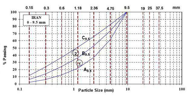 | Figure 9. Fine and coarse aggregates grading (max. grain size 9.5mm) |
6.2. Fresh Mix Properties
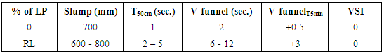
The workability of the LCHWC mixes with different proportions of limestone powder (LP) was determined by conducting slump flow, T50cm slump flow, V-funnel, V-funnelT5min., and VSI tests [10]. The result for the optimum mixture is presented in Table 4 and figure 10.Table 4. Properties of fresh LCHWC mix containing limestone powder
 |
| |
|
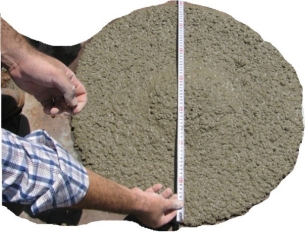 | Figure 10. Slump measurement of LCHWC |
The results of the VSI and V-funnelT5min tests show that the concrete mix obtained is quite homogenised. Because of its adequate viscosity, the probability of segregation of the mix along the course of pumping is low [13]. The resulted values of V-funnel and T50cm shown in Table 4 are less than the minimum allowable values for self-compacting concrete (SCC), which is used in bridges, tunnels, etc. The resulted values indicate a higher workability, which is an important requirement for the ease of backfilling. The higher W/C ratio of the mix is an indication of its lower compressive strength (fc), but the reduced value of fc is within the acceptable limit for backfill concrete.
7. Conclusions
This paper is the result of a study aimed at designing a pumpable concrete mix to be used with ease for filling the openings left in the VENARCH Manganese Mine, Iran. The main objective of the investigation was therefore to achieve an economically and practically optimised concrete mix.It costs less to produce this concrete mix - denoted as LCHWC in this paper -than the universally used Cemented Paste Backfill (CPB); making it an alternative to the CPB. The analysis of a numerical model of the multi-slice, cut-and-fill mining method shows that the minimum required compressive strength of the filling mix is 3 MPa. This low compressive strength is an advantage, for less cement is needed in the mix, making it cheaper to produce. However, decreasing the cement content of the mix reduces its viscosity, which can be remedied by adding limestone powder (LP). Fortunately, adequate amount of LP can be provided due to the abundance of limestone in the area.The main criteria for the design are high flowability and adequate viscosity. A number of tests were carried out in order to achieve an optimum mix design based on these criteria. The tests results have shown that the backfill concrete mix made with unwashed sand from the nearby borrow site and at least 150 kg/m3 of powdered limestone can be pumped through long routes without any segregation and/or bleeding problems, which can clog the pipes. Also, the hardened concrete is found to have the required engineering properties.The other advantage of using concrete mix for backfilling instead of stowing the openings with waste materials is the formation of concrete pillars which act as retaining walls, stabilising the adjacent stopes. Thus, miners are able to extract more ore, and the extraction productivity increases remarkably to almost 100%. The overall productivity of the mine is also increased by 30%.
References
| [1] | Pengyu, Y. and Li, L. (2015). "Investigation of the short-term stressdistribution in stopes and drifts backfilled with cemented paste backfill." International Journal of Mining Science and Technology, Vol. 25 (Issue No. 5), pp. 721-728. |
| [2] | Ramachandran, V., 2013. Concrete Admixture Handbook Properties, Science, and Technologh. 2nd ed. s.l.:Ada lonescu. |
| [3] | Belem, T. & Benzaazoua, M., 2004. An overview on the use of paste backfill technology as a ground support method in cut-and-fill mines. London, Tayler & Francis Group, pp. 637-650. |
| [4] | Belem, T. & Benzaazoua, M., 2008. Design and Application of Underground Mine Paste Backfill Technology. Geotechnical and Geological Engineering, 26(2), pp. 147-174. |
| [5] | Donavan J.G., 1999. The effects of backfilling on ground control and recovery in thin-seam coal mining. M.Sc. Thesis, Virginia Polytechnic Institute and State University, Blacksburg, Virginia, 148 p. |
| [6] | Itasca, 2002. FLAC-Fast Lagrangian Analysis of Continua, User's Guide. Itasca Consulting Group. |
| [7] | Zarlin, N., Sasaoka, T., Shimada, H. & Matsui, K., 2012. Numerical study on an applicable underground mining method for soft extra-thick coal seams in Thailand. Science Research Engineering, Volume 4, pp. 739-745. |
| [8] | Ardiaca, D. H., 2009. Mohr-Coulomb parameters for modelling of concrete structures. Plaxis Bulletin. |
| [9] | Hassani, F. & Quellet, J., n.d. Sustainability and development of paste fill technology “Mining and Sustainable Development” 20th World Mining Congress & Expo 2005, 7 – 11 November, Tehran, Iran, pp. 33-42. |
| [10] | EFNARC, 2002. Specification and guidelines for self-compacting concrete. Tech. Rep., p. 2002. |
| [11] | Beeralingegowda, B. & Gundakalle, V., 2013. The effect of the addition of limestone powder on the properties of self-compacting concrete. International Journal of Innovative Research in Science, Engineering and Technology, Vol. 2(Issue 9). |
| [12] | Uysal, M. & Yilmaz, K., 2011. Effect of mineral admixtures on properties of self-compacting concrete. Cement & Concrete Composites, pp. 771-776. |
| [13] | Khatib, R., 2013. Analysis and prediction of pumping characteristics of high-strength self-consolidating concrete. PhD. Thesis, UNIVERSITE DE SHERBROOKE, Canada. |

 Abstract
 Reference
 Full-Text PDF
 Full-text HTML