Dilip Makhija, A. K. Mukherjee, Tamal Kanti Ghosh
Research and Development Division, Tata Steel Limited, Jamshedpur
Correspondence to: Dilip Makhija, Research and Development Division, Tata Steel Limited, Jamshedpur.
| Email: |  |
Copyright © 2012 Scientific & Academic Publishing. All Rights Reserved.
Abstract
The banded iron formation of Banded Hematite Jasper is a very low grade iron ore that usually contains Fe in the range of 30-40% depending on the origin. Banded hematite Jasper obtained from Barbil region of India and assaying 41.9% Fe, 38.4% SiO2 and 0.4% Al2O3 was studied for pre-concentration of iron values adopting Jigging and Dry High Intensity Magnetic Separation. The pre-concentration studies were carried out with representative BHJ sample crushed and sized to -10+0.5mm, -6+0.5mm and-3+0.5mm. The dry high intensity magnetic separation process could achieve a best possible iron recovery of 69.9% with 51.4%Fe in the concentrate. The Jigging process could achieve a maximum iron recovery of 68.5% with 57.3%Fe in concentrate. The optimum recoveries and grade in both the cases were obtained for a feed size of-3+0.5mm. The results indicate that Jigging is a better pre-concentration technique when compared to Dry High Intensity Magnetic Separation.
Keywords:
Banded Hematite Jasper, Pre-concentration, Jigging, Magnetic Separation
Cite this paper: Dilip Makhija, A. K. Mukherjee, Tamal Kanti Ghosh, Preconcentration Feasibility of Gravity and Magnetic Techniques for Banded Hematite Jasper, International Journal of Mining Engineering and Mineral Processing , Vol. 2 No. 1, 2013, pp. 8-15. doi: 10.5923/j.mining.20130201.02.
1. Introduction
Most of the Iron ore processing plants in India are designed to utilize ROM Iron ores of Fe ≥63% to produce lump and fines product suitable for Blast furnace/Sintering. With the availability of high-grade iron ores and for the economic reasons, a simple washing scheme is being industrially practiced for beneficiation of the iron ores (Nayak N.P et al;2012). The conventional crushing, washing and screening, classification and solid-liquid separation units are incapable to enrich low grade Iron ores like Banded Hematite Jasper (BHJ) and Banded Hematite Quartz (BHQ). Banded iron formation is a sedimentary rock that was commonly deposited during the Precambrian.It was probably laid down as a colloidal iron-rich chemical precipitate, but in its present compacted form it consists typically of equal proportions of iron oxides (hematite or magnetite) and silica in the finely crystalline form of quartz known as Chert. Banding is produced by the concentration of these two chemical components into layers about1– 40mm thick; typical banded iron formation consists of pale silica-rich cherty bands alternating with black to dark red iron-rich bands. These contrasting layers are sharply defined, so that the rock has a striped appearance; banded iron formation is normally a hard, tough rock, highly resistant both to erosion and to breaking with a hammer. The most probable source for the bulk of the iron and silica in the banded iron formations was hot magmatic waters and vapours ejected under submarine conditions whereas the banded structure was due to rhythmic precipitation of iron and silica(Percival, F.C, 1931). The huge iron ore deposits of Jharkhand–Orissa region, eastern India are partof the volcano-sedimentary basins containing ironand to some extent manganese deposits of Precambrianage (Jones, H.C, 1934; Roy, S and Venkatesh, A.S, 2009).Various workers fromtime to time studied on different aspects of BIFand iron ores of eastern India (Jones, H.C, 1934; Dunn, J.A, 1935; Banerji, A.K, 1977; Chakraborty, K.L and Majumder, T, 2002; Roy, S and Venkatesh, A.S, 2009). The origin and the band formation in Banded iron formations as proposed by (Dunn,J.A, 1935)is due to the secondary silicification of altered tuffs and phyllites along bedding planes.The process of beneficiation of such lean grade ores is dependent on the variation in physical, chemical and mineralogical properties between constituent minerals and their grain sizes(Nayak, N.P et al,2012). Therefore a scientific and research assisted selection of unit operations is required to optimize iron grade and recovery. The gangue and ore minerals contained in Banded Hematite Jasper vary significantly in their physical properties i.e magnetic and gravity properties. Therefore gravity and magnetic separation techniques are the potential low cost techniques that can be applied to pre-concentrate or beneficiate such ores. The fine size of the ore and gangue minerals and their poor liberation is however one of the constraint that limits its beneficiation at coarser stage. Pre-concentration of iron values at coarser stage of flow-sheet development enables rejection of substantial quantity of gangue mineral thereby reducing the load ongrinding mill. This paper details out the attempts made to pre-concentrate BHJ ore and compares the performance of Jigging and Dry Magnetic separation techniques of pre-concentration.
2. Experimental Studies
2.1. Material
BHJ sample was collected from Barbil region of eastern India. The Ore Geology of this region is a part of the Precambrian Meta Sedimentary rocks of Eastern India.The physical appearance of BHJ sample shows alternating bands of Hematite and Jasperwith intermittent bands of shale. The bands vary in colour from black, brown, grey to Jasper red with complex interlocking of ore and gangue minerals.
2.2. Characterization
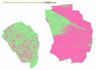 | Figure 1. Massive hematite and quartz bodies |
Ore characterization reveals the information on physical, chemical and mineralogical properties of ores. The preliminary information on ore mineralogy that includes qualitative mineral analysis, structural and textural mineral phase analyses, size and shape of the minerals and ore mineral liberation analysis together with chemical analysis form the basis for pre-selecting beneficiation process.The mineral bands vary in their width from 0.2mm to a maximum of 11mm. Intercalations of Jasper and Shaly layers/bands are clearly demarcated by their color tinge variation and mineral content. On an average about 98% of the area is occupied by hematite and quartz, the remaining being occupied by goethite, limonite and kaolinite. The individual contribution of hematite is about 56% and that of quartz is about 42%. Figure 1 to Figure 4 shows the QEMSCAN pictures of different BHJ-ROM samples. Figure 1 shows that presence of both quartz and hematite as massive ore bodies. Figure 2 shows alternate banding of quartz and hematite with band width varying from 0.2mm to 11mm. Figure 3 shows the presence of inclusions of ultrafine quartz and hematite grains within hematite and quartz bodies respectively. The textural relationship shown in Figure 3 and 4 suggests a very complex relationship between quartz and hematite. The presence of ultrafine grains of quartz and hematite within the ore and gangue mineral bodies indicates that the BHJ sample is very difficult to beneficiate even at very fine grind size.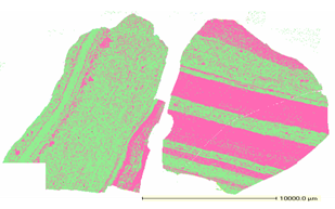 | Figure 2. Alternate bands of hematite and quartz |
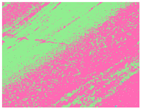 | Figure 3. Detailed textural image of BHJ |
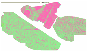 | Figure 4. Thin veins of quartz in BHJ |
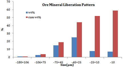
The mineral liberation analysis carried out with a ground sample of size less than 150µm shows that the size of liberated ore mineral size varies from 2 to 125 µm in which about 73% of the ore mineral particles occur in the size range of 10-75µm. The size of gangue mineral quartz varies from 15 to 140 µm. It is observed that about 80% of the hematite grains contain inclusions of quartz. Similarly about 60% of the quartz contains hematite inclusions. The overall ore mineral size and liberation pattern is shown in Figure 5& Figure 6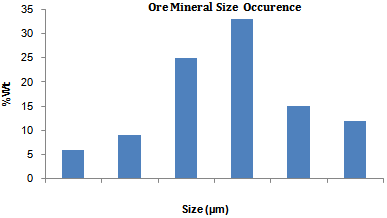 | Figure 5. Ore Mineral (Hematite) Size occurrence in BHJ |
 | Figure 6. Ore Mineral (Hematite) Liberation Pattern in BHJ |
 | Figure 7. Size-wise Fe and SiO2 distribution of BHJ crushed to -10mm |
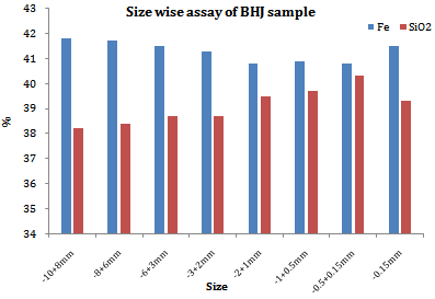
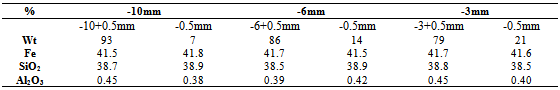
The mineral liberation analysis reveals that about 59% of the total ore mineral is liberated at a grind size of 150 microns (siliceous inclusions ignored). The un-liberated ore mineral locking varies from a minimum of 20% to a maximum of 70% with most of the ore mineral locking occurring in the size range of -150+75µm. On an average the degree of ore mineral locking is 45% which implies that 41% of the un-liberated ore mineral particles contain 45% siliceous impurity. Therefore concentrate recovered through any separation process (at 150 microns) whether Gravity or Magnetic will be able yield a product grade of 60.5% Fe considering a 100% recovery of iron units.The as-received BHJ sample which was subjected for detailed characterization studies analysed 41.5% Fe, 38.7% SiO2 and 0.4% Al2O3. The size-wise chemical analysis of as-received sample crushed to -10mm shown in Figure 7 shows that there is no definite trend of ore or gangue mineral segregation. The Fe as well as SiO2is almost uniformly distributed across all size fractions thus negating the possibility of beneficiation/enrichment of the sample through classification. It is also seen that size fraction -1+0.15mm shows comparatively higher proportion of gangue mineral SiO2. The higher presence of gangue can be attributed to preferential crushing of the BHJ at gangue mineral ore body which is an area of relatively weaker physical bonding. The crushing at gangue mineral body results in generation of gangue mineral fines which contribute mostly to -1+0.15mm fraction. The weight contribution of +0.5mm and-0.5mm fractions is 93% and 7% respectively.
2.3. Procedure
2.3.1. Gravity Separation
The BHJ sample was initially subjected to standard sampling procedure of coning and quartering to draw three representative samples. These three samples were then individually stage crushed to -10mm, -6mm and -3mm. The individual crushed samples were further screened at 0.5mm to obtain -10+0.5mm, -6+0.5mm and -3+0.5mm fractions that were eventually tested for pre-concentration feasibility. Each of the -10+0.5mm, -6+0.5mm and -3+0.5mm fractionswere further individually divided into two representative samples i.e. one for conducting Gravity separation and other for conducting Magnetic separation test. The chemical composition of samples is given in Table1Traditional mineral processing techniques become increasingly inefficient as particles sizes are reduced, resulting in unacceptable grades and/or recoveriesbelow certain size thresholds(Dobbins,M et al,2009). Therefore -0.5mm fraction of BHJ sample was screened out before conducting beneficiation studies. Gravity separation studies were conducted with -10+0.5mm, -6+0.5mm and -3+0.5mm to assess the feasibility of Jigging as a pre-concentration operation.Jigging is a gravity separation technique where bulk materials are separated into light and heavy density fractions (Das,B et al,2007). Even today it is the widespread technology in coal preparation because of its high separation precision, cost-effectiveness and high through put rate (Das, B et al,2007, Rong, X. R and Lyman, G.J, 1992). The tests were conducted in MINTEK Mineral Density Separator which is an advanced density separator for classifying ores into different density classes. The objective is to evaluate the efficiency or study the feasibility of Jigging and/or Dense media separation process.The unit is capable of treating material in the size range of 0.5mm to 30mm and density exceeding 4 which is otherwise possible only through heavy liquid separation. The prototype PLC controlled, pneumatically actuated MDS is shown in the Fig 5. This consists of maximum 5 rings which are clamped together to comprise the jig chamber. The number of rings can be custom fitted as per requirement. This is fitted to a water/air chamber or hutch where the air supply / exhaust are controlled with pneumatic valves from the PLC. The PLC controls the delay between strokes, the upstroke, holding and release times. The water supply is controlled with a rotameter and the manifold air supply pressure controlled by a manual pressure regulator.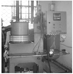 | Figure 8. MINTEK Mineral Density Separator |
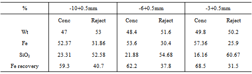
The test work yields information on yield, grade and density of different layers which are further analysed to assess the feasibility of Jigging as a beneficiationprocess. The results of one of the MDS tests conducted are shown in Table 2
2.3.2. Dry High Intensity Magnetic Separation
Magnetic separation equipment generally fall into three basic categories: low, medium and high intensity, based on the relative magnetic field strength employed to accomplish separation. Low intensity magnetic separators (LIMS) are commonly used for concentration of magnetite, or for separation of ferromagnetic materials(Dobbins, M et al,2009). Medium intensity magnetic separators are mostly rare-earth dry drum separators (RED) with applications in highly paramagnetic mineral such as chromite, ilmenite and garnet. High intensity magnetic separators may be wet or dry. High intensity dry magnetic separations are induced-roll (IRM) or rare-earth roll/drum (RER/RED) based magnetic separators.Table 1. Chemical composition of feed samples
 |
| |
|
Table 2. Mineral Density Separation results
 |
| |
|
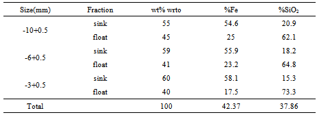
Table 3. Sink and Float results of BHJ samples at SG 3.6
 |
| |
|
 | Figure 9. G-R curve for Mineral Density Separator test |
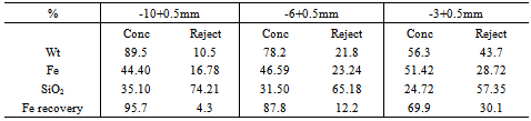
The dry RER magnetic separator is highly efficient for weakly magnetic minerals such as hematite, the only constrain being the top size of the ore that can be processed. RER magnetic separators are commonly employed in separating weakly magnetic materials from silica sand. The dry RER magnetic separators however suffer from the disadvantage they are unable to efficiently process fine ore minerals. Dry separation processes have been largely confined to the treatment of materials coarser than 75 µm (Read, A.D et al,1976). Therefore the BHJ sample was pre-screened to remove -0.5mm material to ensure better separation efficiency.The size fractions -10+0.5mm, -6+0.5mm and -3+0.5mm were separately tested in Dry High Intensity RER magnetic separator (hereafter referred as DHIMS) to study the feasibility of iron enrichment. The magnetic separator having an intensity of about 15000 gauss on the roll surface was used to separate magnetic from non-magnetics. It is seen from the results that concentrate grade increases with decrease in feed size. The iron recovery however shows a declining trend as the sample is crushed to lower sizes. The iron recovery of 95.7% at a feed size of -10+0.5mm decreases to 69.9% when the sample is crushed to -3mm. Similarly the concentrate grade increases by 7.02 % absolute from 44.40% Fe to 51.42% Fe at the same crushing ratio. The G-R curve in Figure 10shows that there is a sharp increase in concentrate grade with a simultaneous sharp drop in iron recovery at a grind size of -3mm.
3. Results and Discussion
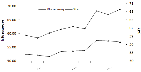
The grade-recovery (referred as G-R) curve of Mineral Density Separation shown in Figure 9 indicatesthat the recovery of ore minerals increases with decrease in feed size. Similarly the concentrate grade also shows an upward trend with a corresponding decrease in feed size. The increase in both recovery and grade with decreasing feed size suggests that the ore mineral is getting liberated even as the sample is crushed down from 10mm to 3mm which implies that there is a preferential crushing of ore mineral at the ore-gangue mineral grain boundary. The preferential crushing may be attributed to a weak physical bonding between ore and gangue minerals in comparison to ore-ore or gangue-gangue mineral. The observation corroborates the research work of (Garcia, D et al,Bradt, R.C et al, 1995 and Kawatra, S.K, 2006) that suggests that thesignificance of grain boundary fracture (preferential breakage) varies notonly with ore type but also with particle size.The iron recovery achieved through MDS shown in Table 2 varies from 59.3 % at -10+0.5mm to 68.5% at -3+0.5mm size fraction. Similarly the concentrate grade varies from 52.37% Fe at -10+0.5mm size to 57.4% Fe at -3+0.5mm size. The specific gravity of -3+0.5mm MDS concentrate as measured was found to be 3.65. Therefore Sink and Float tests were carried out with BHJ feed at a density of 3.6 to compare the performance of gravity separation unit against the theoretical yield. The sink and float tests revealed that a concentrate grade of 58.1% Fe is achievable for a feed size of -3mm with an iron recovery of 83.5%. In comparison the gravity separation test yielded a best concentrate gradewith 57.36% Fe and iron recovery of 68.5%. The concentrate grade achieved through MDS almost matches with the theoretical achievable gradewhile the recovery is about 82% of the theoretical achievable recovery. The dry high intensity magnetic separation of -3+0.5mm BHJ sample resulted in an iron recovery of 69.9% with a concentrate grade of 51.42% Fe. The G-R curve shown in Figure10 reveals that DHIMS has very poor enrichment efficiency at coarser size- 10+0.5mm. The enrichment efficiency gradually improves with crushing to finer size -3+0.5mm. 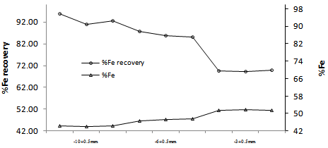 | Figure 10. G-R curve for Dry High Intensity magnetic Separation |
Table 4. Dry High Intensity Magnetic separation results
 |
| |
|
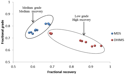 | Figure 11. Fractional Grade and Recovery of MDS and DHIMS |
The Figure 11 shows a comparative analysis of fractional grade and fractional recovery of DHIMS and MDS. The figure suggests that DHIMS has inferiorore mineral enrichment efficiency for all sizes whileMDS is having comparatively better ore mineral enrichment efficiency. The fractional grade and fractional recovery is calculated asFractional Grade = C/69.9*Fractional Recovery = (Yc*C) / (F*100)Where C = Concentrate Grade, Yc = Concentrate Yield, F = Feed Grade*Theoretical possible concentrate grade
4. Conclusions
The pre-concentration of iron values in Banded Hematite Jasper can be achieved through gravity and dry high intensity magnetic separation. The pre- concentration efficiency of both gravity and magnetic techniques increase with decrease in feed size. The Gravity Jigging process of pre- concentration yields better results in terms of grade enrichment and iron recovery efficiency. Both concentrate grade and recovery are seen increasing with corresponding decrease in feed size of the ore. The increase in both recovery and grade with decreasing feed size suggests a preferential crushing mechanism of ore mineral at the ore-gangue mineral grain boundary which corroborates with the earlier research work done on this subject. The ore pre- concentration is optimum at a feed size of -3+0.5mm. The grade and recovery obtained through Jigging at this size is 57.36% Fe and 68.5% respectively. The concentrate grade achieved through Gravity process almost matches with the theoretical grade of 58.1%Fe as obtained in Sink and Float test. The iron units’ recovery is 82% of the theoretical possible recovery.
References
| [1] | Banerji A K 1977. On the Precambrian banded iron formation and manganese ores of Singhbhum region, Eastern India.Economic Geology, 72, 90–98. |
| [2] | Bradt, R.C, Lin C.L, Miller J.D and Chi G 1995. Interfacial fracture of multiphase particles and its influence on liberation phenomenon. Minerals Engineering 8(4-5):359-366 |
| [3] | Chakraborty K L and Majumder T 2002. Some important aspects of the banded iron formation (BIF) of eastern Indian shield (Jharkhand and Orissa).Indian Journal of Geology, 74(1–4), 37–47. |
| [4] | Das B, Prakash S, Das S.K and Reddy P.S.R 2007, Effective Beneficiation of Low Grade Iron Ore Through Jigging Operation. Journal of Minerals & Materials Characterization & Engineering, Vol. 7, No.1, 27-37. |
| [5] | Dobbins M, Dunn P and Sherell I 2009. Recent advances in magnetic separator designs and applications. The 7th International Heavy Minerals Conference ‘What next’, The Southern African Institute of Mining and Metallurgy. |
| [6] | Dunn J A 1935. The origin of iron ores in Singhbhum, India. Economic Geology. 30 643–654. |
| [7] | Garcia D, Lin C.L, Miller J.D. Experimental Evaluation of a Mineral Exposure Model for Crushed Copper Ores. Advances in Comminution 261-268 |
| [8] | Jones H C 1934. The iron ore deposits of Bihar and Orissa. Geological Survey of India Memoir, 63, 1098–1109. |
| [9] | Kawatra S.K 2006. Advances in Comminution 261-268 |
| [10] | Nayak N.P, Das Abhimanyu and Pal B. K 2012. Feasibility of Beneficiation of Banded Hematite Jasper of Eastern India. International Journal of Engineering Research and Technology Vol.1 Issue 9 |
| [11] | Percival F.C 1931, The Iron ores of Noamundi, Singhbhum. Transactions of the Mining and Geological Institute of India 26(3), 169-271 |
| [12] | Read A .D, Whitehead A and Grainger-Allen T. J. N 1976.Pre-Treatment of Feed for Dry Magnetic Separation of fine materials.International Journal of Mineral Processing, 343—355 |
| [13] | Rong X Rui and Lyman Geofrrey J. 1992. The effect of jigging time and air cycle on bed stratification in a pilot scale Baum jig, Fuel, Vol 71, Issue 1, 115-123 |
| [14] | Roy Sand Venkatesh A. S 2009. Mineralogy andgeochemistry of banded iron formation and iron ores from eastern India with implications on their genesis. Journal of earth System Science, 6, 619-641 |
 Abstract
 Reference
 Full-Text PDF
 Full-text HTML