C. Raghukumar 1, Sunil Kumar Tripathy 2, S. Mohanan 1
1Raw Material and Iron Making Technology Group, Tata Steel Ltd., Jamshedpur, 831007, India
2Research and Development Department, Tata Steel Ltd., Jamshedpur, 831007, India
Correspondence to: C. Raghukumar , Raw Material and Iron Making Technology Group, Tata Steel Ltd., Jamshedpur, 831007, India.
| Email: |  |
Copyright © 2012 Scientific & Academic Publishing. All Rights Reserved.
Abstract
Beneficiation of high alumina iron ore fines from Noamundi, India is studied for producing sinter/ pellet grade concentrate. The iron ore fine sample has a feed grade of 59.77%Fe, %4.71SiO2, and % 5.89Al2O3 with % 5.53 of LOI (Loss on Ignition). From the characterisation studies, it is revealed that the sample contains huge quantity of goethite which is partially weathered, interlocked with hematite and gangue minerals like gibbsite, kaolinite and quartz at different proportions. Two conceptual flow sheets have considered for the beneficiation of Indian high alumina iron ore fines. The first option, consisting of hindered settling classifier followed by two stage gravity concentration results in a product quality with 66.82%Fe and 2.1%Al2O3 content ensuring 25.15% iron recovery. In the second option, the iron ore fines treating in the similar approach but the second stage gravity concentration replaced by magnetic separation results in a product quality with 67.77% Fe, 1.53% Al2O3 with 28.95% of iron recovery. Mineralogical studies revealed that the concentrate product quality depends on presence of the goethite in the product.
Keywords:
High alumina Iron Ore, Beneficiation, Floatex Density Separator, Gravity Concentration, Magnetic Separation
1. Introduction
The consumption of iron ore has increased rapidly over the past decade due to the tremendous growth of iron and steel industry. Iron making by blast furnace utilises different kinds of iron ore products as a feed such as lump (as a feed directly) and sinter/pellet which are the agglomerates of iron ore fines, both containing less than 2% alumina. The presence of highly friable hematite and lateritic ore results in generation of large quantity of fines during mechanized mining and crushing which are rich in Al2O3. During beneficiation/washing process, products which have alumina less than 2% are recovered as prime products (lump and sinter fines) and a fraction having size less than 0.15mm (150 microns) gets accumulated with high percentage of alumina (> 4% ), hence, this cannot be used in the blast furnace. This fraction is almost 15% of the total quantity of ore mined and is being dumped in tailing ponds/dams. If suitable application for the fines generated or the proper processing technology for the reduction of alumina is not found quickly, there is lurking danger to stop the mining activity due to lack of space to dump the same besides the environmental issues.It has been reported in the literature that by upgrading the ore fines using appropriate beneficiation techniques and utilizing this fraction in the sinter feed up to 40% by micro-balling of the sinter mix prior to sintering[1]. The management of tailings from iron ore mines is an important issue not only from an environmental point of view but also from resource conservation perspective[2]. Although several research initiatives have been taken up by different institutions to beneficiate this fraction with suitable techniques, a viable option for removing the gangue such as alumina and silica based on the characterizationsupplemented by exhaustive experimental observations is yet to be established. Earlier, efforts were made to reduce alumina in the ore fines primarily focused on flocculation techniques [3-5]. Some studies indicated that alumina and silica could be reduced to 3.5% and 1.4% respectively using the hydro cyclone [6-7] followed by Wet High Intensity Magnetic Separator (WHIMS)[8]. Experimental work is also available to reduce the alumina content of iron ore slime to 1.17% with a yield of 37% using hydro cyclone followed by spiral concentrator [1]. After the introduction/inception of the hindered settling classifier, the beneficiation strategies were changed and tried to see the efficacy of this equipment for removal of alumina from the iron ore fines. Recently iron ore fines has investigated and the concentrate having plus 66%total iron, 1.57% of silica and 1.67% of alumina was produced with a yield of 56.7% from the iron ore fines feed assaying 60.14% of Fe, 4.15% of SiO2, 4.28% Al2O3 using hindered settling classifier viz. Floatex Density Separator[9].Due to the depletion of high-grade ore at the mines and increased loss of mineral values during processing, along with the lack of space to store these rejects, it has become essential to develop efficient and cost-effective methods to recover iron values from the ore fines. Conversely, it is not easy to process the slime fraction mainly because of the micron size range typically present in a finely disseminated form. Hence, the present work assumes importance of sufficient characterization of the fines generated in the beneficiation plant which will guide the selection of certain process equipments for the development of scheme to recover of the iron values from the mine ore fines or slime fraction.
2. Feed Material
The iron ore fines sample was collected from the spiral classifier overflow of a typical Iron ore beneficiation plant of Noamundi, India. The sample was dried, thoroughly mixed and analysis indicated that the dried sample contained 59.77% of total iron, 5.89% alumina and 4.71% silica with an LOI (Loss on Ignition) of 5.53%. The representative sample was subjected for different characterisation and experimental studies. The detailed characterisation and beneficiation studies has described in next section.
3. Characterization
The characterization of the plant tailing samples consist of various steps: size wise chemical analysis and density, X-ray diffraction (XRD) study, scanning electron microscopy (SEM) with EDS (Energy Dispersive X-Ray Spectroscopy), microscopic studies. These steps are described in detail in the following sections and corresponding observations are discussed.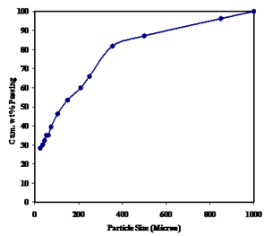 | Figure 1. Size distribution of the iron ore fines |
3.1. Size and Size Wise Density Distribution
Particle-size measurement of the iron ore fines was performed using the standard laboratory sieve shaker and the results are presented in figure 1. From the figure it is revealed that average particle size (i.e d50) the ore fines is 127 microns and 80% of the materials (by weight) have size below 335 microns.Representative sample was taken from each size fraction and measured for specific gravity as per the standard procedure[10]. The specific gravity of each fraction has tabulated in Table 1. From the table it is revealed that the specific gravity of all size fractions are below 4.5 that means the sample contains more of goethite (4.28) than that of hematite (5.2) gains. Further it is also evident from the Table 1 that the specific gravity of the grains are increasing as particle size decreases with the exception that the size fraction below 37 microns particles are less than 4.0 specific gravity which indicates this fraction is rich of ferruginous clayee material i.e. Kaolinite. | Table 1. Specific Gravity of the different size fractions |
| | Size (μm) | Specific Gravity | | +500 | 3.86 | | -500+250 | 4.04 | | -250+150 | 4.25 | | -150+105 | 4.36 | | -105+75 | 4.42 | | -75+53 | 4.46 | | -53+37 | 4.5 | | -37+25 | 3.94 | | -25 | 3.9 |
|
|
3.2. Size Wise Chemical Analysis
The chemical analysis of each size fraction was carried out and the data is tabulated in Table 2. From the table it is evident that +150μm size fractions are iron rich but at -150 μm fractions are relatively rich in alumina and silica. The iron content varies from 59.64% to 64.1% in coarser size fractions i.e> 25 μm. However, a sharp decrease in iron content (52.9%) is observed in below 25 μmwhich indicates that the segregation of alumina and silica in this size fraction is possible. The distribution of iron, alumina and silica at each size fraction is shown in Figure 2. It is evident from the Figure 2 that the iron was distributed at coarser size fractions but silica and alumina is distributed at finer sizes. It is also significant to note that the silica and alumina are evenly distributed up to 200 μmand below this there is an increase in alumina distribution compared to silica.
3.3. XRD Studies
The XRD study was carried out to identify mineral phases present in the sample. The diffractogram is shown in Figure 3. From this figure, it can be seen that the major iron-bearing mineral phases are goethite and hematite and gangue mineral phases are gibbsite, quartz and kaolinite.| Table 2. Size wise chemical analysis |
| | Size (μm) | Wt. (%) | Assay Value (%) | | Fe(T) | SiO2 | Al2O3 | | +850 | 3.7 | 63.50 | 4.35 | 3.60 | | -850+500 | 9.0 | 64.10 | 2.90 | 4.00 | | -500+355 | 5.3 | 63.65 | 3.20 | 4.20 | | -355+250 | 15.7 | 62.79 | 4.00 | 4.75 | | -250+210 | 6.0 | 63.70 | 3.22 | 4.63 | | -210+150 | 6.4 | 63.71 | 3.00 | 4.87 | | -150+105 | 7.1 | 60.48 | 3.36 | 5.13 | | -105+75 | 6.8 | 60.67 | 3.10 | 5.10 | | -75+63 | 4.3 | 60.04 | 3.52 | 5.58 | | -63+53 | 0.1 | 59.64 | 4.62 | 5.15 | | -53+45 | 2.6 | 60.05 | 3.52 | 5.46 | | -45+37 | 2.2 | 61.50 | 3.69 | 5.14 | | -37+25 | 1.8 | 63.21 | 3.92 | 4.84 | | -25 | 28.30 | 52.90 | 7.88 | 8.22 |
|
|
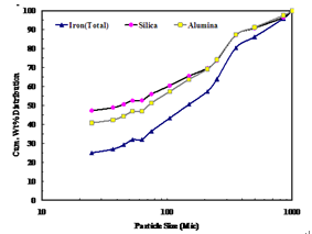 | Figure 2. Iron, alumina and silica distribution at different sizes |
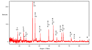 | Figure 3. Diffractogram of the feed sample (H: Hematite, Go: Goethite, G: Gibbsite, K: Kaolinite, Q: Quartz) |
3.4. SEM Studies
The mineralogical studies were conducted using SEM (Scanning Electron Microscopy) with an EDS (Energy Dispersive Spectroscopy) attachment. The study was focused, mainly to identify the elemental composition of the mineral grains present in the sample, throughphotomicrographs and microanalysis. A number of images were processed and it can be seen from the Figure 4(a) that most of the iron-bearing minerals are fully or partially weathered, resulting in substitution of most of the iron oxides with Al in the mineral grains (also observed in the Figure 4(b) of 1). Further it is observed that the point 2 of 4(a) is free of silicate minerals and more porous but alumina rich compared to point 1. This substitution can normally occur in goethite grains which are formed due to the weathering of iron oxide particles (hematite). It was also observed from the figure 4b point 3 that kaolinite and gibbsite are the major gangue phases. 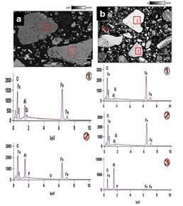 | Figure 4. SEM micrograph along with microanalysis |
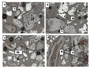 | Figure 5. Microscopic Studies of the head sample (H – Hematite, G – Goethite, Gb – Gibbsite, K - Kaolinite) |
3.5. Microscopic Studies
From the microscopic study, the grains that are observed in the sample are hematite, goethite, gibbsite, quartz, and kaolinite. From the mineralogy it is evident that the sample has two distinct types of valuable minerals i.e., (i) predominantly crystalline hematite grains (fine to medium grained) carrying disseminated inclusions and (ii)micro-crystalline hematite particles intermixed with micro-crystalline goethite and gibbsite. Vitreous goethite particles are abundant in the sample. Goethite replaces hematite in different degrees (Figure 5a and 5b) and fills up the voids and fractures during weathering. Kaolinite occurs in intimate association with goethite but free quartz grains are very rarely observed therefore it is assumed that the silica is available in the form of Kaolinite. Colloform texture of the weathered goethite was observed in the Figure 5(d). Predominant alumina-contributing mineral is gibbsite and occurs intimately intermixed with goethite (Figure 5c) and hematite. More over association of gibbsite with goethite is more than that of hematite. Gibbsite and clay minerals (Kaolinite) grains are present as microcrystalline to cryptocrystalline aggregates and are thoroughly intermixed with goethite, and other silicate minerals. Majority of the kaolinite grains are embedded with iron oxide/ hydroxide minerals as shown in Figure 5d. Several samples were processed for the quantifying the different mineral concentration in the feed sample. The mineral analysis of the feed is tabulated in the Table 3. It is observed that only 11% of the total weight is of liberated hematite grains whereas 23%is of goethite. About 60% of the iron bearing minerals is locked with different proportions of gangue minerals.| Table 3. Mineral analysis of the feed sample |
| | Minerals | Weight (%) | | Hematite | 11 | | Goethite | 23 | | Interlocked (Hematite + Goethite) | 21 | | Kaolinite | 3 | | Gibbsite | 2 | | Interlocked(Hematite+Goethite+Al bearing minerals) | 12 | | Interlocked (Goethite+Kaolinite) | 13 | | Interlocked (Goethite+Gibbsite) | 8 | | Quartz | 1 |
|
|
4. Beneficiation Studies
It is evident from the detailed characterization of the iron ore fines that most of the alumina and silica are concentrated at finer sizes. Based on sound understanding of the characterisation, two conceptual flow sheets are considered and shown in the figure 6 and 7. In both flow sheets, the upstream operation involves classification by floatex density separator for the effective desliming the feed. The underflow of the floatex density separator is treated in two ways. The first flow sheet was designed in order to utilize the differences in size, specific gravity and the second one size, specific gravity, and magneticsusceptibility between the different minerals. The first flow sheet utilises two stage gravity separations by using spiral concentrator and shaking table. The second one utilises single stage gravity concentration by spiral concentrator followed by single stage magnetic operation by wet high intensity magnetic separator (WHIMS) to attain the better recovery for the sinter / pellet grade concentrate. 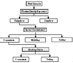 | Figure 6. The flow diagram for the option 1 |
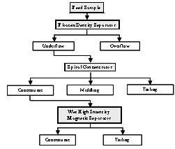 | Figure 7. The process flow diagram for the option 2 |
| Table 4. Results of the Floatex Density Separator test (TW: Teeter Water Flow Rate, SP: Set Point) |
| | Test No. | Prod. | Wt% | Assay% | Fe Dist% | Conditions | | Fe% | SiO2 | Al2O3 | | 1 | U/F | 76.8 | 63.7 | 2.9 | 4.6 | 81.9 | TW: 8 lpmS P: 34 | | O/F | 23.2 | 46.2 | 10.5 | 10.1 | 17.9 | | 2 | U/F | 64.2 | 64.2 | 2.2 | 3.9 | 68.9 | TW: 8 lpmS P: 40 | | O/F | 35.8 | 51.6 | 8.5 | 9.6 | 30.9 | | Head Feed | 59.7 | 4.7 | 5.9 | |
|
|
4.1. Classification Studies by Floatex Density Separator (FDS)
The Floatex Density Separator (FDS) was used for separating the ferruginous clayee material from the iron ore fines. The FDS iscounter-current, autogenous teetered bed separator. Particles are segregated based on the principle of hindered settling and fluidization. The experiments were undertaken in a FDS (Model No. LPF-0230, supplied by Outokumpu) of 230 × 230 mm cross-section and 530 mm height of square tank with 200 mm conical section elevation. The feed distributor is located at 230mm from the top. Series of tests were conducted by varying set point and teeter water flow rate whereas the other variables such as feed rate (0.3 tph of dry solids) and feed pulp density (30% solids by weight) were kept constant. After each test, both the underflow and overflow fractions were collected and analyzed for quality. Few tests were targeted for higher yield (more than 70%) whereas the other few tests aim for better quality. The chemical analysis of the optimized test products are tabulated in Table 4.It is evident that as the set point increases i.e. teeter bed density as well as the bed height increases, the percentage recovery of Fe to underflow is decreased from 81.95% to 68.99%. Simultaneously the Al2O3 and SiO2 distribution in overflow is increased from39.26% and 51.97% to 57.7% and 65.36% respectively. The under flow fraction of FDS contains about 64%±0.5% Fe content which could not be improved further due to its wide size range. Thus obtained underflow fraction was treated further for improving the quality by increasing the Fe content or by decreasing Al2O3 content. The underflow product of test 1 and 2 are used for the flow sheet 1 and 2 respectively.
4.2. Option 1: Flow sheet comprising of Hindered Settling Classification Followed By TwoStage Gravity Concentrations
| Table 5. Results of the spiral concentrator test (Conditions: Feed Rate-0.21 tph of dry solids, splitter position-17cm from the centre) |
| | Product | Wt% | Assay (%) | Fe (%)Dist. w.r.t. Head | | Fe (T) | SiO2 | Al2O3 | | Con. | 53.4 | 64.3 | 2.4 | 3.88 | 44.13 | | Midd. | 38.0 | 63.8 | 2.8 | 3.91 | 31.18 | | Tail. | 8.6 | 60.1 | 6.2 | 12.35 | 6.64 | | Feed | 63.7 | 2.9 | 4.62 | |
|
|
The flow scheme for the option 1 is given in Figure 6. The underflow fraction of FDS Test 1 contains 63.78% Fe content but the alumina content is 4.6% which is detrimental for iron making process. The high capacity gravity concentrating device (spiral concentrator) was used to remove the alumina content. The spiral concentrator (model no. LC 3000, Carpco Inc, USA make) used for the test work is having pitch of 16inches and 5 turns. Number of tests was conducted by varying the feed rate and splitter position by keeping the feed pulp density (15% solids by weight) constant. The best test results are tabulated in Table 5. It may be witnessed from this Table 5 that the iron value improved marginally to 64.32% with a substantial reduction of alumina and silica values to 3.88% and 2.48% respectively, with 44.13% Fe distribution with respect to the original feed.
4.3. Enrichment of Spiral concentrate Product using Shaking Table
Since the concentrate product of the spiral concentrator contains 3.88% Al rendering it unsuitable for the iron making process, this fraction was subjected to wet gravity concentrating table to further improve the quality.The wet gravity concentrating table Model No. 15 S (Deister Concentrator Company Inc., USA) was used for the test work. Tests were conducted by varying the process variables like wash water flow rate and deck inclination by keeping the other variables such as shake amplitude (10cm), shake frequency (150 cycles/min) constant and best test results along with the test conditions are tabulated in Table 6. It may be noticed from the results that the iron value could be improved to 66.82% with consequential lowering of alumina and silica values to 2.1% and 1.55%, respectively. However, the quality of the product with respect to the alumina is not achieved for sinter/pellet making. From the study it is envisaged that classification followed by two stage gravity concentration would not be able to produce the required product quality (less than 2% alumina). So an alternative option has to be formulated to treat the iron ore fines for obtaining the required quality of the concentrate product.
4.4. Option 2: Flow Sheet Comprising of Hindered Settling Classification Follow by Single Stage Gravity and Magnetic Separation
The detailed flow scheme for the option 2 is given in Figure 7. In order to improve the quality of concentrate a second option (Flow sheet 2), involving classification followed by single stage gravity operation and thus obtained concentrate was cleaned with magnetic operation. The FDS underflow fraction of test 2 contains 64.25% Fe content but the alumina content is detrimental impurity for iron making process hence, this fraction was subjected to spiral concentrator to separate the alumina bearing particles. Number of tests was conducted by varying the feed rate, splitter position and the best test conditions with results are tabulated in Table 7. It may be observed from this Table 7, that the iron value improvedmarginally to 65.86% with a substantialreductionof alumina and silica values to 3.09% and 2.15% respectively, with 41% Fe distribution with respect to the original feed.
4.5. Enrichment of Spiral Concentrate Product Using WHIMS
The concentrate fraction of the spiral concentrator was subjected to wet high intensity magnetic separator (WHIMS) in order to improve the quality of the concentrate by differentiating the magnetic susceptibility of the particles. Laboratory model of high intensity wet magnetic separator supplied by Box-mag Rapid ltd, England was used for the test work. Series of tests were conducted by varying the magnetic intensity whereas the other variables such as feed rate 0.08 tph of dry solids, pulp density 20% solids by weight, wash water flow rate 5lpm were maintained constant and the best test conditions with results are tabulated in Table 8. It may be noticed from the WHIMS results that the iron value could be improved to 67.77% with consequential lowering of alumina and silica values to 1.67% and 1.53%, respectively. The overall yield is 25.35% and the overall recovery of the total iron is 28.95% with respect to the original feed.From the above study it is observed that the concentrate produced from option 1 was assaying 66.82% Fe, 1.55% SiO2 and 2.10% Al2O3. It is calculated that about 92.6 and 92.11% of silica and alumina rejected in this process flow sheet 1 respectively. Similarly the concentrate produced from the flow sheet 2 was suitable for the pellet/sinter making (67.77% Fe, 1.67% SiO2 and 1.53% Al2O3. The rejection value of silica and alumina in the flow sheet 2 are 90.96% and 93.47% respectively.| Table 6. Results of the wet gravity concentrating table test (Conditions: Wash water flow rate- 4 lpm, Deck tilt angle- 3 degree) |
| | Product | Wt% | Assay (%) | Fe (%)Dist. w.r.t. Head | | Fe (T) | SiO2 | Al2O3 | | Concentrate | 54.8 | 66.8 | 1.5 | 2.1 | 25.1 | | Middling | 19.5 | 63.2 | 3.2 | 4.5 | 8.4 | | Tailing | 25.7 | 57.0 | 5.2 | 11.9 | 10.1 | | Feed | 64.3 | 2.4 | 3.8 | |
|
|
| Table 7. Results of the spiral concentrator test (Conditions: Feed rate- 0.25tph and splitter position- 15 cm) |
| | Products | Wt% | Assay% | Fe Dist% w.r.t. Feed | | Fe% | SiO2 | Al2O3 | | Concentrate | 58.5 | 65.86 | 2.15 | 3.09 | 41.38 | | Middling | 25.0 | 63.58 | 2.60 | 4.10 | 17.07 | | Tailing | 16.5 | 59.56 | 5.63 | 8.51 | 10.56 | | Head Feed | 64.25 | 2.62 | 3.94 | |
|
|
| Table 8.Results of the wet high intensity magnetic separator (WHIMS) tests |
| | Products | Wt (%) | Assay% | Fe Dist% w.r.t. Feed | | Fe | SiO2 | Al2O3 | | Mag. | 67.9 | 67.7 | 1.67 | 1.53 | 28.95 | | Mid. | 18.0 | 65.2 | 1.76 | 3.78 | 7.39 | | Non-Mag. | 14.1 | 58.9 | 5.59 | 8.05 | 5.23 | | Head Feed | 65.8 | 2.15 | 3.09 | |
|
|
| Table 9. Mineralogical analysis of the concentrateproducts of two studied flow sheet |
| | Minerals | Weight (%) | | Option 1 | Option 2 | | Hematite | 37 | 47 | | Goethite | 5 | 4 | | Interlocked (Hematite + Goethite) | 39 | 42 | | Interlocked (Hematite + Goethite + Al bearing minerals) | 7 | 5 | | Interlocked (Goethite + Kaolinite) | 8 | 2 | | Interlocked (Goethite + Gibbsite) | 4 | - |
|
|
The mineral analysis of the concentrate products from both the flow sheets were analysed and given in Table 9 which indicates that the goethite content is decreased (free/ interlocked) in the flow sheet 2 compared to flow sheet 1. It is also noted that as the goethite content decreases the alumina content in the products also decreases as the alumina bearing minerals are intimately associated with the goethite grains.The mineral analysis of the concentrate products from both the flow sheets were analysed and given in Table 9 which indicates that the goethite content is decreased (free/ interlocked) in the flow sheet 2 compared to flow sheet 1. It is also noted that as the goethite content decreases the alumina content in the products also decreases as the alumina bearing minerals are intimately associated with the goethite grains.
5. Summary and Conclusions
The present work explains about exploring the possibility of beneficiating the high alumina bearing iron ore fines of India. Detailed particle characterization and subsequent beneficiation studies of the high alumina iron ore fines revealed the following distinctive points that are helpful for developing the process flow sheet strategy. a. The XRD study revealed that goethite and hematite are the main iron-bearing phases. Gibbsite, kaolinite, and quartz are the main gangue phases. b. The size wise chemical analysis illustrates that the major impurities are silica and alumina are concentrated at finer size fraction, which contains ferruginous clayee material such kaolinite etc.c. Microscopic study revealed that the iron bearing grains (hematite and goethite) are highly weathered due to the surface weathering of the bulk ore in the deposit. During sizing and washing this weathered portion being accumulated as fines. It is also evident that the hematite is altered to partially/fully to goethite. Further the kaolinite occurs in intimate association with ochreous goethite. The gibbsite is dominant at finer fraction by coating on the iron bearing minerals.d. The separation of very fine ferruginous clayee material from the iron fines becomes more efficient with the use of Floatex Density Separator. Thus, the number of unit operations employed in the circuit would be condensed and hence treating this ore fines becomes more compact and simpler. e. From the above two beneficiation schemes were formulated by using the gravity concentration and magnetic separation. The final concentrate of flow sheet 1 assayed 66.82% Fe, 1.55% of SiO2 and 2.10% of Al2O3 with an overall recovery of iron is 25.15%. The final concentrate of flow sheet 2 assayed 67.77% of total iron, 1.67% of silica and 1.53% of alumina with an overall recovery of 28.95% Fe.f. The rejection values for both the gangue contents (silica and alumina) in these two flow sheets are higher than 90%. The mineral analysis of the concentrate products of both the flow sheets concludes that as the goethite content (free/interlocked) increases, the alumina content also increases simultaneously.
ACKNOWLEDGEMENTS
The authors are thankful to Tata Steel Ltd., management for all support, encouragement and permission to publish this work.
References
| [1] | M P Srivastava, S K Pan, N Prasad,, and B K Mishra, “Characterization and processing of iron ore fines of Kiriburu deposit of India”, International Journal of Mineral Processing, vol. 61, no.2, pp. 93–107, 2001. |
| [2] | P Bhattacharya, S R Ghosh, J P Srivastav, P K Sinha, S K Sengupta, S C Maulik, “Beneficiation studies of Bolani iron ore”, in Proceedings of National Seminar on Processing of Fines, NML Jamshedpur, India, pp. 156–162, 1997. |
| [3] | S Mahiuddin, S Bandopadhyay and J N Baruah, ‘‘A study on the beneficiation of Indian iron ore fines and slime using chemical additives”, International Journal of Mineral Processing, vol. 11, pp. 285-302, 1989. |
| [4] | K Hanumantha Rao and K S Narasimhan, ‘‘Selective flocculation applied to Barsuan iron ore tailings’,’ International Journal of Mineral Processing, vol. 14, pp. 67–75, 1985. |
| [5] | B Gujraj, J P Sharma, A Baldawa, S Arora, N Prasad and A K Biswas, ‘‘Dispersion–flocculation studies on hematite-clay systems’,’ International Journal of Mineral Processing, vol. 11, pp. 285-302, 1983. |
| [6] | B Das, S Prakash, B K Mohapatra, S K Bhaumik, K S Narasimhan, “Beneficiation of iron ore slimes using hydrocyclone”, Mineral and Metallurgical Processing, vol. 9, no. 2,pp. 101–103, 1995. |
| [7] | S Mohanty and B Das, “Optimization Studies of Hydrocyclone for Beneficiation of Iron Ore Slimes”, Mineral Processing and Extractive Metallurgy Review, vol. 31, no. 2, pp. 86- 96, 2010. |
| [8] | B Das,B. K Mohapatra, P. S. R Reddy, and S Das, ‘‘Characterisation and beneficiation of iron ore slimes for further processing’’, Powder Handling and Processing, vol. 7, no. 1, pp. 41–44, 1995. |
| [9] | B Sarkar, A Das,S Roy, S.K Rai, "In depth analysis of alumina removal from iron ore finesusing teeter bed gravity separator", Mineral Processing and Extractive Metallurgy (TIMMC), Vol. 117, no. 1, 2008. |
| [10] | B A Will, T Napier Munn, Mineral Processing Technology: An Introduction to the Practical Aspects of Ore Treatment and Mineral, Elsevier Science & Technology Books, 7th Edition, 2006. |
 Abstract
 Reference
 Full-Text PDF
 Full-Text HTML