-
Paper Information
- Paper Submission
-
Journal Information
- About This Journal
- Editorial Board
- Current Issue
- Archive
- Author Guidelines
- Contact Us
International Journal of Mechanics and Applications
p-ISSN: 2165-9281 e-ISSN: 2165-9303
2021; 10(1): 20-25
doi:10.5923/j.mechanics.20211001.03
Received: May 21, 2021; Accepted: May 31, 2021; Published: Jun. 15, 2021

Residual Stress Determination Experiment from Pile-up Morphology on Spherical Indentation
 Abstract
 Reference
 Full-Text PDF
 Full-text HTML
Jianhao Feng, Jingyi Shao
Faculty of Civil Engineering and Mechanics, Jiangsu University, Zhenjiang, China
Correspondence to: Jianhao Feng, Faculty of Civil Engineering and Mechanics, Jiangsu University, Zhenjiang, China.
| Email: |  |
Copyright © 2021 The Author(s). Published by Scientific & Academic Publishing.
This work is licensed under the Creative Commons Attribution International License (CC BY).
http://creativecommons.org/licenses/by/4.0/

Alloys play a vital role in aircraft, high-speed rail, ships and other large equipment. However, residual stress will be introduced into metal materials in the process of manufacture, processing, and surface treatment in different degrees. These introduced residual stresses not only has an important influence on the performance of material services, such as the crack strength, fatigue resistance, corrosion resistance, but also affecting the dimensional stability of material components and the safety of the structure. Thus, it is of great significance to measure the residual stress of engineering materials accurately. In this paper, the experimental test platform was initially to generate the pile-up morphology. Then, the relationship between residual stress and pile-up morphology was studied by experimental investigation. Finally, the experimental results verify the accuracy of the method based on spherical indentation of the pile-up morphology.
Keywords: Residual stress, Instrumented indentation testing, Spherical indentation, Pile-up morphology
Cite this paper: Jianhao Feng, Jingyi Shao, Residual Stress Determination Experiment from Pile-up Morphology on Spherical Indentation, International Journal of Mechanics and Applications, Vol. 10 No. 1, 2021, pp. 20-25. doi: 10.5923/j.mechanics.20211001.03.
1. Introduction
- The safety and reliability of large infrastructure such as aircraft, high-speed trains and ships have always been the focus of social concern. In these large facility projects, alloys often play an important role as key components. For example, in the aero-engine, superalloy materials are usually used in the combustion chamber, turbine disc, turbine blade and other core components, accounting for about 40%~60% of the total material of the engine. However, residual stress is inevitably introduced in the process of mechanical manufacturing, machining and surface treatment of components [1,2]. In the actual service environment, the introduced residual stress will evolve further. The existence and evolution of residual stress directly affect the properties of materials or components, and then threaten the safety of life and property [3,4]. Therefore, it is of great significance to accurately measure the residual stress of engineering materials.The traditional residual stress measurement methods can be roughly divided into mechanical stress relaxation method and physical parameter analysis method. Among them, the mechanical stress relaxation method is generally used to release part of the residual stress in the material, measure the deformation caused by the change of the residual stress, and then calculate the residual stress [5-8]. The mechanical stress relaxation method includes drilling, slitting and cutting of ring core. However, these methods are disruptive and limit the wide use of these techniques in industry. Physical parameter analysis methods, including X-ray diffraction, neutron diffraction, ultrasonic and magnetic Barkhausen noise, can be used to measure the residual stress through the essential properties of materials and nondestructive measurement, and some methods have been partially applied in the industrial field [9-11]. However, these physical methods are limited by the inherent microstructure of the material, and it is necessary to prepare stress-free samples for reference. In addition, X-ray diffraction and neutron diffraction methods cannot be applied directly to amorphous materials because they do not have long-range ordered atomic structures.The instrumented indentation method (IIT) is another promising technique for measuring surface residual stress, which has high displacement and load resolution, and can continuously record the changes of load and displacement during indentation contact. Due to its small indentation range, the components under real service conditions can be detected with non-destructive in real-time. Great efforts have been made to investigate the influence of residual stress on the measurement of mechanical properties using instrumented indentation. In 1996, the influence of the surface residual stress on the results obtained using indentation testing was first investigated by Boshakov and Oliver et al [12,13]. Through experimental observations and finite element analysis, they found that the existence of residual stress had an effect on the contact area at the same depth of indentation, but had a minimum effect on hardness. In order to further study the effects of residual stress on the contact area, Suresh and Giannakopoulos proposed a theoretical model for the determination of the surface residual stresses based on a sharp indentation in 1998 [14]. In 2001, Carlsson and Larsson suggested a correlation between the equi-biaxial residual stress and the size of the contact area [15,16]. Subsequently, Lee et al. investigated the load difference between stressed and unstressed specimens at the same indentation depth to estimate residual stress [17,18]. In 2006, Xu et al. systematically studied the influence of residual stress on the elastic recovery of nano-indentation through a large number of finite element simulations and found that the residual stress not only affected the real contact area but also affected the elastic recovery ratio. Similarly, Carlsson and Lee agree that the contact area ratio in the determination of residual stress was useful. However, it is difficult to measure the contact area directly during indentation tests. To solve this problem, Zhao et al. proposed a method to determine the residual stress of materials based on the load-displacement curves recorded during the indentation process. This method does not need to measure the contact area, but its limitation is that it is only suitable for ideal elastoplastic materials, and a large number of empirical coefficients need to be obtained. All the methods mentioned above are based on the theoretical model of Oliver–Pharr method to obtain material parameters [19].Apart from sharp indenter, a blunt spherical indentation for measuring the residual stress can be used. Taljat and Pharr suggested that spherical indentation is more sensitive to stress effects than sharp indentation through theoretical predictions and finite element analyses [20]. They found that residual stresses have a significant effect on the indentation load-displacement curves in the elastic-plastic transition regime. Subsequently, Swander et al. proposed two methods of determining equi-biaxial residual stresses via spherical indentation based on the discovery of Taljat and Pharr [21]. However, the limitation of spherical indentation is that the yield strength of the material needs to be known in advance and the actual contact area needs to be measured. To solve this weakness, Peng et al. proposed a method to estimate the equi-biaxial residual stress and elastic-plastic parameters of metals simultaneously via instrumented spherical indentation which can avoid preknowledge of the yield strength and measuring the contact area [22].Recently, through theoretical analysis and finite element simulation, Liu and Shen et al. found that the pile-up morphology around the indentation after unloading can be associated with the direction of surface residual stress and the amount of pile-up is dependent on the magnitude of surface residual stress [23,24]. The greatest advantage of this method is that the pile-up height generated in the experiment can be easily measured. Additionally, some researchers have extended the indentation method to nonmetallic materials. The effect of the internal microstructure especially the pores on mechanical properties of plasma-sprayed coatings using sharp indentation was investigated by Qiao et al [25]. Akahori et al. proposed a method for evaluating the residual stress of polymeric materials using spherical indentation tests.In general, the Oliver-Pharr method is the most widely used method for measuring material parameters and residual stress in current research [19]. However, when using the Oliver-Pharr method, the main problem is how to calculate the actual contact area. At present, there have been some studies on how to calculate the contact area or the influence of avoiding the contact area [22,26]. In addition, spherical indentation is more sensitive to stress effect than sharp indentation, but the specific value of the difference needs to be further studied. Some researchers pointed out that when calculating the residual stress of soft materials, the error margin of the results obtained by the Suresh model and Lee model would be relatively large, which might not be applicable to the calculation [27]. In addition, it seems more intuitive to characterize the residual stress through the packing morphology. However, previous studies on the packing morphology are mostly based on finite element analysis and lack of experimental verification. Therefore, it is necessary to judge whether the method based on the packing morphology is accurate.In this paper, the experimental test platform were established to generate the pile-up morphology first. Then, the relationship between residual stress and pile-up morphology was studied by experimental investigation. Finally, the experimental results verify the accuracy of the method based on spherical indentation of the pile-up morphology.
2. Experimental Procedure
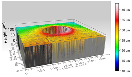
- This study used a Brinell hardness tester as an indentation equipment (HBE-3000M) to investigate the relationship between pile-up morphology and residual stress. A spherical indenter was used, as shown in Fig. 1 (a). The indentation equipment has 12 loading load presets in the loading range 62.5-3000 kgf, equipped with a rigid spherical indenter with a diameter of 1 mm, 2.5mm, 5mm, and 10mm, respectively. The indenter of 2.5 mm diameter was selected for this experiment. As shown in Fig. 1 (b), the white light interferometer (Filmetricsinc, Profilm3D) was used to obtain the pile-up morphology after indentation unloading and to extract its maximum pile-up height. The equipment test accuracy is 0.01μm, which meets the accuracy requirements for this experiment.
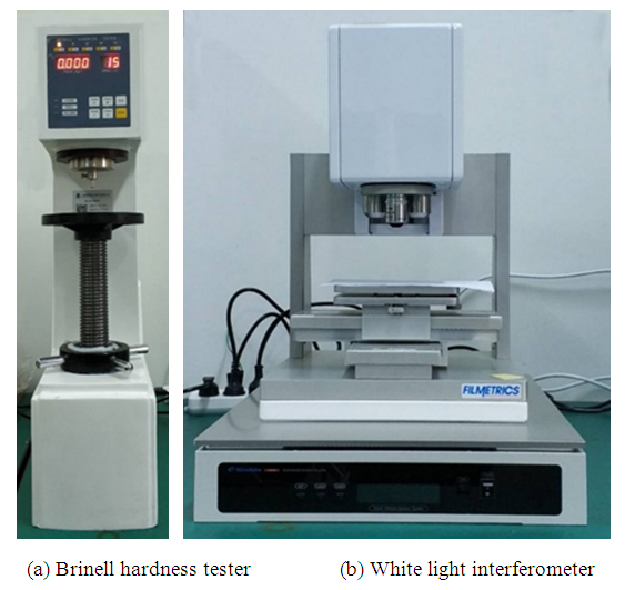 | Figure 1. Experimental setup |
 | (1) |
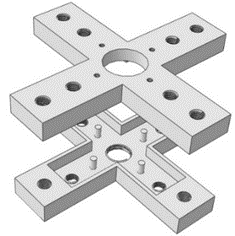 | Figure 2. 3D schematic diagram of residual stress application fixture |
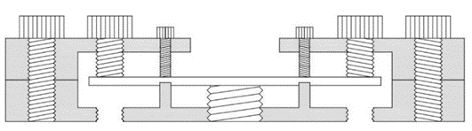 | Figure 3. Schematic diagram of stress application fixture |
3. Results and Discussions
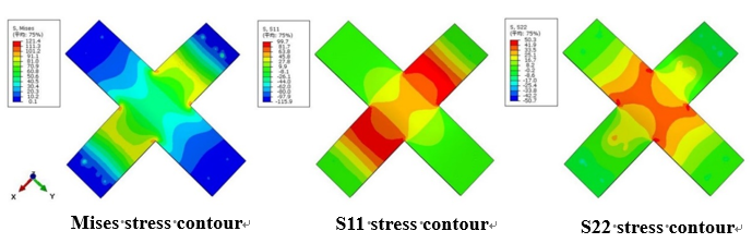
- Finite element simulation (ABAQUS 6.14) was used to simulate and analyze the loading condition of the specimen in the experiment to ensure that the stress applied on the material surface by the loading device is in the expected stress state, in which the simulation results of the equi-biaxial stress state are shown in Fig. 4. The S11 and S22 stress contours generated on the surface of the specimen are the same after simulating the application of 100 MPa of equi-biaxial stress, which indicates that uniform equi-biaxial stress was generated inside the specimen. Fig. 5 shows the stress contour of the simulated specimen after applying 100 MPa and 50 MPa stress respectively. In the figure, the amount of S11 and S22 stress contour on the surface of the specimen are twice different, indicating that the non-equi-biaxial stress as expected was generated inside the specimen.
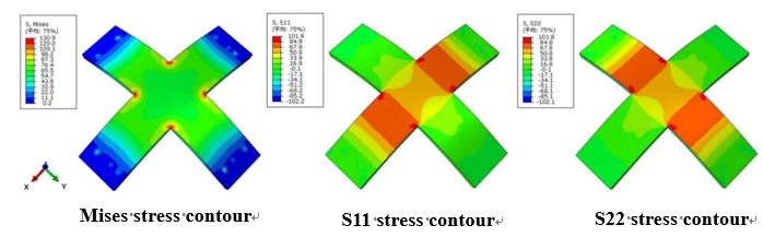 | Figure 4. Stress contour of equi-biaxial stress |
 | Figure 5. Stress contour of non-equi-biaxial stress |
 | Figure 6. Morphology near the indentation (σx =-75MPa and σy=75MPa) |
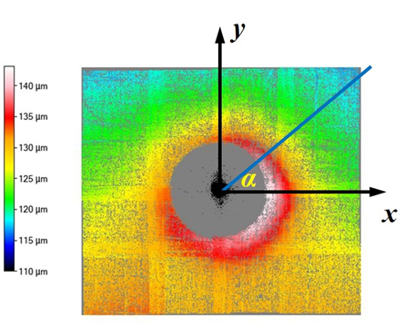 | Figure 7. The schematic diagram of the established polar coordinate system |
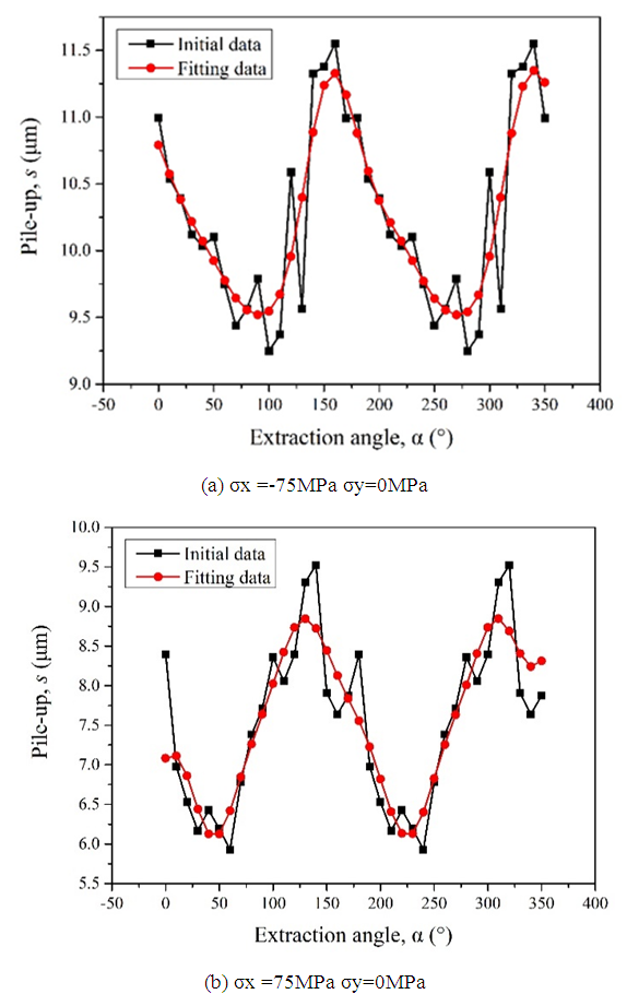
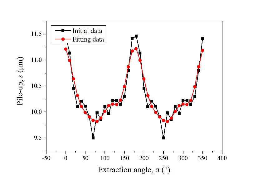 | Figure 8. Distribution diagram of maximum pile-up height (σx =-75MPa σy=75MPa) |
 | Figure 9. Distribution diagram of maximum pile-up height |
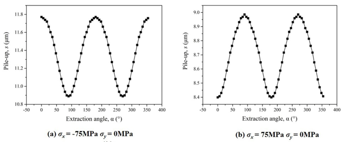 | Figure 10. Finite element simulation results of maximum pile-up height |
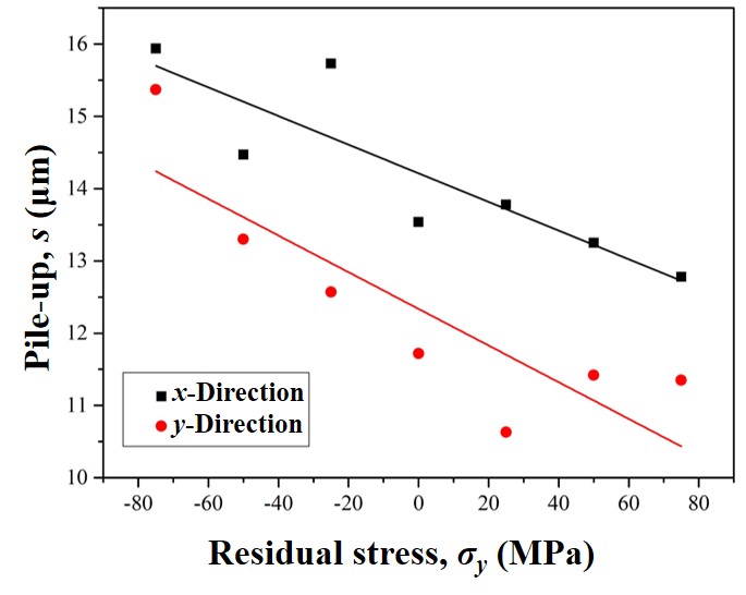 | Figure 11. Schematic diagram of a variation of maximum pile-up height with residual stress |
4. Conclusions
- In this paper, based on the method proposed by Shen et al., the method of measuring the residual stress by the indentation method is systematically and deeply studied with experiment. The experimental results show that the change curve of the stacking height presents a sinusoidal trend, and the direction corresponding to the peak and valley points of the curve is the main direction of stress application. Therefore, the direction of stress can be directly determined by the peak and valley points in the distribution map of the maximum packing height near the indentation point. Besides, as the stress in the y-direction changes from the compressive stress state to the tensile stress state, both the maximum pile-up height in the x-direction and y-direction show a trend of gradual decrease. Also, it can be found that the reduction velocity of pile-up height in the x-direction is smaller than that in the y-direction, because the y-direction is the main direction of stress change, so it is more sensitive to stress change.