-
Paper Information
- Paper Submission
-
Journal Information
- About This Journal
- Editorial Board
- Current Issue
- Archive
- Author Guidelines
- Contact Us
International Journal of Mechanics and Applications
p-ISSN: 2165-9281 e-ISSN: 2165-9303
2021; 10(1): 11-19
doi:10.5923/j.mechanics.20211001.02
Received: Mar. 18, 2021; Accepted: Mar. 29, 2021; Published: Apr. 2, 2021

Employing a Low-Cost Desktop 3D Printer: Challenges, and How to Overcome Them by Tuning Key Process Parameters
 Abstract
 Reference
 Full-Text PDF
 Full-text HTML
Kantaros Antreas, Dimitrios Piromalis
Department of Industrial and Product Design Engineering, University of West Attica, Greece
Correspondence to: Kantaros Antreas, Department of Industrial and Product Design Engineering, University of West Attica, Greece.
| Email: |  |
Copyright © 2021 The Author(s). Published by Scientific & Academic Publishing.
This work is licensed under the Creative Commons Attribution International License (CC BY).
http://creativecommons.org/licenses/by/4.0/

3D printing has been referred as being the third industrial revolution and was introduced as an innovative fabrication method in order to overcome shortcomings of existing prototyping fabrication techniques. This method involved the forthright fabrication of three-dimensional solid objects derived from a digital CAD file. The advancements in additive manufacturing technology in combination with the expiration of several patents led to the dramatic reduction of 3D printing equipment purchasing and usage costs thus making the technology available to wide masses. However, due to the modus operandi of the additive process, that functions in a layer to layer building principle, technical expertise is needed to properly operate such devices. Therefore, several parameters have to be carefully tuned and a certain level of expertise is required in order to accomplish the desired printing results. In addition, the newly introduced FFF lower-end desktop 3D printers suffer more from these disadvantages and therefore limit users to intermediate or unsatisfactory printing results. This article looks into 3D printing challenges while stressing the contribution of key process parameters in printing results. Different process parameter settings are tested, depicting the differences in printing quality, while optimal parameter settings are being proposed.
Keywords: 3D printing, Desktop 3D printer, Process parameter setting, 3D printing quality, 3D printing challenges, FFF 3D printer
Cite this paper: Kantaros Antreas, Dimitrios Piromalis, Employing a Low-Cost Desktop 3D Printer: Challenges, and How to Overcome Them by Tuning Key Process Parameters, International Journal of Mechanics and Applications, Vol. 10 No. 1, 2021, pp. 11-19. doi: 10.5923/j.mechanics.20211001.02.
Article Outline
1. Introduction
- Twenty first century markets demand the constant evolution of presently existing products. Multinational companies alongside with innovative small and medium-sized enterprises (SMEs), try to offer constantly optimized merchandise according to the continuously altering consumer needs. In addition, local maker communities try to find cheap and accessible methods that will allow them to fabricate items and functional parts for their individual projects. Thus, the needs for minimizing product development time and the introduction of affordable and attainable fabrication methods stand stronger than ever. The importance of prototyping, especially in the development of high novelty products has been extensively reported in the literature [1,2]. However, pre-existing prototype manufacturing methods are extremely time consuming and resulting prototypes serve mostly visual purposes and cannot serve as functional prototypes. Furthermore, hobbyists and DIY makers often have to deal with expensive tooling and complicated manufacturing techniques that cannot be afforded or they require a degree of expertise [3] that cannot be acquired easily.In the direction of overcoming such limitations, an innovative manufacturing method was introduced. This method involved the forthright fabrication of three-dimensional solid objects derived from a digital CAD file. This was made possible by employing additive manufacturing techniques. There, the consecutive deposition of melted material layers leads to the final creation of an actual physical object. This technology is also known under the term “3D Printing” and offers the potential to swiftly transform an existing CAD design to a real-world physical object. This is made possible without the presence of expensive molds and industrial tooling infrastructure. It was invented in 1986 by Charles Hull who coined the term “Stereo Lithography”, which was the name of this first 3D printing technique. In 1992 the first commercially available 3D Printer was introduced by the company “3D Systems”. Technological breakthroughs in the field of desktop computers and the rising availability of industrial lasers led to the introduction of many new 3D printing processes in the late 1980s and 1990s. These, considered techniques like selective laser sintering and fused deposition modelling. At a first glance, 3D printing methods offer designers the potential to come up with 3D designs and fabricate them in a timely and inexpensive manner. Thus, a design can be reevaluated and modified leading to the desired item. In this way, hobbyists and DIY makers are now given the necessary tool that can turn their designs into physical parts, cheaply and fast [4]. 3D printing techniques are also described as “the new industrial revolution” [5,6]. However, 3D printing did not come without shortcomings. The most important drawbacks were the high acquisition and usage costs along with the amount of technical expertise needed to properly operate such devices. Especially aircraft and automotive enterprises, who were the pioneers of 3D printing to perform prototyping operations, blamed the high cost of using this technology for having kept the practice from going mainstream until the late 2000s [7]. Nowadays, thirty years after the first 3D printer introduction, most of these limitations have been overcome. The main reasons for this evolution are the introduction of contemporary and enhanced 3D printing technologies, new materials, government funding, perpetually expanding application fields accompanied by raised user awareness of the 3D printing advantages upon conventional manufacturing methods like injection molding and CNC [8]. Moreover, the expiration of several patents in 3D printing over the current and following years is expected to give further boost in the growth of 3D printing market. The impact of this technology continues to grow due to its even deeper penetration in various fields and also in means of a continuously growing number of people using it worldwide in the direction of self-employing a 3D printer in almost every household of the developed world in the next decade [9,10].With this in mind, the introduction of low-cost desktop 3D printers in the current decade is immense. Buyers can choose from a vast range of such printers ranging from 300$ - 1000$. In most cases, these printers have turned into full commercial products as they are being sold in big department stores, come fully assembled, are well packaged and accompanied with manuals and starters’ kits. They mostly employ FDM technology and give users the ability to use various materials like PLA and ABS in different colors and sometimes by using more than one extruder.Albeit the fact that the launch of such a 3D printers’ range brings this technology closest to the masses, the utilization of these printers by users does not come without a number of important challenges. In many cases, low cost 3D printers do not come preassembled and are sold in the form of DIY kits that users cannot easily assemble without prior mechanical competence and knowledge. Printing quality results is another big issue, as in many cases they are intermediate or poor leading to the rejection of the printed part. The selection of the proper material for different printing projects is another matter of contention for the users, since different materials have different properties and are not always suitable. Calibration of the printer’s extruder head is also another arduous matter for the users since in most cases it is conducted manually and it is a rather demanding and time-consuming process with doubtful results.Despite the aforementioned challenges, the biggest challenge faced by low cost desktop 3D printer users is the proper setting of several process parameters, prior to printing, that have immense impact on the overall quality and mechanical behavior of the 3D printed part. These process parameters have to do with layer thickness, extruding temperature, printing speed, retraction distance etc. Unfortunately, the correct setting of these parameters is a rather difficult task for the end-user because the significance of every parameter and their interaction cannot be easily evaluated. Correspondingly, failed prints cause frustration and raise skepticism about 3D printing on user communities. Failed prints may occur for a number of reasons. Motor stall, nozzle blockage, bearing failure, timing belt break, abnormal extrusion and 3D Printed item detaching from the platform are some of the reasons reported for failed 3D Prints [11]. Failed prints are estimated to cause a material waste of around 19% according to the literature [12]. The total percentage of the material wasted in FDM 3D Printing processes is estimated to be 34%, adding the material used for the support structures as well [12].
2. Challenges and Process Parameters
- The additive manufacturing process principles that the majority of low-cost desktop 3D printers work under, are derived from the Fused Deposition Modelling (FDM) technology and this technique is now known under the term Fused Filament Fabrication (FFF) [13]. FFF is a layered manufacturing technology that fabricates parts of complex geometry by the layering of extruded materials such as Acrylonitrile–Butadiene–Styrene (ABS), Poly-Lactic-Acid (PLA) and Polyethylene-Terephthalate- Glycol (PETG) thermoplastics. The material is initially in the form of a flexible filament which is then melted and extruded through a heated nozzle in a prescribed road pattern onto a continuously moving platform bed in a layer by layer basis [14]. The basic components of a desktop FFF 3D Printer are depicted in figure 1.
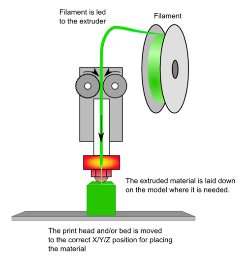 | Figure 1. Basic components of a desktop FFF 3D Printer |
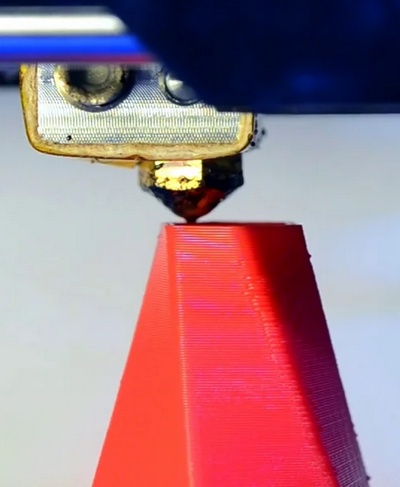 | Figure 2. Material deposition in FFF 3D printing technique |
 | Figure 3. Warping of 3D printed part due to stress build-up |
 | Figure 4. Inaccurate attribution of the initial design due to staircase effect |
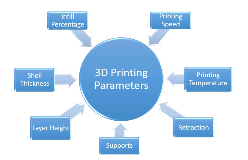 | Figure 5. 3D printing process parameters with immense contribution in the printing results |
3. Results of Process Parameter Setting
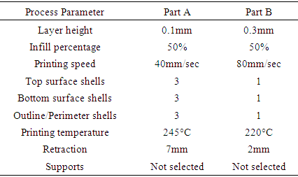
- In order to make a brief demonstration of the aforementioned process parameter setting contribution to a 3D printed part, a part was designed and fabricated in an FFF 3D printer. For this reason, the part was printed twice with different process parameter settings in order to depict possible variations in printing quality. The first part (hereafter referred as part A) was fabricated selecting the proper settings while the second part ((hereafter referred as part B) was fabricated with deliberately selecting inappropriate settings, like an inexperienced user would possibly do.The part chosen, is a gear component derived from a larger mechanical assembly. It was designed using Dassault SolidworksTM 3D CAD Software. The file was exported in stl format and forwarded to the 3D Printer’s “XYZ Ware for Pro” dedicated slicing software. The 3D printer used for the printings was a Da Vinci 1.0 Pro 3in1 printed manufactured from XYZprinting, Inc. with a purchase cost under 1000$ and the material used in both printings was red colored ABS in flexible filament form. Figure 6 shows the gear right after its design completion procedure before being exported in stl format.
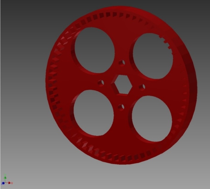 | Figure 6. Gear part upon its design completion in the CAD software |
|
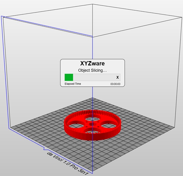 | Figure 7. Slicing process upon process parameter setting completion |
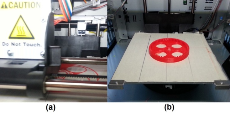 | Figure 8. (a): Part printing during first layer, (b): Printed part completed |
 | Figure 9. Parts A & B from left (part A) to right (part B) exhibiting variations in surface quality |
4. Optimal Parameter Settings Proposal
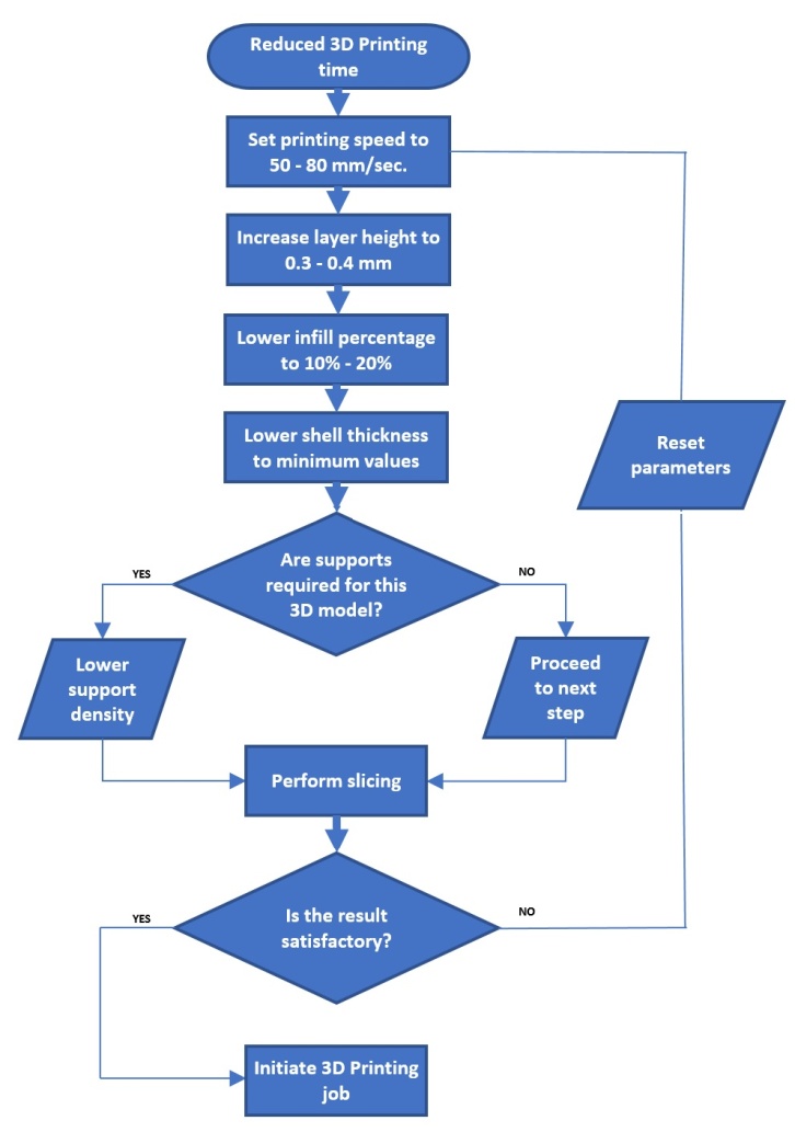
- In this section, authors would like to propose three different sets of 3D Printing process parameter settings leading to different scenarios. All scenarios will lead to acceptable 3D Printing results; however, they will be targeted to specific demands like time for the completion of the 3D Printing job, part strength and surface quality. The first group of settings has to do with achieving the fastest possible 3D Printing job, the second group of settings with the achievement of maximum part strength while the third group of settings will be targeted towards achieving increased surface quality. Each set of process parameters’ settings will be presented via a flow chart where the user should follow certain steps while re-evaluating his decisions towards reaching the optimal results.The first group of proposed parameters has to do with achieving a fast 3D Printing job while maintaining an acceptable aesthetical result for the fabricated item. Printing speeds in the range of 50-80 mm/sec are considered to be on the high end of the maximum FFF 3D Printers’ speeds but are considered to still provide sufficient part surface quality. Increased layer height along lower infill percentage and shell thickness values lead to faster 3D Printing completion times. Figure 10 depicts the proposed group of settings via a flow chart.
 | Figure 10. Proposed group of process parameter settings for achieving reduced 3D Printing time |
 | Figure 11. Proposed group of process parameter settings for achieving increased part strength |
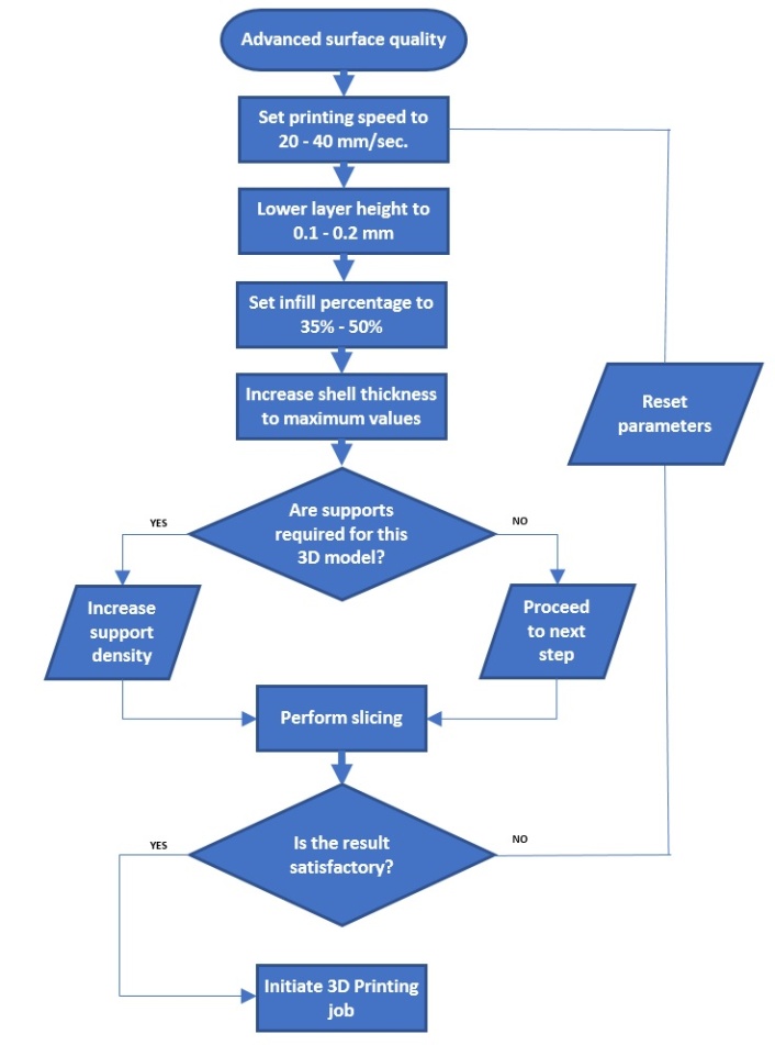 | Figure 12. Proposed group of process parameter settings for advanced surface quality |
5. Discussion
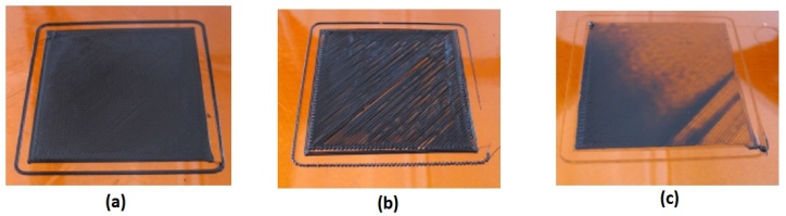
- The end-users of FFF category 3D Printers have to make a proper parameters’ setting in order to achieve the desired part printing quality. At the same time, printers of this category often are provided with limited capability processing/slicing software that does not offer many options regarding process parameter setting. Thus, users cannot surpass this inefficiency and end up with poor, or in best case intermediate, printing quality and printed parts that do not match the desired standards. Although this may be true, users can betake to other slicing software packages that are compatible with a broad range of FFF 3D Printers. Such slicing software packages offer the tuning ability of a great number of process parameters, thus, provide a greater potential for a good quality 3D Printing Job to be achieved. More specifically, such slicing software packages can be found and downloaded online. During the setup process the user is prompted to choose the 3D Printer model he uses in order for the software to be configured accordingly. Upon the completion of the setup process, the slicing software provides some initial, basic, process parameters’ profiles that are tested to offer acceptable quality prints. Such profiles can have names like “fast”, “medium” and high”, referring to auto-configurations for print quality in relation to printing speed. The user is also prompted to choose printing materials (PLA, ABS, PETG etc.) in order for the software to tune the temperature process parameter accordingly. However, apart from these initial, basic, process parameters’ profiles, users can choose to use the “advanced” configurations in order to further tune a large number of process parameters that may lead to greater quality prints. Such slicing software packages can be found available online, free of charge (CuraTM, Slic3rTM etc.) [31,32] or at a relatively low cost (Simplify 3DTM) [33]. However, all the aforementioned information relate to what can be achieved from the slicing software’s side. Another equally important aspect is the 3D Printer’s hardware condition. For example, a hardware parameter of paramount importance is the proper platform/nozzle distance calibration. The nozzle has to be set in a specific distance in relation with the platform in order to achieve the proper rheological material flow. Higher distance is linked with material detaching from the platform while shorter distance is linked with reduced nozzle flow that can lead to clogging phenomena. This can be depicted in figure 13 where (a) shows a proper calibrated 3D Printer hardware leading to good quality print, while (b) and (c) show printing result where the nozzle is not calibrated properly in accordance with the platform (greater distance for “b” and shorter distance for “c”).
 | Figure 13. Varied quality 3D prints, related with the proper nozzle/platform calibration |
6. Conclusions
- The aim of this article is to look into the printing results challenges that the users of a low-cost desktop 3D printer might possibly face and to investigate how to overcome them by tuning selected process parameters with immense contribution to the printing quality characteristics. 3D printing was initially introduced in order to overcome limitations in prototype fabrication. However, the maturation of this technology made it capable of producing end-use products and accessible to a continuously growing number of enterprises and individual users. Especially in the last years, the introduction of a reasonably priced, low cost, desktop FFF 3D printer range made the them really affordable for anyone to purchase. Yet, this technology was not freed from shortcomings. FFF 3D printers require a substantial user expertise in order to function properly and achieve the desired results. The maturation of 3D printing technology led to the simplification of the printing preparation process that, however, still demands a certain degree of process parameter contribution understanding to achieve an acceptable final printing result. In this context, process parameters that affect printing results are being thoroughly described in this article. To the authors’ opinion, layer height, infill percentage, printing speed, shell thickness, printing temperature, retraction and supports existence have immense contribution towards achieving desired printing results. The role of each parameter is discussed and a process parameter setting range is suggested in order to accomplish different demands like reduced 3D Printing time, increased part strength and advanced surface quality.In order to depict the possible part quality variations caused by different process parameter settings, a mechanical part design was selected to be printed in a low-cost desktop 3D printer whose purchase cost was under 1000$. The part was printed twice, with different process parameter settings each time. The differences on the 3D printing results were evident and indicative of the different settings followed, regarding aspects like part surface quality. However, different 3D Printing demands like reduced 3D Printing time, advanced part strength and advanced surface quality, dictate differentiated process parameter settings.In this context, this paper proposes three different groups of process parameter settings according to the aforementioned 3D Printing demands that are quite common among the 3D Printers’ end-users. By presenting a flow chart for each separate demand scenario, specific process parameter values are proposed within a specific value range. This range was selected taking into account small hardware variations between the FFF 3D Printers that might be used. In the end of each flow chart, users are encouraged to self-assess the results of the printing job and perform any parameter alteration within the values’ range proposed. However, often the slicing software packages that accompany FFF 3D Printers offer limited process parameter tuning choices. Therefore, users tend to migrate towards other, universal, slicing software packages that offer a broader choice of process parameter options to be tuned in order to achieve good quality prints. While this is, undoubtedly, a step towards improvement, users must spent a fair amount of time in order to understand each process parameter’s contribution to the part end-quality as well the possible interaction between them. In conclusion, the role of process parameters is substantial towards achieving successful 3D prints in the lower end of desktop FFF 3D Printers. The proper tuning of the aforementioned parameters is an important step towards overcoming challenges that raise some degree of skepticism and discourage users from adopting low-cost desktop 3D printers.