Ahmed Ketata, Zied Driss
Laboratory of Electro-Mechanic Systems (LASEM), National School of Engineers of Sfax (ENIS), University of Sfax, Sfax, Tunisia
Correspondence to: Ahmed Ketata, Laboratory of Electro-Mechanic Systems (LASEM), National School of Engineers of Sfax (ENIS), University of Sfax, Sfax, Tunisia.
| Email: |  |
Copyright © 2017 Scientific & Academic Publishing. All Rights Reserved.
This work is licensed under the Creative Commons Attribution International License (CC BY).
http://creativecommons.org/licenses/by/4.0/

Abstract
In purpose to improve engines emissions and its output torques, automotive manufacturers use boosting systems such turbochargers in which the turbine presents a critical component. This paper presents the numerical model for steady simulations of a mixed flow turbine. Simulations are done by solving Navier-Stokes equations using a finite volume method for the discretization. The swallowing capacity and the efficiency are plotted against the rotational speed of the turbine shaft in order to know its effect on the turbine operating capacity. Furthermore, reaction degree and rothalpy are computed for each operating condition to characterize the contribution of the rotor to the output work in the full turbine stage. To analysis the flow behavior at off-design conditions, distributions of the velocity and the pressure at different operating conditions are numerically obtained. A good agreement is found between computed results and test data confirming the validity of our numerical method.
Keywords:
CFD, Turbine, Performance, Energy, Efficiency
Cite this paper: Ahmed Ketata, Zied Driss, Numerical Study of a Vanned Mixed Flow Turbine Operating in Various Steady Flow Conditions, International Journal of Mechanics and Applications, Vol. 7 No. 1, 2017, pp. 24-30. doi: 10.5923/j.mechanics.20170701.03.
1. Introduction
More and more legislation was made to limit the emission of carbon dioxide from the exhaust of internal combustion engines. In order to respond to this environmental challenge, the employee of downsized engines by car manufactures contributes to reducing emissions of the engine exhaust gas. However, the downsizing technics requires commonly boosting systems such as a turbocharger which plays a key role in reducing engine fuel consumption. The radial turbine and the centrifugal compressor present fundamental components of an automotive turbocharger. The turbine expands the engine exhaust gas energy and drives it to the compressor by a shaft to boost the engine admission. The global trend consisted to enhance the turbine performance. Significant efficiency can be achieved for a high rotor speed, but when taking into account mechanical stresses, the speed of the rotor becomes limited. For this, the turbocharger turbine has to work with the maximum efficiency at a lower value of the blade speed corresponding to a velocity ratio different to the usual value for a radial inflow turbine which is about 0.707. To build a turbocharger with such requirement, a cho non-zero and a positive inlet rotor blade angle must be sen with maintaining radial blade fiber elements. Such impeller is called the mixed flow turbine rotor in which the flow streamline have radial and axial components at the rotor inlet. Abidat [1] is among the first who designed and studied such turbine rotor in the imperial college laboratory. Romagnoli and Martinez-Botas [2] performed a mean line model to predict the aerodynamic performance for a nozzleless and nozzled mixed flow turbine. Results were validated by test data over a wide range of the velocity ratio extracted from the imperial college test rig. This model allowed to give a good prediction of the turbine performance under steady-state conditions and to perform a breakdown loss analysis. Hamel et al. [3] performed a CFD investigation, using the CFX solver, for a mixed flow turbine under steady and unsteady conditions. They indicated the capability of the standard k-ε turbulence model and the frozen rotor approach to predict accurately turbine aerodynamic performance and to capture the flow fields within a mixed flow turbine. In addition, they marked a deviation of the instantaneous performance of the turbine from its steady-state value. Roclawsk et al. [4] conducted CFD simulations for a mixed flow turbine under steady and unsteady conditions. Their results show that a lower degree of reaction yields to the improvement of the turbine isentropic efficiency at higher pressure ratios. They noted equally that a greater blade loading and a smaller tip leakage loss could be achieved by reducing the degree of reaction.This paper presents our optimized numerical model in order to predict the steady-state performance of a vanned mixed flow turbine under different operating conditions. Firstly, the turbine geometry model and the meshing are developed. Then, the turbine performance maps are computed by solving the Reynolds Averaged Navier-Stokes (RANS) equations. A good agreement is found between our numerical results and the experiments. Equally, the degree of reaction and the rothalpy are computed for each operating conditions. Then, the distribution of the pressure and the velocity are obtained numerically at different operating conditions.
2. Numerical Method
The mixed flow turbine becomes more famous compared to the radial inflow turbine for automotive turbocharger applications. The mixed flow impeller is a combination of the radial and axial geometries. The rotor of the mixed flow turbine investigated in this present work is designed by Abidat [1]. The impeller blade shape is made with Polynomial Bezier curves giving different control points. The mixed flow turbine impeller consists of 12 blades with 40 mm of length. The inducer means the diameter of the turbine is 83.6 mm. However, its exducer hub diameter is 27 mm. The span height is fixed to be 18 mm at the inducer and 25.8 mm at the exducer. Its cone angle is 40° and its inlet blade angle is set to be 20°. However, it presents a variable exit flow angle keeping -52° as a mean value. The axial and radial tip clearances are fixed to be about 0.4 mm. The turbine inlet vane radius is 70 mm. On the other hand, we are interested in the nozzle-less configuration of the volute which is modified by Rajoo [5]. Its centroid throat radius and its throat area are respectively about 100 mm and 3300 mm2. However, its tongue position is set to be 50°. Figure 1.a presents the obtained design of the mixed flow impeller. Figure 1.b shows the developed three-dimensional model of the vanned nozzle-less volute.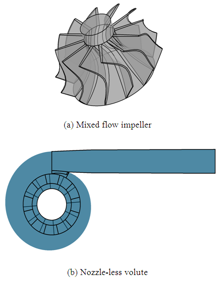 | Figure 1. CAD modeling |
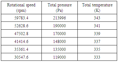
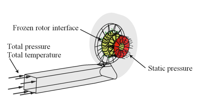
Conducted simulations are based on Reynolds averaged Navier-Stokes equations of mass, momentum, and energy conservation for compressible flow. The commercial Ansys CFX 17.0 which is a CFD package including a finite volume method for the discretization is used to resolve implicitly these equations with a pressure-based solver. The standard k-ε turbulence model is chosen to solve the additional terms which are due to the Reynolds decomposition. This turbulence model presented excellent capabilities to compute the flow in several anterior aerodynamic works [6, 7]. After that, the rotational and stationary domains are assembled together by means of a conical interface. At this interface, a frozen rotor approach was applied with a full pitch angle for both sides. In order to get a good description of the test rig conditions, a total pressure and a total temperature are imposed at the volute inlet boundary for each tested rotational speed. Figure 2 presents the full computational domain after the assembly and the different applied boundary conditions. Furthermore, an average static pressure is prescribed at the rotor exit boundary to avoid the creation of a reversed flow in the rotor exit. Table 1 resumes different involved boundary conditions at each rotor speed. Furthermore, a non-slip wall function is detailed for all wall boundaries such as the hub, the blades, the shroud and the volute walls. Particularly, a counter-rotating condition wall is defined at the shroud wall. Finally, zero values are affected to all parameters as an initial guess for the full computational domain.Table 1. Inlet boundary conditions
 |
| |
|
 | Figure 2. Computational domain and boundaries |
The accuracy of numerical results depends to a large extent on the quality of the mesh. Generally, the more the mesh was refined, more accurate results are obtained. Despite the requirement of results accuracy, the time of the simulation convergence is also an important criterion for industrial applications. In fact, the computational domain of the full turbine stage is divided into tetrahedral elements creating an unstructured meshing. The volute tongue interfaces, and turbine blades are refined more than other regions using the local meshing parameter of the Ansys software. A gradual cell size transition was kept for the zone separating between coarse and fine mesh regions. Three sizes of the meshing are generated by varying each time the cell size. The coarse meshing consists of 30287 cells and 9282 nodes when the medium meshing consists of 329619 cells and 106070 nodes. However, the fine meshing is composed of 1155129 cells and 2059178 nodes. Figure 3 shows the three-dimensional views of the meshing for the different sizes.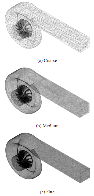 | Figure 3. Generated meshing |
3. Numerical Validation
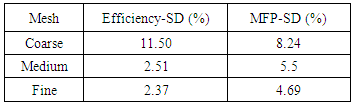
To validate the computational method, a comparison of the numerical results to test data, collected by Romagnoli et al. [2], is made at 59783.4 rpm of the rotational speed. For this end, we computed the Standard Deviation (SD) of the efficiency and of the mass flow parameter (MFP) at the optimum operating condition for the considered mesh sizes, as detailed in table 2. The MFP is computed as follows: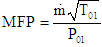 | (1) |
Where  is the mass flow rate,
  is the stagnation temperature at the turbine inlet, and
  is the inlet stagnation pressure.The turbine efficiency
  is given by the ratio of the actual power
  to the isentropic power
  as follows:
 | (2) |
For the coarse mesh, the standard deviations of the efficiency and the MFP are found to be 11.50% and 8.24% respectively. However, the deviations of the efficiency and the mass flow parameter decrease significantly to be 2.37% and 4.69% respectively when the fine mesh is used. From these results, it has been observed that the numerical prediction of the efficiency is more sensitive to the mesh size than that of the MFP. Besides, this deviation increases with the drop of the mesh size. Furthermore, this deviation stills in an acceptable range. Taking into account the limitations of our computational resources as well as the resolution time for the solution convergence, the medium mesh which consists of 329619 tetrahedral elements seems to be the best choice for predicting the turbine performance. Using this mesh size, the distribution of both the mass flow parameter (MFP) and the total to static isentropic efficiency are obtained as a function of the pressure ratio and the isentropic velocity ratio respectively as shown in figure 4. The isentropic velocity ratio is given as follows: 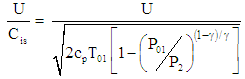 | (3) |
Where U is the blade tip speed, Cis is the spouting velocity,  is the specific heat ratio, cp is the specific heat capacity at constant pressure, and P2 is the outlet static pressure. The expansion ratio of the turbine is defined as the ratio of the inlet stagnation pressure to the outlet static pressure. From figure 4, the comparison of the numerical results to test data confirms the validity of the numerical model. In addition, it can be seen that the turbine efficiency decreases with the surge of the velocity ratio. However, the MFP presents an upward trend with the wake of the pressure ratio.
 Table 2. Deviation from experiments
 |
| |
|
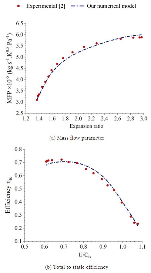 | Figure 4. Comparison to test data |
4. Results and Discussion
4.1. Mass Flow Rate
Figure 5.a presents the distribution of the mass flow parameter as a function of the expansion ratio for different operating conditions. Referring to these results, it has been noted that the mass flow parameter increases, with a nonlinear manner, with the increase of the pressure ratio for different rotational speeds. At higher pressure ratios, the mass flow parameter still nearly at the same level. At these conditions, the mass flow rate becomes approximately insensitive to the change of the pressure ratio. This limitation of the mass flow rate is referred to the choked flow which is a characteristic of the sonic blockage. Furthermore, any choking condition is observed for both 30547.6 rpm and 35361.4 rpm of the rotational speed. The maximum recorded value of the choking mass flow parameter is found to be 0.614 at 41414.6 rpm of the turbine speed. When the pressure ratio is fixed at a defined value, it can be clearly detected that the mass flow rate is greatly sensitive to the turbine speed. Indeed, the mass flow rate as well as the choking mass flow rate decreases significantly with the rise of the rotational speed. Figure 5.b shows the distribution of the choking mass flow parameter as a function of the rotational speed for the different operating conditions. From these results, it is evident that the choking mass flow rate depends considerably on the turbine speeds. In fact, the coking mass flow rate decreases significantly when the rotational speed gets an upward trend for a range of rotational speed from 40000 rpm to 60000 rpm.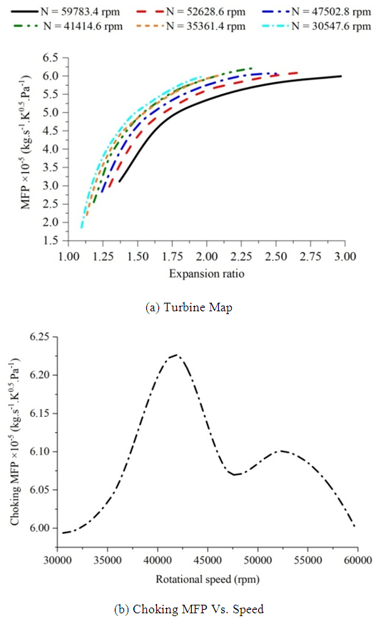 | Figure 5. Distributions of the mass flow parameter |
4.2. Efficiency
Figure 6.a presents the distribution of the total to static isentropic efficiency as a function of the isentropic velocity ratio for different rotational speeds. From these results, it has been observed that the total to static isentropic efficiency gets an upward trend when the velocity ratio decreases until it attains its maximum value. From this point, it returns to drop slightly. It can be seen that the peak efficiency occurs at a velocity ratio less than 0.7 which presents typically the point of the peak efficiency for a radial inflow turbine. Then, the mixed flow turbine works efficiently at lower velocity ratios compared to the radial configuration. From 41414.6 rpm to 59783.4 rpm, the efficiency remains at the same level for a velocity ratio higher than 0.85. The same observation is obtained from 30547.6 rpm to 35367.4 rpm for a velocity ratio higher than 0.6. However, the isentropic efficiency becomes significantly more sensitive to the rotational speed for lower velocity ratios. In order to evaluate the effect of the operating conditions on the turbine stage performance, the peak efficiency is plotted as a function of the rotational speed as shown in figure 6.b. From these results, it is worth noting that the peak efficiency depends greatly on the rotational speed. From the lowest rotor speed, the peak efficiency gets an upward trend until it achieves its maximum value which is about 0.74 at 44000 rpm. At this operating condition, the turbine seems to recover the maximum possible amount of the available exhaust gas energy. Outside this operating point, the peak efficiency decreases slightly with the rise of the rotational speed. 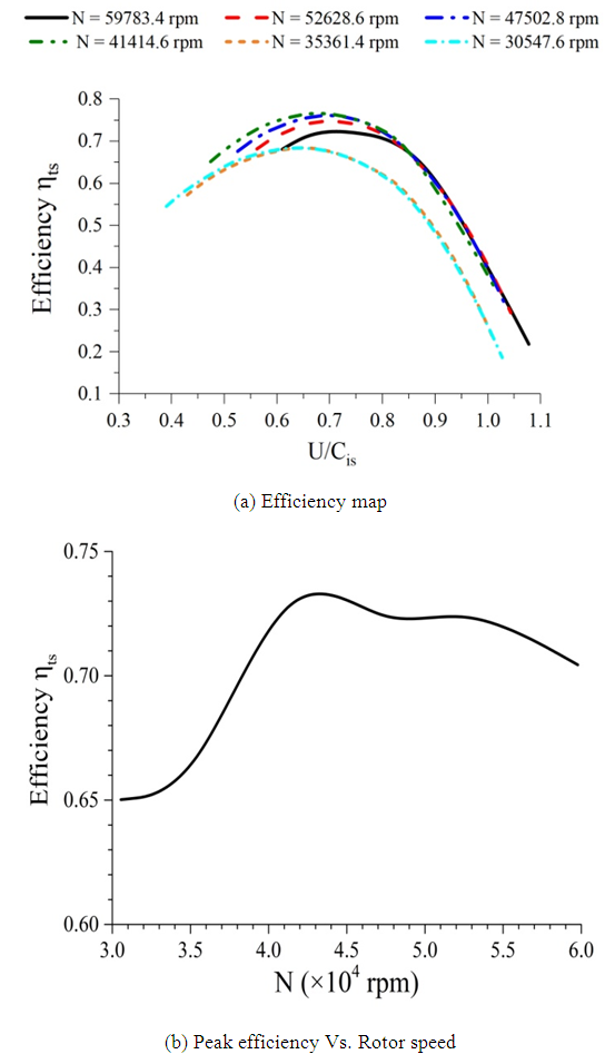 | Figure 6. Total-to-static isentropic efficiency |
4.3. Turbine Work
The degree of reaction is a thermodynamic parameter, which characterizes the contribution of the rotor to the total enthalpy drop within the full turbine stage. Then, the reaction degree is defined as the ratio of the enthalpy change within the rotor to the total enthalpy change within the full stage of the turbine: | (4) |
Figure 7.a presents the distribution of the degree of reaction as a function of the velocity ratio at different rotational speeds. From these results, it has been observed that the value of the degree of reaction varies significantly with the change of the velocity ratio and then, with the pressure ratio for different speeds of the rotor. In fact, at a fixed value of the rotational speed, the degree of reaction decreases gradually with the rise of the isentropic velocity ratio from its lowest value. Once a minimum value is reached, the degree of reaction gets an upward trend with a sharp slope. Furthermore, it has been observed that the reaction degree presents approximately the same value for different speeds of the rotor at a fixed value of the velocity ratio higher than 0.9. However, the degree of reaction is found to be exceedingly sensitive to the rotor speed for velocity ratios less than 0.9. In this case, the rise of the rotational speed yields to the growth of the reaction degree. Thus, the contribution of the mixed flow rotor to the enthalpy drop within the full turbine stage is more important at higher rotational speeds. Figure 7.b presents the distribution of the rothalpy, which is a contraction of rotational stagnation enthalpy, as a function of the rotational speeds. From these results, it has been observed that the rotational stagnation enthalpy drops considerably as the rotational speed grows. This fact is due essentially to the substantial increase of the impeller blade speed. At lower speeds when the rothalpy takes positive values, the static enthalpy in the relative frame is found to be higher than the kinetic energy due to impeller movement. However, the relative static enthalpy is expected to be lower than the kinetic energy due to the rotation of the rotor at negative values of the rothalpy.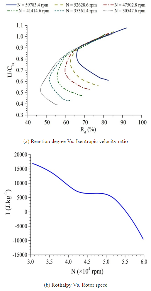 | Figure 7. Contribution of the rotor to the available work |
4.4. Velocity
Figure 8 presents the velocity streamlines colored by the relative velocity magnitude at the plane defined by 50% of the span-wise length. These streamlines are obtained at the peak efficiency point for the different rotational speeds of the turbine impeller. From these results, a passage vortex, which is due mainly to the impeller tip leakage flow, can be easily detected near the shroud region for each tested operating condition. This fact leads to a flow disturbance, which is found to be larger at lower than higher rotational speeds, around the vortex zone. In fact, this flow disturbance leads to an occurring aerodynamic loss within the blade passage. Furthermore, a flow separation is detected at the pressure surface near the blade tip which is due to the presence of the passage vortex. This flow separation becomes more important when the rotational speed drops. Referring to figure 8, it is worth noting that the relative velocity magnitude gets significant values when the rotational speed grows. Moreover, it is obvious that the relative velocity magnitude is higher at the suction surface of the rotor blades compared to that at the pressure surface. However, it can be noted that the relative velocity presents greater values near the shroud than near the hub at the different blade to blade positions of the impeller passage. So, it is expected that the relative velocity magnitude gets a downward trend across the span length of the rotor. For thus, a wake zone characteristic of the maximal values of the relative velocity magnitude has been observed at the suction surface near the shroud.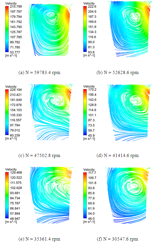 | Figure 8. Distribution of the relative velocity streamlines |
4.5. Pressure
Figure 9 presents the distribution of the static pressure at the plane defined by 50% of the span-wise length. These distributions are computed at the operating point defined by the maximum efficiency for different rotational speeds of the rotor. Referring to these results, a wake zone characteristic of the maximum values of the static pressure has been observed at the pressure surface of the turbine blades. This region is found to be larger at lower rotational speeds. Furthermore, it can be seen that the value of the static pressure decreases gradually across the span length from the shroud to the hub. Moreover, a zone characteristic of the minimum values of the static pressure is clearly recognized at the suction surface. This area becomes greater when the rotational speed increases. The difference between values of the static pressure at the suction surface and the pressure surface is found to be significant at higher rotational speeds. Thus, it can be deduced that the blade loading becomes more important at higher rotational speeds.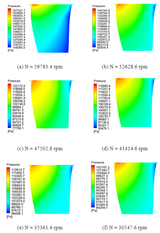 | Figure 9. Distribution of the static pressure |
5. Conclusions
This paper discusses the effect of the different operating conditions on a mixed flow turbine aerodynamic performance. Conducted simulations are based on the resolution of the Reynolds averaged Navier-Stokes equations with a finite volume method for the discretization. Three unstructured meshing sizes are generated for the grid independency analysis. The numerical results are significantly sensitive to the mesh resolution. The reasonable agreement found between numerical and experimental results ensures our numerical model validation. Based on the computed standard deviation of the numerical results from experiments, the medium mesh which consists of 329619 tetrahedral cells seems to be able to predict well the turbine performance. Further, the turbine performance significantly depends on the rotational speed and its expansion ratio. Besides, the peak efficiency occurs at an optimum isentropic velocity ratio less than 0.7 which presents the advantage of the mixed flow turbine compared to the radial turbine. Furthermore, the reaction degree is considerably influenced by the variation of the isentropic velocity ratio. Equally, a flow separation has been noted at the blade tip pressure surface which is due to the presence of the passage vortex. This vortex contributes significantly to the flow disturbance within the rotor passage which generally leads to the deterioration of the turbine performance. The blade loading is found to be sensitive to the operating condition, and it comes to be more advanced at greater speeds of the turbine shaft.
Abbreviation
References
| [1] | M. Abidat, Design and testing of a highly loaded mixed flow turbine, PhD thesis, Imperial College, London, 1991. |
| [2] | A. Romagnoli, R.-F. Martinez-Botas, Performance prediction of a nozzled and nozzleless mixed-flow turbine in steady conditions, International Journal of Mechanical Science 53, 2011, pp 557–574. |
| [3] | M. Hamel, M. Abidat, S.A. Litim, Investigation of the mixed flow turbine performance under inlet pulsating flow conditions, C. R. Mecanique 340, 2012, pp 165-176. |
| [4] | H. Roclawski, M. Gugau, F. Langecker, M. Böhle, Influence of degree of reaction on turbine performance for pulsating flow conditions, Proceedings of the ASME Turbo Expo, 2014. |
| [5] | S. Rajoo, Steady and Pulsating Performance of a Variable Geometry Mixed Flow Turbochager Turbine, PhD thesis, Imperial College, London, 2007. |
| [6] | Z. Driss, O. Mlayeh, S. Driss, D. Driss, M. Maaloul, M. S. Abid, Study of the incidence angle effect on the aerodynamic structure characteristics of an incurved Savonius wind rotor placed in a wind tunnel, Energy 894, 2016, pp 908-113. |
| [7] | Z. Driss, O. Mlayeh, D. Driss, M. Maaloul, M. S. Abid, Numerical simulation and experimental validation of the turbulent flow around a small incurved Savonius wind rotor, Energy 74, 2014, 506-17. |

 Abstract
 Reference
 Full-Text PDF
 Full-text HTML