-
Paper Information
- Paper Submission
-
Journal Information
- About This Journal
- Editorial Board
- Current Issue
- Archive
- Author Guidelines
- Contact Us
International Journal of Mechanics and Applications
p-ISSN: 2165-9281 e-ISSN: 2165-9303
2017; 7(1): 14-23
doi:10.5923/j.mechanics.20170701.02

3D ANSYS Numerical Modeling of Reinforced Concrete Beam Behavior under Different Collapsed Mechanisms
 Abstract
 Reference
 Full-Text PDF
 Full-text HTML
Darmansyah Tjitradi, Eliatun Eliatun, Syahril Taufik
Civil Engineering Department, Lambung Mangkurat University, Banjarmasin, Indonesia
Correspondence to: Syahril Taufik, Civil Engineering Department, Lambung Mangkurat University, Banjarmasin, Indonesia.
| Email: |  |
Copyright © 2017 Scientific & Academic Publishing. All Rights Reserved.
This work is licensed under the Creative Commons Attribution International License (CC BY).
http://creativecommons.org/licenses/by/4.0/

This paper discusses about 3D ANSYS FE modeling of the failure behavior of structural reinforced concrete beam element. The capacity of the bending moment, deformation, stress, strain and fracture patterns is determined that occurs on a single reinforced concrete beams with different types of collapsed mechanisms. The RC beam specimens of normal strength is modeled by rectangular section with tensile steel reinforcement ratios to represent the tensile, balanced, and compressive collapsed mechanism. The beams is subjected to concentrated load at middle span and collapsed behavior observed from load of the first crack up to fully collapse. The results show that the reinforced concrete beams can be analyzed using ANSYS software with modified model. The behavior of reinforced concrete beams can be determined by the analysis of calculation and FEM that beams with tensile collapsed condition has a lower flexural capacity and collapse behavior is more ductile than that of the beam with the compressive collapse and balanced condition. According to SNI 03-2847 manual calculation analysis is more suitable to represent the RC beam behavior of collapsed condition.
Keywords: Concrete beam, Tensile collapse, Compressive collapse, Balanced collapse, ANSYS, FEM
Cite this paper: Darmansyah Tjitradi, Eliatun Eliatun, Syahril Taufik, 3D ANSYS Numerical Modeling of Reinforced Concrete Beam Behavior under Different Collapsed Mechanisms, International Journal of Mechanics and Applications, Vol. 7 No. 1, 2017, pp. 14-23. doi: 10.5923/j.mechanics.20170701.02.
Article Outline
1. Introduction
- Concrete beam has a weakness in terms withstand tensile, it is used to increase its strength of steel reinforcement fibers are mounted on a regional attraction. The addition of tensile reinforcement in concrete beams will cause different patterns of concrete collapse happened. Understanding the behavior of the collapse of a reinforced concrete beam is very important especially in the design phase of structural elements. In the design of a flexural beam, tensile reinforcement must be designed to meet the requirements of ductility so that the collapse happened is the ductile tension collapse, and should be avoided reinforcement design with an emergent brittle compression collapse. From the analysis on single reinforced concrete beams obtained that the ductility of the beam will decrease as tensile reinforcement ratio increase [1].To ensure that the design of the reinforcement behave ductile, tensile reinforcement ratio should be between the minimum and maximum reinforcement ratio required by the codes either SNI 03-2847-2013 [2] or ACI 318 [3]. Limiting reinforcement ratios for RC flexural members have significance influence on the crack behavior [4]. The RC design becomes more economicalby reducing not only the amount of reinforcement but also the installation of reinforcement junction [5].There are many methods for modeling the behavior of concrete structures through analytical and numerical approaches [6-8]. Finite Element Method (FEA) is one of the numerical methods are widely applied in concrete structures based on nonlinear behavior of materials. FEA provides tools to simulate and predict the behavior of reinforced and prestressed concrete elements, such as ANSYS [9].Numerical investigation of the behavior of normal strength concrete beam with single layer reinforcement by collapse patterns have been conducted using ANSYS software and can visualize the process of normal strength concrete beam collapse started from the first crack, yielding crack and ultimate cracking condition. A test on a simple beam two pedestals in the laboratory has been conducted and modeled with ANSYS computer-based modeling software. ANSYS can be an excellent alternative apart from damaging the laboratory tests, the variation of which is still acceptable [10, 11].Experimental study of the failure behavior of concrete beams normal quality has been done by taking the variation of the ratio of reinforcement tensile steel to represent three patterns of collapse with the result is the stress that occurs at the steel reinforcement fascination with pattern collapse of tensile (under reinforced) have reached the yield tension stress (fy = 415 MPa), the pattern collapse balanced 97% of yield stress, and pattern collapse of yield stress reaching 87%, this indicates that the larger the tensile steel reinforcement ratio the stress that occurs at tensile steel reinforcement will be smaller so that the beam will increasingly behave brittle [12]. The use of ANSYS software is very good to know the process of collapse a reinforced concrete beam flexural cracks start to the shear cracks (linear), but the result is having a significant deviation in the phase of destruction of concrete (plastic). However, this shortcoming can be overcome by using multilinear plasticity material models available in ANSYS [13]. In this research will study the behavior of structural elements of single layer reinforced concrete beam under tension, balanced, and compressive collapsed mechanisms to be modeled and analyzed using ANSYS software [14], and compared to manual analysis by code SNI 03-2847-2013. The parameters used in the modeling are the strength of concrete beams, steel quality, diameter steel reinforcement and static loading. Results to be obtained from this study was to determine collapse behaviour of the RC beam by the bending capacity, load-deformation relationships, stress-strain relation-ship of concrete and cracking patterns that occur in every model of the beam.
2. Model Configuration
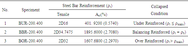
- A simple span reinforced concrete beam is modeled with applying ultimate pointload until crushing representing the reinforced concrete collapsed mechanism with conditions of under reinforced (ρ ≤ 0.75.ρb), balanced reinforced (ρ =. ρb) and over-reinforced (ρ > 0,75.ρb) with dimensions: 200 mm x 400 mm, L = 3000 mm, and Lc/c = 2800 mm (see Figure 1 and Table 1). The load is applied to the middle span beams with concentrated loads, and the observed value of the load, deflection, and the concrete stress that occurred from the first crack load up to fully collapse.
|
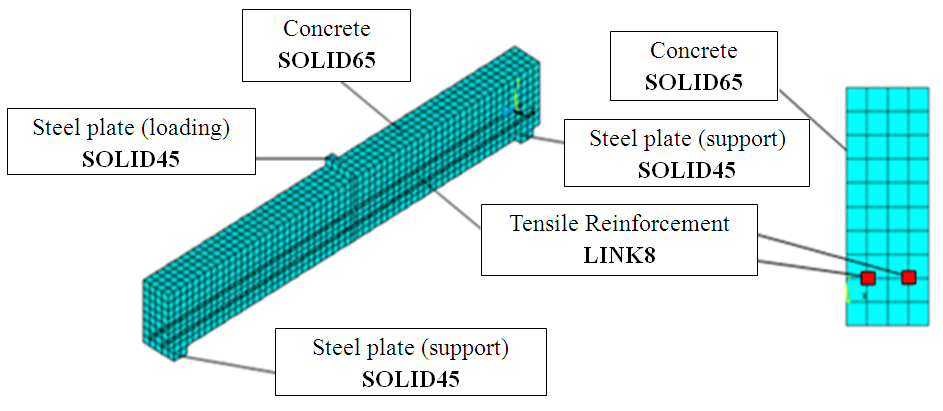 | Figure 1. Element Types of ANSYS Modeling |
3. Numerical Modeling
3.1. Reinforced Concrete Beam
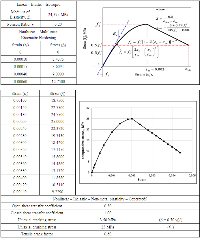
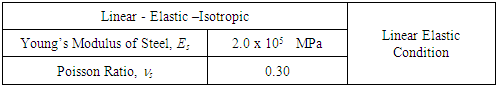
- A reinforced concrete beam material is modeled by 8 node solid elements (SOLID65) with three degrees of freedom at each point and the case of translation in the x, y, and z. This element also has the ability to deform plastically, cracks in the direction of x, y, and z, until the crushed concrete [15]. Normal strength quality concrete model used is a model of Multininear Kinematic Hardening by compression stress-strain curves of unconfined concrete proposed by Kent-Park and tensile stress is ft = 0.7.√fc’ [16-18] as shown in Table 2. The use of the element type SOLID65 in modeling of concrete materials can provide results either through the nonlinear behavior of reinforced concrete beams [19].
|
3.2. Steel Reinforcement
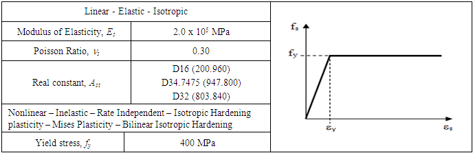
- Steel bar reinforcement in idealized as axial rod element by taking the discrete engineering models Spar Link Element (LINK8) with similar characteristics as the original, but a line reinforcement [20-23]. This element has 2 points with 3 degrees of freedom at any point in the x, y, and z, and is able to deform plastically. The reinforcement is assumed to be capable of transmitting axial forces only, and perfect bond is assumed to exist between the concrete and the reinforcing bars. To provide the perfect bond, the link element for the steel reinforcing bar was connected between nodes of each adjacent concrete solid element, so the two materials share the same nodes. Model of stress-strain relationship of steel used is a model Bilinear Isotropic Hardening that the material data is shown in Table 3.
|
3.3. Steel Plates Pedestal and Supports
- The steel plate used as the basis of concrete pedestal and supports that do not experience excessive local stress concentration which would cause the process to stop running ANSYS. These elements have 8 nodes with 3 degrees of freedom at any point in the x, y, and z [21]. The steel plates using a model SOLID 45 with the material conditions of linear data that can be seen in Table 4.
|
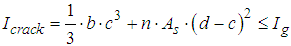
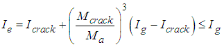
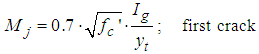
3.4. Hand Calculation
- According to analysis of SNI to determine capacity and deformation values of beam under the loading of first crack, yieid, and ultimite based on the equations:
 | (1) |
 | (2) |
 | (3) |
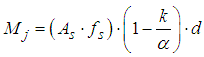 | (4) |
 | (5) |
 | (6) |
4. Results and Discussion
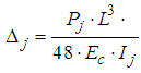
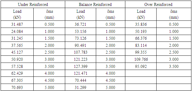
4.1. Load and Deflection
- The results of hand calculation analysis according to SNI and FEA ANSYS show the same behavior. From Table 5 and Figure 2, and Table 6 and Figure 3 it can be seen that the value of the load and deflection at the time of the first crack for the third type of collapse together, and seen that beam with the conditions of the collapse of the drop after the first crack occurs then tilt stiffness of the beam continues to decline (ductile), while the collapse of the press and balanced stiffness of the beam is only slightly decreased (brittle). From Figure 5 obtained from analysis of SNI for all models with the first crack loading of reaching 26.667 kN. From Figure 6 for ANSYS modelling with first crack loading reaching value of 31.487 kN (BUR-200.400), 36.721 kN (BBR-200.400), and 35.836 kN (BOR-200.400) with various values of mid span deflection (δms).
|
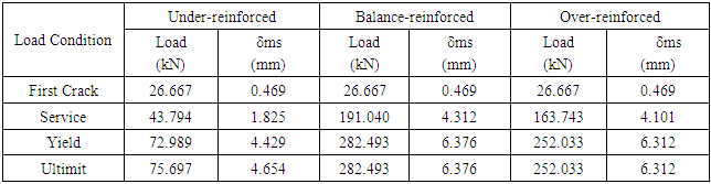
 | Figure 2. Results of Load-Deflection Analysis Manual According to SNI 03-2847 |
|
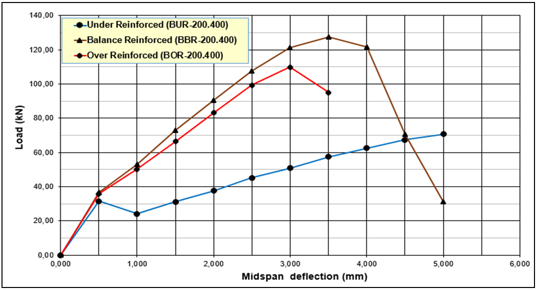 | Figure 3. FEA Load-Displacement with Various Reinforcement Ratio |
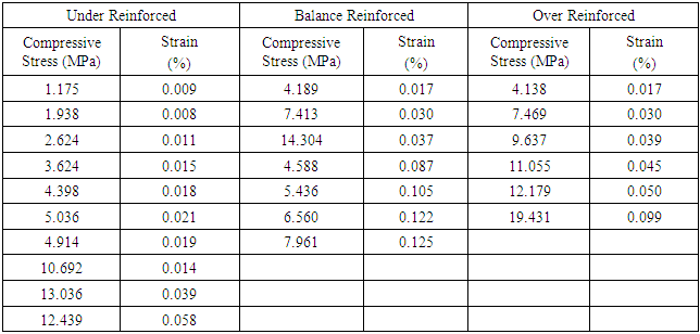
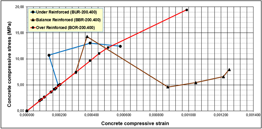
4.2. Compressive Stress and Strain
- FEA results of compressive stress and strain analysis of concrete is shown on Table 7 and Figure 4. It can be determined the mid span deflection that on the same value of 1.5 mm (row 3 in Table 7) after first crack occurred that the higher tensile reinforcement ratio, the higher the compressive stress of the concrete on the balanced reinforcement, so that the beam will be more brittle behavior.
|
 | Figure 4. FEA Results of Compressive Stress and Strain |
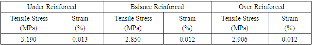
4.3. Tensile Stress and Strain
- From Table 8 and Figure 5 it can be seen that the condition has a tensile collapse concrete tensile stress most is equal to 3.190 MPa (tensile stress theory of ft = 3.50 MPa) compared to the collapse of the press and balanced condition. So it can be concluded that the higher tensile reinforcement ratio the tensile stress that occurs will be even lower.
|
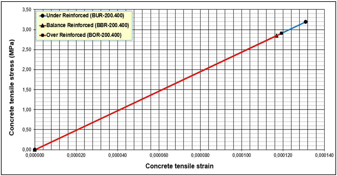 | Figure 5. FEA Results of Tensile Stress - Strain |
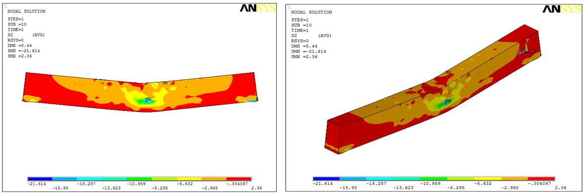
4.4. Visualization Stress Collapse
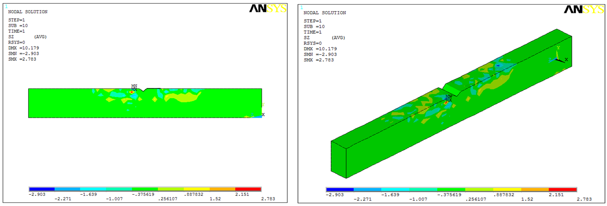
- From Figure 6 to 8, it can be visualized overall contour concrete beam voltage at the load end of the collapse, and it is known that the collapse of the balanced beam with a pattern of concrete compressive stress occurs higher due to brittle compared with the type of collapse tap, and ductile. Under reinforced beam is subject to development of bending stress spreading from the tension region to the compressive region, whilst the shear stress moiving to the support region. Balanced reinforced and over reinforced beams are subject to little development of the concrete from tension region to the compressive region, but the collpase mechanism happened due to high stress concentration on the mid span region. Therefore, concrete is failed under ultimate load with crushed brittle collapse mechanism.
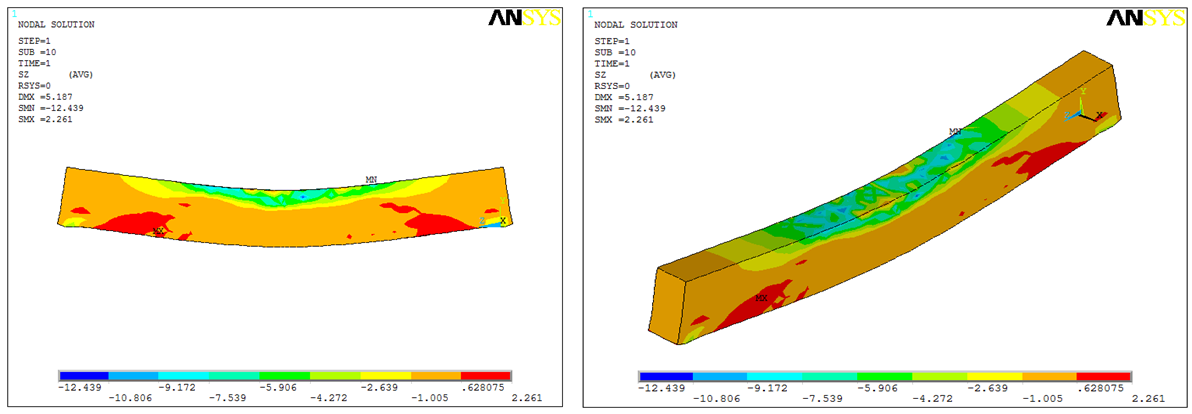 | Figure 6. Stress Contour of the Beam under Tensile Collapsed Mechanism (BUR-200.400) |
 | Figure 7. Stress Contour of the Beam under Balance Collapsed Mechanism (BBR-200.400) |
 | Figure 8. Stress Contour of the Beam under Compressive Collapsed Mechanism (BOR-200.400) |
4.5. Crack Patterns at Final Collapse
- Based of FEA ANSYS can be known pattern of cracked concrete at the time of the final collapse of the collapse of the state visit, press and balanced. From Figure 9 to 11 can be seen that the higher the ratio of tensile steel reinforcement beam bending, the capacity will be increased and the beam will behave more brittle, so that the destruction process in the area of concrete compressive (crushing) will be more visible.
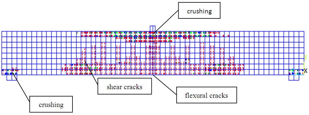 | Figure 9. Crack Pattern under Tensile Collapsed Mechanism (BUR-200.400) |
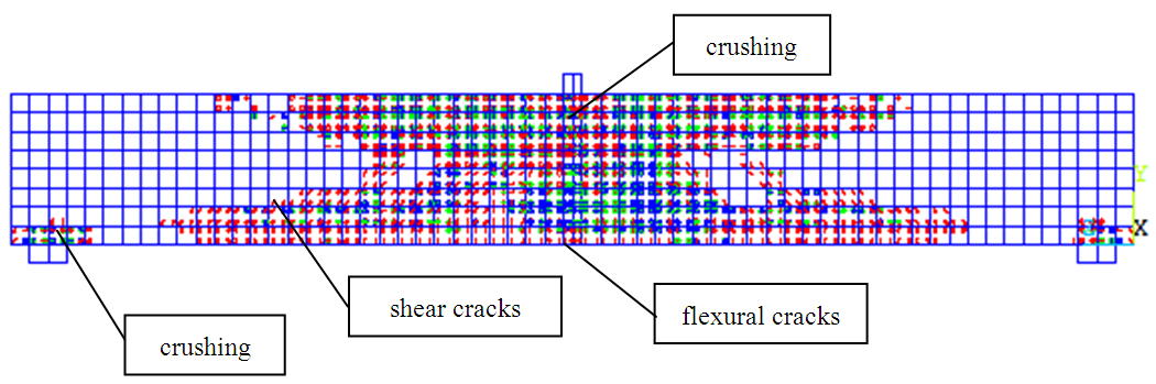 | Figure 10. Crack Pattern under Balance Collapsed Mechanism (BBR-200.400) |
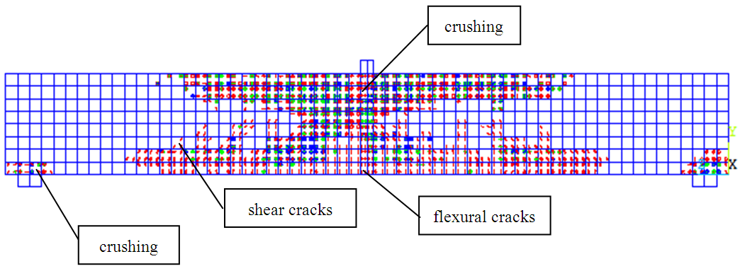 | Figure 11. Crack pattern under Compressive Collapsed Mechanism (BOR-200.400) |
5. Conclusions
- The conclusions of this study based on 3D numerical modelling analysis are:1) Single reinforced concrete beams with various conditions represented collapse with tensile reinforcement ratio variation can be modeled using 3D modified numerical modeling with spar element.2) Beams with pull collapse condition has a lower flexural capacity and collapse behavior is more ductile than the beam with the collapse of the compressive and balanced condition 3) The higher the ratio of tensile reinforcement beams, the process of collapse in the area of concrete compressive (crushing) will be more visible4) The higher the tensile reinforcement ratio the tensile stress that occurs, the lower yield stress.5) In the beam with the drop collapse condition, results of manual analysis according to SNI 03-2847 when the condition first crack load and ultimate load suitable for beams with tensile collapse condition (ρ ≤ 0.75.ρb) is closer to the result of FEA ANSYS
ACKNOWLEDGMENTS
- The financial support of the research grant from Lambung Mangkurat University is gratefully appreciated.