-
Paper Information
- Previous Paper
- Paper Submission
-
Journal Information
- About This Journal
- Editorial Board
- Current Issue
- Archive
- Author Guidelines
- Contact Us
International Journal of Mechanics and Applications
p-ISSN: 2165-9281 e-ISSN: 2165-9303
2016; 6(2): 31-38
doi:10.5923/j.mechanics.20160602.03

Numerical Study on the Liquid Sloshing in a Battery Cell Equipped with New Baffle Design
 Abstract
 Reference
 Full-Text PDF
 Full-text HTML
Abdallah Bouabidi, Zied Driss, Mohamed Salah Abid
Laboratory of Electro-Mechanic System (LASEM), National School of Engineers of Sfax (ENIS), University of Sfax, Sfax, Tunisia
Correspondence to: Zied Driss, Laboratory of Electro-Mechanic System (LASEM), National School of Engineers of Sfax (ENIS), University of Sfax, Sfax, Tunisia.
| Email: |  |
Copyright © 2016 Scientific & Academic Publishing. All Rights Reserved.
This work is licensed under the Creative Commons Attribution International License (CC BY).
http://creativecommons.org/licenses/by/4.0/

In this work, we are interested on the study of the mixing element effect on the hydrodynamic structure of the battery cell subjected to an external sinusoidal excitation. Particularly, we have investigated the liquid motion in four deigns of cell, the unbaffled cell, the cell with vertical baffle and the cell with two designs of mixing element. The governing equations were solved numerically using the software “Fluent” to determine and describe the local characteristics of the flow fields. The distribution of the velocity, the pressure as well as the turbulence characteristics for the different designs of the battery cells were presented and discussed. The results show that the mixing element affects considerably the hydrodynamic structure of the battery cell and confirm the efficacity of the use of the mixing element in the new design of the battery cell.
Keywords: Battery cell, CFD, Modelling, Turbulent flow, Finite volume, VOF
Cite this paper: Abdallah Bouabidi, Zied Driss, Mohamed Salah Abid, Numerical Study on the Liquid Sloshing in a Battery Cell Equipped with New Baffle Design, International Journal of Mechanics and Applications, Vol. 6 No. 2, 2016, pp. 31-38. doi: 10.5923/j.mechanics.20160602.03.
Article Outline
1. Introduction
- The phenomenon of liquid sloshing is defined as a time dependent fluid motion with free surface in a container oscillating along the horizontal direction perpendicular to the gravity. This phenomenon is studied numerically and experimentally in a great amount of works. For example, Popov et al. [1] studied the phenomenon of liquid sloshing in a cylindrical container. Zhang et al. [2] investigated the sloshing in an elastic container for different values of frequency. Bouabidi et al. [3] analyzed the effect of the vertical baffle height to suppress the sloshing violence in the partially filled container using the CFD. The study confirmed that the sloshing decreases with the increase of the baffle height. Chen et al. [4] developed a finite-difference method to investigate the sloshing in tanks. The effects of the frequency and the Reynolds number were investigated. Papaspyrou et al. [5] studied the sloshing phenomenon in a cylindrical container submitted to longitudinal excitation. Bouabidi et al. [6] studied of the time step size effect on the numerical simulation of sloshing. They compared their numerical results with the experimental results. They showed that the choice of the optimum time step value leads to a good agreement for the comparison of the numerical and the experimental results. Battaglia et al. [7] studied numerically the problem of free surface using the moving mesh technique. Belakroum et al. [8] studied the effect of baffles on the liquid sloshing phenomenon in tanks. Bouabidi et al. [9] studied the liquid sloshing in a battery cell with mixing element partially filled with liquid using the commercial CFD code “Fluent”. They studied the pumping phenomena under pressure variation in the tank. A test bench was developed to investigate the sloshing experimentally in the battery cell. The comparison between the numerical and the experimental results showed a good agreement. Bouabidi et al. [10] carried out a series of experiments to study a hydrostatic pump in a partially filled container. To understand the source of the hydrostatic pump, they performed a CFD simulation to predict the static pressure distribution generated in the container under sloshing loads. In another work, Bouabidi et al. [11] conducted a series of numerical simulations to investigate the effect of the external excitation frequency. They used the VOF (volume of fluid) model to resolve the two phase problem. Their study confirmed that the sloshing behavior depends on the frequency value. In fact, the sloshing loads increase with the frequency increase.In the present work, we are interested on the study of the mixing element effect in the lead acid battery cell. The commercial software "Fluent" was used to develop a 3D incompressible viscous two phase flow in a battery cell partially filled with liquid.
2. Geometrical Arrangement
- In this paper, a battery cell with mixing element developed by Ebner et al. [12] is considered. It consists of three baffles, two vertical baffles and one horizontal baffle. The geometrical parameters are given in figure 1. To study the effect of the mixing element, we start by the study of the sloshing phenomenon in a rectangular tank. Then, we investigate the effect of a conventional vertical baffle. Finally, we examine the effect of two designs of mixing element. The topless battery cell is partially filled with a fluid. To study the hydrodynamic structure, it is assumed that that the fluid is the water with a density equal to ρ=1000 kg.m-3.
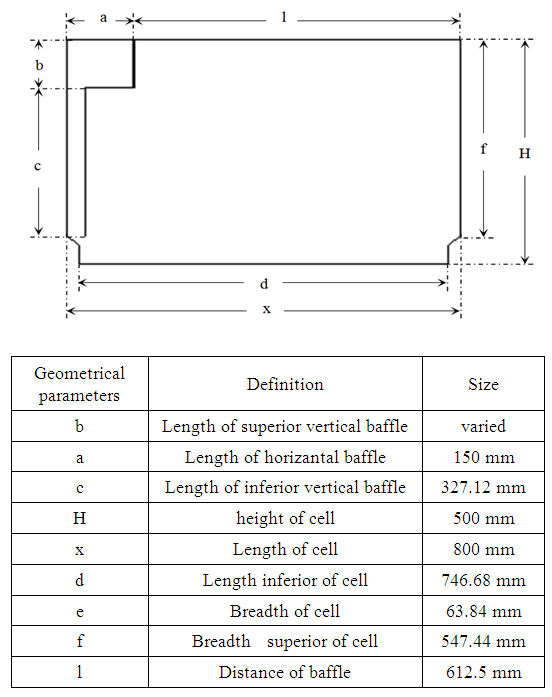 | Figure 1. Geometrical arrangement |
3. Numerical Model
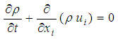
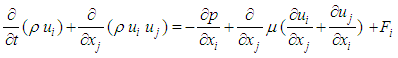
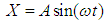
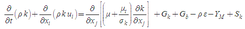
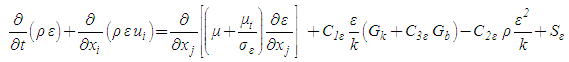
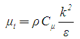
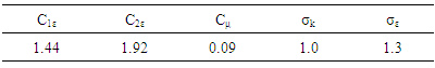
- The numerical simulation of the sloshing is developed using the commercial software "Fluent". To study the two phases problem (water and air), the VOF (Volume Of Fluid) is used. The motion function is developed as a UDF (User Defined Function). The UDF is developed in language “C++” and interpreted in “Fluent” as a source term for the fluid. The turbulence model is the standard k-ε. The Navier-Stokes equations in conjunction with the standard k-ε turbulence model are solved using a finite volume discretization method.The Navier–Stokes equations can be written in Cartesian form as:
 | (1) |
 | (2) |
 | (3) |
 | (4) |
 | (5) |
 | (6) |
 | (7) |
 | (8) |
|
4. Results and Discussions
4.1. Free Surface Evolution
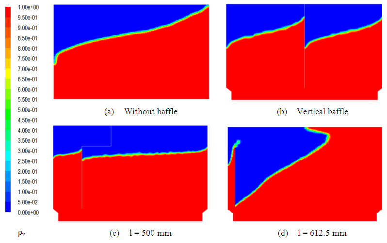
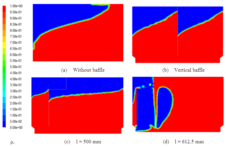
- The present application is a two phase problem. Over time, each phase is presented by its volume fraction. Figures 2, 3, 4 and 5 present respectively the free surface deformation for the different battery cell designs at t=0.001 s, t=0.1 s, t=0.8 s and t=0.9 s. According to these results, it is clear that the behavior of the sloshing is affected by the use of the vertical baffle and also by the use of the two mixing elements designs. At t=0.001 s, it has been observed that the sloshing of the liquid is very important for the unbaffled cell than for the three other designs. At t=0.9 s, the maximum free surface deformation has been observed for all different designs. For the fourth design of the cell, the sloshing of liquid is very important at t=0.8 s and at t=0.9 s than the others cases. According to these results, we can confirm that the effect of the baffle on the hydrodynamic structure of the cell is able to eliminate the acid stratification in the lead acid battery, which is not the case when using the conventional cell.
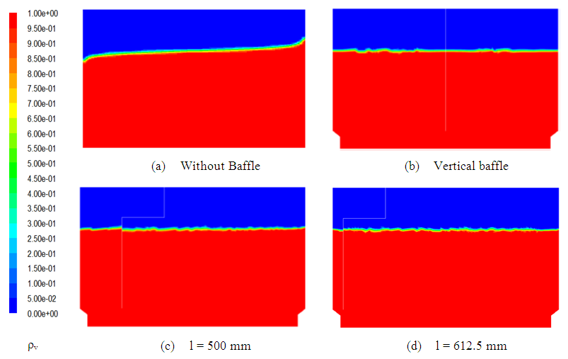 | Figure 2. Distribution of the volume fraction of liquid at t = 0.001 s |
 | Figure 3. Distribution of the volume fraction of liquid at t = 0.1 s |
 | Figure 4. Distribution of the volume fraction of liquid at t = 0.8 s |
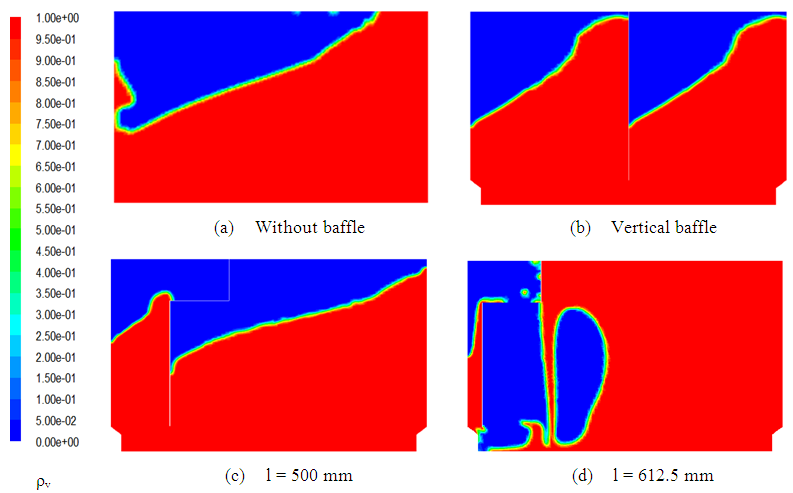 | Figure 5. Distribution of the volume fraction of liquid at t = 0.9 s |
4.2. Velocity Field
- Figure 6 presents the velocity fields for different designs of the battery cell at t=0.1 s. According to these results, it is clear that the velocity field is strongly affected by the baffle. With the three baffled cells and compared with the case of the conventional cell, an accelerate movement of the flow has been noted. For the standard cell, a largest recirculation zones appear on the free surface. In the case of the vertical baffle, two recirculation zones appear on the free surface. Also, a small recirculation zones has been observed in the bottom of the tank. Therefore, the use of the vertical baffle can be able to create a turbulence zone on the whole volume of the liquid. For the cell with mixing element with l = 500 mm, a largest recirculation zones appear on the free surface of the liquid. In this case, many recirculation zones appear on the whole volume of the liquid. The second case of the mixing element l=612.5 mm is also characterized by small recirculation zones on the whole volume of the liquid. The apparition of these recirculation zones on the bottom of the cell confirms that the use of the mixing element affects considerably the hydrodynamic structure of the cell. For the different cases, it has been observed that the velocity is very weak at the free surface and near to the walls. In another hand, it has been noted that the maximum value of the velocity is attained for the cell with the conventional vertical baffle. For the unbaffled cell and the cell with the mixing element with l=612.5 mm, the maximum value is attained at the free surface. For the baffled cell with vertical baffle, the maximum value appears close to the left wall and on the right of the baffle. For the baffled cell with mixing element with l=500 mm, the maximum value appears in the corner of the horizontal and vertical baffles.
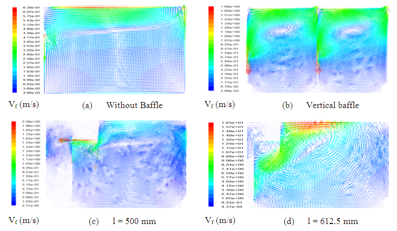 | Figure 6. Velocity field at t=0.1s |
4.3. Magnitude Velocity
- Figure 7 presents the distribution of the magnitude velocity caused by liquid sloshing at t=0.1 s for the different cell designs considered in this study. According to these results, it is clear that the distribution of the magnitude velocity in the cell is affected by the conventional vertical baffle and the mixing element. For the unbaffled cell, the maximum value of the magnitude velocity has been observed on the top of the tank and on the free surface near the left wall. For the cell with mixing element with l=612.5 mm, the highest value of the magnitude velocity is located between the free surface and the side up wall near the both of right and left side wall. However, for the baffled cell with conventional baffle, the highest value of magnitude velocity is located at the free surface close to the left wall and the baffle on the right. The maximum magnitude velocity value has been observed in the baffled cell with mixing element equal to l=612.5 mm. It is located near the baffle and the up side wall. However, the minimum value has been observed for the unbaffled cell. Therefore, it appears that the distribution of the magnitude velocity for the cell with the vertical baffle is different to the case of the unbaffled cell. Also, the mixing element considerably affects the distribution of the magnitude velocity in the cell.
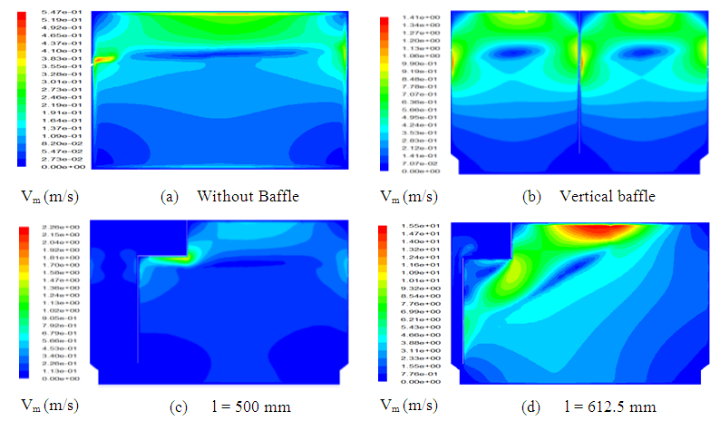 | Figure 7. Distribution of the velocity magnitude at t=0.1s |
4.4. Vorticity
- The distribution of the vorticity caused by the motion of the liquid in the cell at different probes and corresponding to the different design of the cell is shown in figure 8. According to these results, it appears that the use of the conventional vertical baffle changes the behavior of the vorticity in the cell. Also, the distribution of the vorticity for the cell with mixing element is different to the unbaffled cell and the baffled cell with the conventional baffle. The maximum value of vorticity is reached for the cell with mixing element equal to l=612.5 mm. This maximum value is located at the corner of the horizontal and the vertical baffle. However, the minimum value has been observed for the case of the unbaffled cell. For the battery cell without baffle, the highest value of vorticity is located at the free surface and close to the left wall. For the battery cell with l=400 mm, the highest value of vorticity value is located at the free surface and close to the left wall and the baffle on the right. However, for the two cases with mixing element with l=500 mm and l=612.5 mm, the maximum value is located at the corner of the horizontal and vertical baffle.
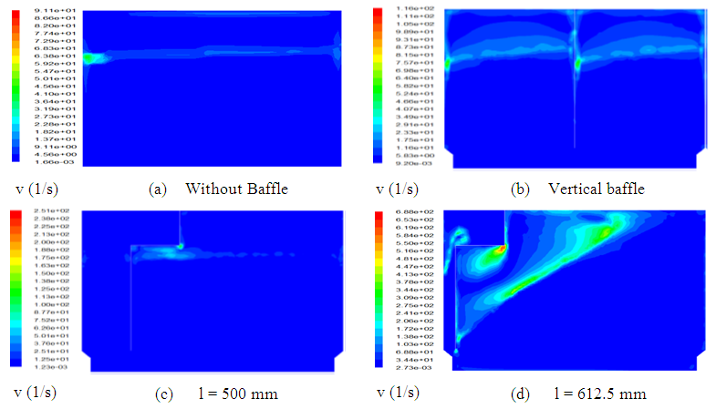 | Figure 8. Vorticity at t=0.1s |
4.5. Turbulent Kinetic Energy
- The distribution of the turbulent kinetic energy caused by liquid sloshing at different probes for the design of the battery cell is shown in figure 9. According to these results, it has been observed that the turbulent kinetic energy is maximum for the battery cell without baffle and it is minimum for the baffled cell with mixing element equal to l= 500 mm. The wake characteristic of the maximum values of the turbulent kinetic energy appears on the whole volume of water. However, the wake characteristic of the minimum values appears on the areas close to the wall and the baffle. For the three designs with baffle, the maximum value of the turbulent kinetic energy has been observed for the cell with mixing element for the case of l=612.5 mm.
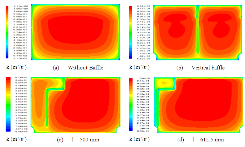 | Figure 9. Distribution of Turbulent kinetic energy at t = 0.1 s |
4.6. Dissipation Rate of the Turbulent Kinetic Energy
- The distribution of the dissipation rate of the turbulent kinetic energy in the cell is shown in figure 10 for different cases considered in this study. According to these results, the dissipation rate of the turbulent kinetic energy is maximal for the cell with mixing element characterized by l=612.5 mm and it is minimal for the unbaffled cell. The wake characteristic of the maximum values of the dissipation rate of the turbulent kinetic energy appears near the walls for the unbaffled cell and under the baffle near the walls for the others cases. Therefore, it is clear that the mixing element affects considerably the dissipation rate of the turbulent kinetic energy.
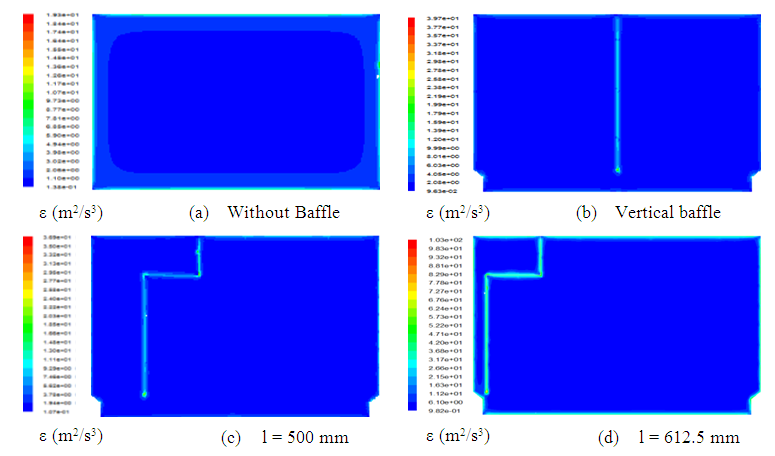 | Figure 10. Distribution of the turbulent dissipation rate of the turbulent kinetic energy at t = 0.1s |
5. Comparison with Experimental Results
- Figure 11 shows the variation of the static pressure for the different designs of the battery cell. Particularly, we have focused on the behaviors at the point defined by x=0.001 m, y=0.5 m and z=0.2 m. For the unbaffled battery cell, it has been noted that the static pressure varies periodically with time. These numerical results are expected since the cell is subject to a periodic sinusoidal motion. For the different design of the baffled cell, the variation of the static pressure over time is no longer sinusoidal under the baffle effect. The maximum value has been observed for the cell with mixing element for the case of l=500 mm at t=15 s. Indeed, we have compared our numerical results for the case of the unbaffled cell with the experimental results of Kang and Lee [14] and the numerical results of Chen et al. [15]. A good agreement was shown which confirms the validity of our numerical model.
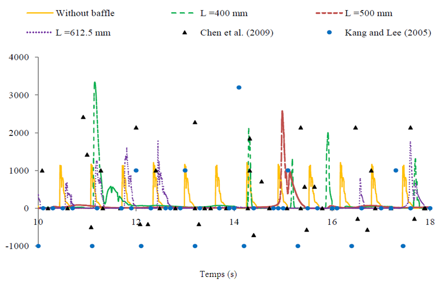 | Figure 11. Pressure profile |
6. Conclusions
- In this work, we have studied the mixing element effect on the hydrodynamic structure of the battery cell. The cell is subjected to an external sinusoidal excitation. The VoF method is used to predict the free surface evolution. The governing equations are solved numerically using the software ‘Fluent’ to determine and describe the local characteristics of the flow fields. The numerical results are presented for the unbaffled cell, cell with vertical baffle in the center and the cell with two designs of mixing element. It appears that the hydrodynamic structure of battery is considerably affected by the vertical baffle and the mixing element. The use of the mixing element creates a recirculation zones on the whole volume of the liquid and the value of velocity is more important. For the vorticity, the turbulent kinetic energy and the dissipation rate of the turbulent kinetic energy, the maximum value has been observed in the case of the cell with mixing element.In the future, we propose to develop an experimental setup to study the sloshing phenomena for other representative cases.
ACKNOWLEDGEMENTS
- The research is conducted in an MOBIDOC thesis funded by the European Union (EU) under the program PASRI (Projet d’Appui au Système de Recherche et de l’Innovation).