Jayann Ismar Lira Almeida1, Marcelo Cavalcanti Rodrigues2
1Department of Mechanical Engineering, Federal University of Bahia, Bahia, Brazil
2Department of Mechanical Engineering, Federal University of Paraíba, Paraíba, Brazil
Correspondence to: Jayann Ismar Lira Almeida, Department of Mechanical Engineering, Federal University of Bahia, Bahia, Brazil.
| Email: |  |
Copyright © 2016 Scientific & Academic Publishing. All Rights Reserved.
This work is licensed under the Creative Commons Attribution International License (CC BY).
http://creativecommons.org/licenses/by/4.0/

Abstract
This study presents a modeling and the structural integrity of two types of repairs in cylindrical pressure vessels (retraction and Welding) using the Fitness-for-service. Fitness-for-service (FFS) is a quantitative technical evaluation of operational components in the context of pressure vessels and piping systems, FFS assessment is performed periodically to ensure operational safety and structural integrity. In retraction pressure vessel repairs, it creates a cylinder of thick walls rolled through the contraction of an outer cylinder to increase the working pressure of the pressure vessel and sleeve. With the welding repair, the sleeve is attached to the pressure vessel through two longitudinal and two transversal welds. The objective is to analyze the von Mises stresses with corroded pressure vessel and compare the results the permissible stress of the material with this model the two types of repairs and checking the tensions reductions using numerical analysis via Finite Element. This work shows that the union of numerical analysis with the Fitness-for-service can be used efficiently and objectivity in similar situations like these that is not analytical solutions for these cases.
Keywords:
Structural Integrity, Pressure Vessel, Repairs, Finite Elements
Cite this paper: Jayann Ismar Lira Almeida, Marcelo Cavalcanti Rodrigues, Modeling and Structural Numerical Analysis of a Cylindrical Pressure Vessel Using the Standard ASME PCC-2-2008, International Journal of Mechanics and Applications, Vol. 6 No. 2, 2016, pp. 17-24. doi: 10.5923/j.mechanics.20160602.01.
1. Introduction
Structural integrity is of considerable importance in order to avoid failures of mechanical components and structures in a number of industrial sectors. They are considered to be an important tool for ensuring the safety and economy of an operating plant. Fitness for Service (FFS) assessment is widely used as a tool to demonstrate the structural integrity of ageing pressure components containing damage. The ability to demonstrate the structural integrity of an in service component that sustained some damage or contains a flaw is termed as integrity assessment or fitness for service and is extensively dealt with by assessment procedures such as R6 [1]. Pressure vessels are devices used in process industries, oil refineries, petrochemical, food and pharmaceutical industries. Telles [2] says that this equipment must be designed and constructed to avoid of the damages causes that are: excessive elastic deformation, including elastic instability, excessive plastic deformation, including plastic instability, high local stresses, and high temperature creep, brittle fracture at low temperature, fatigue and corrosion.A number of FFS assessment procedures are available in practice e.g., API 579 [3], R5 [4] and R6 procedures, and SINTAP [5] which has been superseded by FITNET [6]. An overview of the SINTAP procedure has been given by Ainsworth et al. [7]. These procedures are mostly semi-empirical and are based on extensive experimental data. The most widely used criteria for assessment of corroded pipes are called "effective area methods." The methods include ASME B31G [8], Modified B31G and PRC RSTRENG [9]. The standard procedures for fitness for service evaluations in the oil and gas sector for pressurized components are from API 579, whose assessment procedures are in turn based on the ASME B31G and the RSTRENG criteria. In practice, fitness for service evaluations are conducted periodically in order to determine the acceptability of in-service components and structures for continued service. Extended evaluations are often carried out in an effort to schedule routine inspection and estimate the remaining life of the component.Dong [10] developed a model using the technique element birth to simulate the metal deposition, which is valid in cases where there is no need for thermal analysis as there is no sudden temperature variations. This model is a combination of a 2D model with a small permissible variation in results over the thickness. This concept eliminates the effect of heat transfer through the thickness of the plate, which is to great effect in the case of welding thick plates.Hibbit and Marcal, [11] conducted an advanced modeling procedure for a full 3D simulation of the welding process. The loading of the welded structure, due to operating conditions, temperature dependent material properties and phase transformation were recorded in your model.Friedman [12] developed a comprehensive two-dimensional analysis by noting that the temperature profile does not vary with time, but moves at constant speed along the weld line, the study site was reduced to evaluate the temperature profile a section perpendicular to the welding line. Sims et al. [13] have studied the effect of thinned areas in pressure vessels and storage tanks in an effort to assess the remaining strength of the damaged structure. An empirical equation has been developed by curve fitting the inelastic finite element analysis (FEA) results. They have compared the results with ASME B31G criteria, which is commonly used for determining the remaining strength of corroded pipelines. The results are in reasonably good agreement with ASME B31G, especially for shells having a relatively smaller diameter-to-thickness ratio.In the oil and gas sector, an application that can be given to this type of equipment is in the execution of repairs on pipes using dual channel method Type A and Type B interference. To ensure the radial interference condition between the rails and duct, it is applied a clamping force in the tangential direction of the pipe, with the loading being applied through the concentric streams together on the rails. Studies developed by BORGES, BRAGA, et al., [14] show that the clamping force is one of the main parameters that guarantee the efficiency of this type of repair and should be applied with accuracy and reliability.
2. Theorical Considerations
The equipment analyzed was a pressure vessel made of steel ASTM A516 Grade 70 with longitudinal welded joint with 2.76 MPa (400 psi) of work pressure, 2.03 m (80 in) inside diameter, 0.032 m (1.25 in) of nominal wall thickness and FCA (Future Corrosion Allowance) of the 0.00254 m (0.10 in). The FCA must be established for the intended operating period, this corrosion allowance may be established based upon previous thickness measurements, from corrosion rates on equipment in a similar service, or from information obtained from corrosion design curves. Metal loss on both the inside and outside of a component should be considered when determining a future corrosion allowance. The Figure (1) shows the equipment with grid of inspection by ultrasound tests in the region corroded.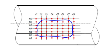 | Figure 1. The grid inspection in the region corroded |
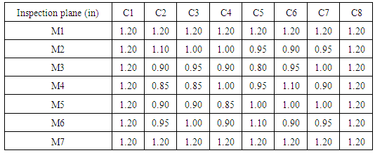
With automatic ultrasound testing aided the wall thicknesses profile of region with metal loss was collected. Each point is a longitudinal distance of 0.0635 m (2.5 in). The inspection grid was created around the region with corrosion (blue line). The Table 1 shows the values for the wall thickness by ultrasound tests in the longitudinal and circunferencial inspection planes.Table 1.
 |
| |
|
For Table 1, the smallest thickness value lies in the M3 row, column C5, which corresponds to a minimum thickness (TMM) 20.32 mm (0.80 in).Pressure vessels subject to corrosion must be repaired to continue with the service for which it is designed when it is not possible to reduce your work pressure through the levels proposed by the Fitness-for-Service. These repairs can be divided into adjustments for retraction and welding.
2.1. Retract Adjustment
In the manufacturing of gun barrels, and various other applications it often creates a cylinder with thick walls laminate by contraction of an outer cylinder (jacket, shell or sleeve) about an inner cylinder (usually called cylinder or tube). The purpose of this manufacturing process is to increase the load capacity of the assembly by the development of an initial state of compressive tangential stresses in the inner cylinder and tangential tensile stresses in the outer cylinder.When the stresses produced by an internal pressure is added to this initial state of stresses, the distribution of stresses resulting makes more efficient use of materials than the distribution that would exist without the initial tensions due to retraction were induced. The determination of stresses in such cylinders laminates requires the solution of a problem using statically indeterminate using deformations equations. The Figure (2) shows a laminated cylinder which was built by heating a sleeve until she could slip on the tube.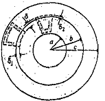 | Figure 2. Adjustment by retraction of a laminate cylinder and pressure vessel |
Heating the sleeve is required for assembly because its internal diameter is slightly smaller than the outer diameter of the pipe. When the sleeve cools, after installation, to develop a contact pressure at the interface, and this pressure produces stresses and deformations in the sleeve and the pressure vessel. The initial difference between the diameters of the pipe and the jacket is known as interference.
2.2. Welding Adjustment
The reinforcements by welding can be designed to cases where there is no pressure or both external and internal pressure. The reinforcements sleeves have proven effective in repairing a wide variety of internal and external defects. Steel sleeves consist of a cylindrical casing placed around the pipe section to be repaired and welded along the two longitudinal seams. There are two types of reinforcements: sleeves of the type A and type B, which can be made in the same type of material or the like.Sleeve Type A: The sleeves type A, their ends are not welded circumferentially, as shown in Fig. (3-a), and thus is not able to contain the internal pressure, but it works as a reinforcement for a defective area. It is only used for the correction of defects that is not leaking and did not expand during service, or when the damage mechanism and growth rate is completely controlled.Sleeve type B: Their ends are welded circumferentially to the pressure vessel, as shown in Fig. (3-b), making it possible to restrain the internal pressure. The sleeves the type B can be used to repair defects leaks or defects which might leak and reducing the axial load capacity of the pipe.The sleeves of the type B should have a thickness equal to or greater than the nominal thickness of the pressure vessel designed for the maximum allowable working pressure and the welding efficiency factor of 0.8, unless the weld is 100% checked by ultrasonic examination, in these cases, the efficiency factor of 1.0 can be applied. If sleeve type B receives axial reinforcements, it must be designed to withstand these loads, and loads of bending acting on the entire glove. The two types of gloves should be at least 100 mm (4 in) long and extend 50 mm (2 in) beyond the default. For the installation of type A and type B reinforcements type A or B, the entire circumference of the pressure vessel in the area to be covered by the sleeve has to be cleaned, so a cleaning the material is required. If the addition of metal to be used is hard, then it should be applied to all slots, wells and depressions. The sleeve must be fitted tightly around the pipe, the mechanical fixing by means of hydraulic, screw, or other devices may be used to secure the adjustment.The weld tip of the pressure vessel should be smooth between the vessel and the weld in order to minimize the stress concentration levels in this region, the angle should not create notches and defects such as undercuts are not allowed. A no spacing adjustment (the gap) is ideal, however, allows up a radial tolerance of up to 2.5 mm (3/32 in.). If the spacing (gap) is excessive, it is necessary technical adjustments to the weld, such as the welded ends and the weld size.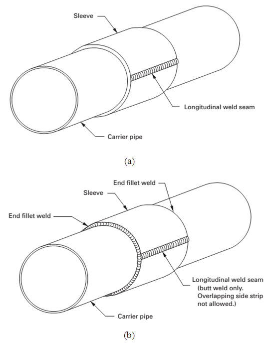 | Figure 3. Scheme of gloves (a) type A and (b) Type B (ASME, 2008) |
2.3. Welding Residual Stress
During the welding process, the heat provided by the power source tends to cause thermal expansion in the heat-affected zones (HAZ). If the component is uniformly heated, will expand uniformly, and no internal stress will be produced. However, since that is very difficult to obtain, a heating no uniformity causes the zones under the effect of lower temperatures to limit the thermal expansion by higher temperatures zones. Then, elastic and plastic deformation (distortions such as warpage) are developed in the welded component, and as a result, internal stresses or residual stresses are developed. These stresses is a thermal mechanical phenomenon that depends by component thermal time history in work operation, thus a transient phenomenon occurs following a subsequent cooling, generating contraction.
2.4. Thermal Considerations
Once the torch produces a temperature gradient within the welded component, the heat transfer by conduction is present. It is modeled by the heat equation, explained below by Eq. (1). | (1) |
Where,  is a density, “c” is a specifi heat, “k” is a thermal conductivity and
  is an internal heat generation. It can still make a simplification, considers the material as isotropic ("K" independent of the direction). [16] says that the most important factor, and that provides more heat to the process, is the electric arc. The heat provided by this thermal power is based on the Joule effect, by Eq. (2):
 | (2) |
Where  is a welding processes efficiency,
  is a welding voltage and
  is a welding current. The heat dissipation of welding zone occurs by three methods: conduction to the inside of the component, convection due flow of the outside air, and radiation to the atmosphere. The convection equation is a Newton Cooling Law, given by Eq. (3):
 | (3) |
Where “h” is a convective coeficiente, “A” is an exposed area,  is a surface temperature, bigger, and
  is a external fluid temperature. The equation that describes the radiationis given by the Stefan-Boltzmann Law, by Eq. (4):
 | (4) |
With  is a emissivity,
  is a Stefan-Boltzmann constant, given by
  , “A” e
  having the same meaning that Newton Cooling Law, and
  representing the neighbor environment temperature.The action of the electric arc is modeled by extending "Moving Heat Flux v.4 by ANSYS." It works on a simplification of the Gaussian temperature distribution model [17], given by Eq. (5):
 | (5) |
In this equation,  defines the instantaneous position Center, point where the heat source is acting in the given time, and that is "v × t" the starting point, with "v", which is welding speed. As "t" varies throughout the analysis, the Center point also varies, always within the joint edge. Furthermore,
  is the heat flow intensity from the action of the arc and
  the incident beam on the component.
2.5. Mechanical Considerations
Performs the transient thermal analysis to get the history of temperatures and is then used as a load for a transient structural analysis to obtaining the residual stresses distribution. Following [18], the deformation increment is then divided into three components. The elastic deformation, from the isotropic Hooke's Law, with Young's modulus dependence on temperature, plastic deformation, measured, in this case, from the bi-linear plastic model and the portion relating to thermal action, obtained due to the thermal expansion coefficient also varies with temperature. Then, in the matrix given by Eq. (6):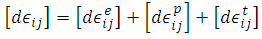 | (6) |
3. Modeling of Cylindrical Pressure Vessel with Repairs
The pressure vessel with external corrosion can be modeled in as follows step by step described below by Almeida, et al. [15]. Figure (4) shows the pressure vessel completely modeled.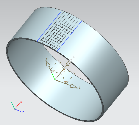 | Figure 4. Pressure vessel modeled with the external corrosion |
3.1. Modeling of Retraction Repair
The parameters for the sleeve model for this type of repair is shown in Fig. (5).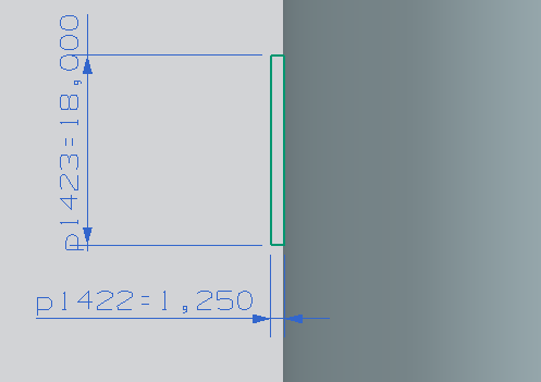 | Figure 5. Parameters for the sleeve model |
The sleeve is designed with a thickness of 1.25 in (31.75 mm), same thickness of the pressure vessel and a length of 18 inches (457.2 mm) long that it covers the entire area of the damage. In Figure (6) has a complete modeling of the sleeve, covering the entire cross-sectional area of the pressure vessel.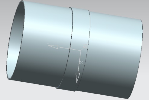 | Figure 6. Full repair modeling of the pressure vessel |
For this type of repair, the length of the sleeve is not restricted, therefore, was adopted it is recommended that the Type B sleeve projects with welds, which is an extension of 50 mm (2 in) beyond the length of the damaged area, which was 14 in (355,6 mm).
3.2. Modeling of Welding Repair
For the modeling of welding repair, some details and care has to be taken into account, is shown below step by step to a complete modeling sleeve with weld.The sleeve is modeled as was done in repair by retraction, with the same parameters, satisfying the requirements for thickness and repair length, as seen in Fig. (6).The first model is made of the weld lengthwise, so as to fix both sides of the sleeve, so that, it is modeled the weld bevel, which in this case is V, as shown in Fig. (7).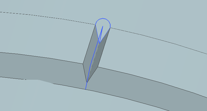 | Figure 7. Chamfer modeling V for longitudinal weld |
After the chamfer, the software contains a weld command, which picks up the chamfer type, then it models the weld bead as follows in Fig. (8).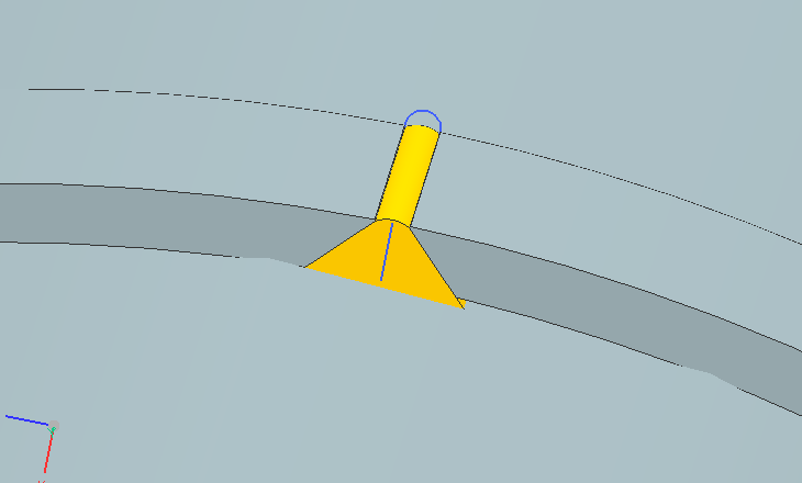 | Figure 8. Modeling of longitudinal weld bead |
Similarly, it is modeling the other longitudinal weld bead located exactly 180° from the first weld bead patterned, as shown in Fig. (9).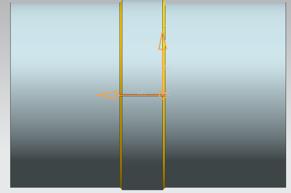 | Figure 9. Detail of the two longitudinal welds forming an angle of 180o |
The next step is to model the two transverse welds which make the junction with the sleeve pressure vessel, this modeling has become a corner joint, as can be seen in Fig. (10).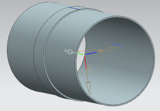 | Figure 10. Detail of the groove between the sleeve and the pressure vessel |
In Figure (11) shows the modeling of weld bead of the transverse regions of the pressure vessel, the angle formed between the repair and the vessel was 45°.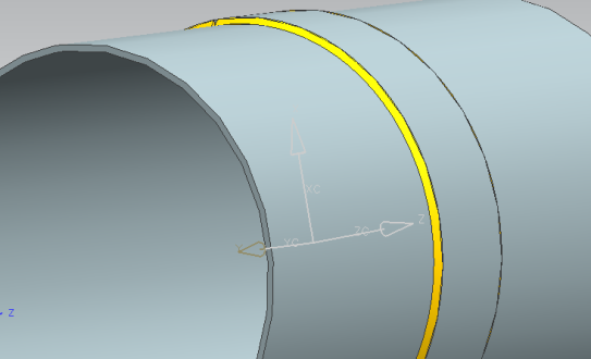 | Figure 11. Modeling of the weld bead of the transverse regions between the sleeve and the pressure vessel at an angle of 45° |
From these modeling, it becomes possible structural numerical analysis of the pressure vessel assembly and repair, the next step is to numerically analyze the structural integrity of those components.
3.3. Model, Mesh and Material
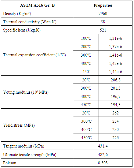
The mechanical properties of steel ASTM A516 G70 Gr are shown in Tab. (2).Table 2. Mechanical properties for steel ASTM A510 Gr 70
 |
| |
|
The plasticity model adopted was the bilinear hardening elastoplastic. The material stress x deformation diagram consists of two linear portions of different slopes, with turning point and corresponding to the material elastic limit.The mesh has 487917 nodes and 229383 tetrahedral elements with 30 millimeters size, and refinement in the weld region. The Fig. (12) shows the mesh detail. | Figure 12. Scheme of detailed mesh elements (a) of pressure vessel and (b) weld |
To take into account the effect of thermal processing of solid-liquid phase was applied to an artificial increase in the specific heat, according to the procedure proposed by [19], by Eq. (7) between the liquidus and solidus points.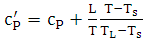 | (7) |
The specific heat  between solid and liquid temperatures was 1437°C and 1501°C respectively, and “L” is the latente heat 205 kJ/kg. These are typical values for low carbon steel found in bibliography.
4. Results and Discussion
It was analysed the structural integrity in two stages, using the repair by retraction, and then repair by weld. The thermal analysis was done and the temperature distribution is showed by Fig. (13). 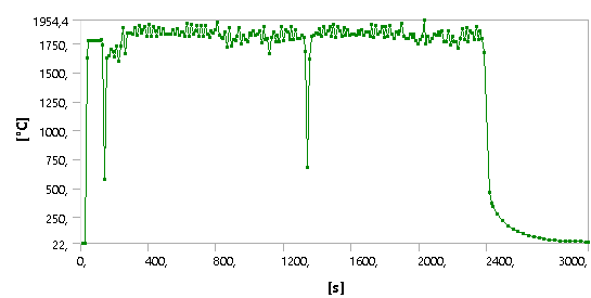 | Figure 13. Temperature distribution during the welding |
Note that there are two temperatures decreases in the ranges of approximately 140 s to 1350 s, this happens in a time interval of a weld bead to another, this time is estimated to 20 s. Furthermore, the weld bead was adopted speed of 6 mm/sec.For longitudinal welds, the estimated time to perform the operation was 93 s, for the circumferential welds the calculated time was 1044 s. The total time of analysis was adopted was 3000 s, the total time includes the time of completion of the welds over a cooling period of the same, producing residual stresses. The following analyses were made at the end time, considering the cooling after welding of application.
4.1. Numerical Structural Analysis Using Repair by Retraction
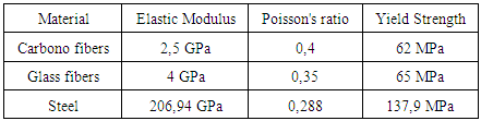
For the numerical analysis using the repair by retraction, it was proposed to select three different materials to the sleeve, they are: glass fibers, carbon fibers and steel. The Table (3) shows the main properties to perform the simulation.Table 3. Mechanical properties of materials required for numerical analysis in the retraction repair
 |
| |
|
It is possible refine only the mesh sleeve or pressure vessel, moreover, it is clear that it was given a cross-section modeling, using only half the vessel set of pressure and repair, this does not interfere in the simulations, as this it was done only to reduce the area of the mesh, and so can refine the results further. After the creation of the mesh, make sure that the boundary conditions, that for this case was formed as follows:● Fixed restriction in all directions in the pressure vessel side and sleeve;● Contact by glue between the outer wall of the pressure vessel and the inner wall of the sleeve;● Application of the internal pressure of 2.76 MPa (400 psi).This makes it possible to simulate and analyze the stress distribution for the three situations proposals. The Figure (14) shows the results of the stress distribution to the three materials.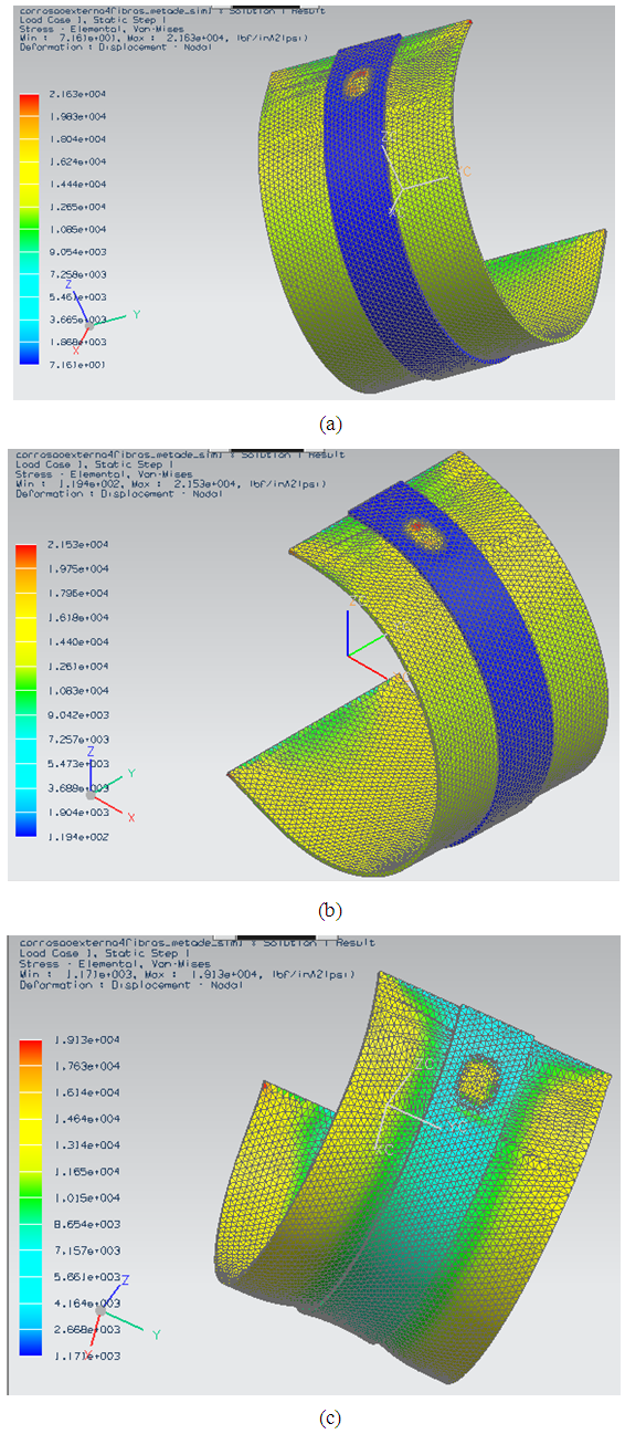 | Figure 14. Stress distribution for the materials with repairs of (a) carbon fiber, (b) glass fiber and (c) steel |
The maximum von Mises stress found for the repair of carbon fiber, as seen in Fig. (14-a) was 149.13 MPa (kpsi 21.63), therefore, the vessel still operates at risk, since their allowable stress is 137.70 MPa (19.9 kpsi). A similar situation occurs with the glass fiber in accordance with Fig. (14-b), the maximum von Mises Stress was found 148.44 MPa (kpsi 21,53). Finally, with ordinary steel repair, the maximum stress distribution was found to be 139.9 MPa (19.13 kpsi), as shown in Fig. (14-c). The last repair, therefore, puts the pressure vessel to operate safely in that the maximum tension found was below the allowable stress of the tube material.
4.2. Numerical Structural Analysis Using Repair Welding
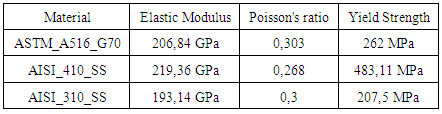
When performing the simulations with repair welding, it is determined first the three materials to be used in the three regions of modeling, they are: the pressure vessel, the sleeve for repair and the weld bead.It was then the following materials: Standard material from the pressure vessel: ASTM A516 G70, the sleeve repair: AISI_410_SS and the weld bead: AISI_310_SS. The Table (4) shows the mechanical properties of these materials necessary for the simulations.Table 4. Mechanical properties of materials required for numerical analysis in the welding repair
 |
| |
|
The Figure (15) shows the stress distribution result for the adjustment by welding.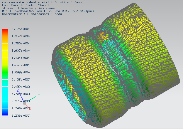 | Figure 15. Von Mises stress distribution for the set of pressure and vessel repair by welding |
It is noticed that there is the formation of a "neck" in the repair area, a fact that is logical with reality, because with the expansion of the inner wall due to pressure, the pipe region that is under the glove is restricted, preventing expansion.It is observed that the maximum von Mises stress was 146.51 MPa (21.25 kpsi), thereby the pressure vessel will continue to operate at risk because the stress is found greater than the allowable stress of the pressure vessel.
5. Conclusions
This paper aims to analyze the structural integrity of a cylindrical pressure vessel subject to corrosion and with the repair methods of the standard ASME PCC-2-2008 through numerical solution, the first step was to make an acceptable modeling of both types of repairs proposed.In the repair by retraction, the carbon fibers and glass fibers materials requires increased thickness of the sleeve, since the stress is found higher than the allowable stress of the material, then you must increase the thickness and then redo analysis. Only for steel, the equipment with the repair can again operate safely, the thickness proposal in this case hs followed the expectations.In the repair by welding, separated into three materials the vessel assembly and pressure sleeve, the choice of separate the materials into three is due the results to converge to the real case. The results showed that for the proposed thickness, the vessel will operate in the risk zone. A successful numerical analysis can show the best option for the structural analysis of equipment in general (in this case, the pressure vessel) due to objectivity and speed with which results can approach the reality, because in this case with the models already proposed, simply put the data of the materials, as well as the correctly boundary conditions, and thus has the solutions.
ACKNOWLEDGEMENTS
This work was supported by the CAPES, CNPQ, Federal University of Paraiba, Department of Mechanical Engineering and Integrity and Inspection Laboratory.
References
| [1] | R6. Assessing the integrity of structures containing defects. British Energy, Gloucester, UK, 1995. |
| [2] | Telles, P. C. da Silva, Vasos de Pressão, 2ª edição, Ed. LTC – Livros Técnico e Científicos Editora S.A, Rio de Janeiro, Brasil, 1996. |
| [3] | API Recommended Practice 579, Fitness for service, API Publishing Service (American Petroleum Institute), first edition, Washington D.C., Jan. 2000. |
| [4] | R5. Assessment procedure for the high temperature response of structures. British Energy 2003; 3. |
| [5] | Sintap. Structural integrity assessment procedure for European industry. Project BE95-1426, Final Procedure, British Steel Report, Rotherham; 1999. |
| [6] | Fitnet. Fitness-for-service procedure. Final Technical Report. Geesthacht: GKSS Research Centre; 2006. |
| [7] | Ainsworth R.A., Bannister A.C., Zerbst U., An overview of the European flaw assessment procedure SINTAP and its validation. Int J Pressure Vessels Piping 2000;77:869 e 76. |
| [8] | ASME. Manual for determining the remaining strength of corroded pipelines. American National Standards Institute (ANSI)/ American Society of Mechanical Engineers (ASME) B31G. 1984. |
| [9] | Kiefner J.F., Vieth P.H. A modified criterion for evaluating the remaining strength of corroded pipe (with RSTRENG). American Gas Assoc, Catalogue L51609, PR3-805. December 1989. |
| [10] | Dong, P., 2001, ‘‘Residual Stress Analyses Multi-Pass Birth Weld: 3-D Special Shell versus Axisymmetric Models’’. ASME J. Pressure Vessel Technol., 123, May, pp. 207–213;. |
| [11] | Hibbit, H.D., Marcal, P.V., 1973, ‘‘A Numerical, ThermoMechanical Model for the Welding and Subsequent Loading of a Fabricated Structure’’. Comput. Struct., 3, pp. 1145–1174. |
| [12] | Friedman, E., 1975: Journal Pressure Vessel and Technology, Trans. ASME, vol 97, pp. 206-13. |
| [13] | Sims J.R., Hantz B.F., Kuehn K.E., A basis for the fitness for servisse evaluation of thin areas in pressure vessels and storage tanks. Pressure vessel fracture, fatigue and life management. ASME PVP 1992;233:51–8. |
| [14] | Borges, M.F., Braga, S.S., et al., 2013 “Finite Element Analysis of Repair Technique on In-Service Pipeline with Dent”. IBP 1325_13, Rio Pipeline Conference & Exposition;. |
| [15] | Almeida, J.I.L., 2012, “Análise Numérica da Integridade Estrutural de Vasos de Pressão com Corrosão Usando a Norma API 579”, Master Thesis. |
| [16] | Masubachi, Koichi. Analysis of Welded Structures: Residual Stresses, Distortion and their Consequences. 1 ed. Massachusetts: Pergamon Press, 1980. 642 p. |
| [17] | Goldak, J.; Chakravarti, A.; Bibby, M., A new finite element model for welding heat sources, Metallurgical Transactions B, v. 15B, pp. 299-305, 1984. |
| [18] | Chang, K-Ho, Lee, C, Park, K. T., You Y.J., Joo, B.C., and Jang G.C., (2010). Analysis of Residual Stress in Stainless Steel Pipe Weld Subject to Mechanical Axial Tension Loading. International Journal of Steel Structures, no 4, pp. 411-418. |
| [19] | Liu, W.; Ma, J.; Kong, F.; Liu, S.; Kovacevic, R.; Numerical Modeling and Experimental Verification of Residual Stress in Autogenous Laser Welding of High-Strength Steel, Lasers Manuf. Mater. Process., v. 2, pp. 24-42, 2015. |

 Abstract
 Reference
 Full-Text PDF
 Full-text HTML